Yam, Kit L. (ed.). The Wiley encyclopedia of packaging technology
Подождите немного. Документ загружается.

cracking, failure on drop test, and even pinholing;
thick sections can act as heatsinks after the bottle is
molded, and the uneven cooling and shrinkage can
lead to bottle distortion. In the case of product that
will cool or outgas after the container is sealed, there
is a potential for distortion due to negative or
positive pressure. This can require special molded-
in structures, expansion areas, or controlled wall
thickness to minimize these effects. The preciseness
of wall thickness guidelines should be determined by
how critical it is for performance of the bottle.
4. Bottle Stability Is Critical. This is especially true for
many of the tall, thin (depth) bottles frequently used
in consumer products to maximize shelf impression.
In injection blow molding, the height of the pushup
(the center of the base of the bottle) can be adjusted.
The center of the bottle base must be high enough to
not ‘‘belly out’’ for a full or empty bottle, or the
bottom of the bottle will be a round surface. Various
aids to stability include molding bottom rings (ra-
diused or with a flat land area) or feet (three or four).
It is a good idea to put a slight depression in the
vicinity of the parting line so that a slightly raised
parting line will not contribute to instability. The
best solution depends on the bottle’s general shape
and center of gravity and on the controls available in
the molding process.
5. Embossed or Debossed Decorations. These include
logos, which can be a free or inexpensive way to add
information to the bottle. However, care should be
taken to avoid thin spots, undercuts, or sharp edges.
6. Information that Is Frequently Molded into the
Bottom of the Bottle. This includes material identi-
fication symbol (recycling logo, legally required to be
on the bottle in several states), mold and cavity
number (for quality checks and troubleshooting),
and a molder or company logo. Placement should
be planned ahead of time, especially because this
may affect bottle stability. These should generally
not touch or cross the parting line.
7. The Bottle Sealing Area Should Be Closely Specified.
For standard continuous thread closures, lined or
unlined, the land seal area at the top of the con-
tainer is critical. It needs to be flat, horizontal, and
free of dips or nicks. If the flat surface is going to be
angled, care should be taken to specify a continuous
surface that will create a seal. A minimum land
width (flat neck thickness at the top) can be speci-
fied. If a valve seal closure is to be used, the
circumference inside the finish where it meets the
valve is critical.
8. Anticipate Pressure Differentials. Special product,
filling, and distribution circumstances can lead to
pressure differentials between the inside and out-
side of the filled and sealed container over the course
of product life. Examples of this include hot fill,
product outgassing, product migration through
walls causing suckback, and changes in external
pressure and temperature during distribution, sto-
rage, and handling. Flexible panels or more flexible
materials will not prevent dimensional change, but
can prevent damage to the container and allow it
to be aesthetically acceptable. Variations in wall
thickness support ribs, and stiffer materials can
strengthen containers against dimensional changes
to some extent. Depending on the product, one- or
two-way valves can be added to the closure or inner
seal.
9. Labeling and Decoration. These are a major con-
sideration in bottle design. A label panel must be flat
or have a surface that curves in only one direction.
Many label areas are recessed or provide top and
bottom ‘‘bumpers’’ to protect the label against scuff-
ing during normal handling and distribution. The
maximum label area is determined by a combination
of the tolerances of the label placement equipment,
the label dimensions, and the usable label panel
dimensions. The additive tolerances need to be sub-
tracted from the specified label panel size. Major
labeling or decoration methods include the follow-
ing: (a) In-line labeling (filling line)—labels (gener-
ally pressure-sensitive or plain-paper and glue) are
applied on the filling line; (b) postmold labeling—
labels (generally pressure-sensitive or heat-trans-
fer) are applied soon after the bottle is molded
(further shrinkage in the bottle, particularly over
the next 24 hours, must be taken into account); (c)
in-mold labeling—labels (either plastic or paper) are
applied inside the mold during the molding process
(bottle versus label shrinkage must be designed into
the bottle tooling, especially for paper labels); and
(d) direct application to bottle—instead of applying a
label, the container is decorated by printing or silk
screening directly onto the bottle.
HDPE or PP bottles usually require flame treatment prior
to decoration or labeling. Round bottles may need a
rotational guide in the bottom to help control them during
either process. (See also Labels and labeling machinery.)
Industry Standards
As
in any purchased
item, specifications and tolerances
should be set up between the customer and the supplier.
However, the designer is greatly aided by industry stan-
dards. Currently, ASTM publishes D2911-94(2005) Stan-
dard Specification for Dimensions and Tolerances for
Plastic Bottles with standard screw closure neck finish
dimensions, threads, and tolerances, and tolerances for
various ranges of bottle capacity (up to 5 gallons) and body
dimensions. These standards are modified on an ongoing
basis and should regularly be checked for updates. In
addition to dimensional standards, there are procedures
for stress crack resistance, crush strength, drop impact
and additional tests (3). The existence of standard finishes
greatly facilitates the interchangeability of various stock
and custom closures that might be available. The standard
tolerances also provide a good starting point for specifica-
tions. The designer might wish to tighten some of these
tolerances as required, but should be prepared to work
158 BOTTLE DESIGN, PLASTIC

closely with any vendors ahead of time to ensure manu-
facturing capability.
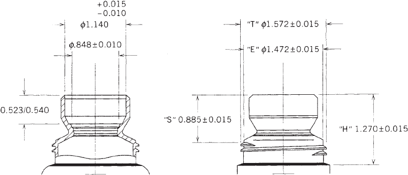
A typical dimensioned bottle is shown in Figure 2.
Table 1 describes a typical container’s dimensions and
their importance. The sample given is a standard contin-
uous thread finish container, which uses a standard
screw-on/screw-off closure that is common on many con-
sumer bottles.
Materials and Colorants
Critical criteria for selection of bottle materials include
the following:
1. Cost and availability—should be calculated by the
bottle, not just the pound.
2. Environmental—recyclability and availability of
recycled material, toxicity or biodegradability.
3. Clarity or opacity.
4. Stiffness or squeezability.
5. Water or moisture vapor transmission rate (WVTR
or MVTR).
6. Gas permeability.
7. Chemical resistance to type of chemicals required.
8. Temperature range.
9. Impact strength.
10. Environmental stress—crack resistance (ESCR)
Materials generally used for bottles in the United States
include high-density polyethylene (HDPE), polypropylene
(PP), low-density polyethylene (LDPE), linear low-density
polyethylene (LLDPE), polyvinyl chloride (PVC), poly-
ethylene terephthalate (PET), and polystyrene (PS). Of
these, HDPE and PET make up the great majority of
Figure 2. Typical dimensions of a
plastic bottle. Bottle and finish no-
menclature. T, diameter of thread;
E, diameter of root of thread; I,
diameter of inside; S, distance of
thread start to top of finish; and H,
height of finish.
Table 1. Bottle Dimensions
Dimension Description Purpose
T Thread outer diameter Cap fit and torque control.
E Diameter between threads Cap fit and torque control.
H Height from shoulder to top of finish Bottom of closure must clear shoulder at maximum torque
for proper sealing. The maximum minus minimum H
(DH) should also be specified to limit neck ‘‘cocking,’’
which will also adversely affect the seal.
S Height from top of thread to top of finish Thread engagement.
I Inside diameter of finish Minimum is for filling tube clearance only. Custom detail
should be added for placement of special fitments.
Ovality T
max
T
min
or other area Ovality in the finish can affect closure fit, torque control, or
fitment integrity and fit. Specification should be based on
requirements and manufacturing capabilities.
Land width Sealing width on top of finish Cap seal and torque control. Specification should be based
on requirements and manufacturing capabilities.
Overflow capacity Volumetric capacity of bottle to top Consistent filling of bottle with proper amount of product
and correct aesthetic fill height.
Overall dimensions Height, width, and depth at maximum point Proper machinability on filling line and fit in secondary
packaging. Additional dimensions are specified in article
drawing.
Weight Weight of empty bottle Cost control, to ensure sufficient material, and fill weight
control.
Wall thickness Thickness of wall at minimum and specified points Thin spots can lead to drop failure or stress crack. Wall
thickness should be specified at the absolute minimum
found on the bottle (this can vary as to location) and at
other critical locations if necessary.
BOTTLE DESIGN, PLASTIC 159
containers by number and weight. Other materials, in-
cluding engineering plastics such as polycarbonate, are
used for special applications. Individual material proper-
ties can be found in detail under their separate articles.
Many materials can have their properties significantly
modified by additives such as plasticizers, fillers, impact
modifiers, antistatic agents, and UV (ultraviolet radiation)
inhibitors. Copolymers and multilayer coextrusions can
further enhance a material.
Colorants are added to provide color and/or opacity to
the material. Pigments, an opacity agent (such as tita-
nium dioxide), and a compatible base material are com-
pounded and added to the regular plastic during the
molding process. The colorant loading, wall thickness of
the plastic, and color and opacity of the product all affect
the final aesthetics of the filled bottle (see Colorants,
plastic).
Different materials and to some extent different color-
ants all affect the shrinkage and final performance of a
bottle. This must be taken into consideration for testing
and qualification.
Computer Utilization in the Design Process
The computer is an integral part of the bottle design
process, and new ways of using it are being added con-
tinuously. Uses include:
Specifications. Bottle specifications are computerized
at both the customer and supplier level.
Computer-Aided Design/Manufacturing (CAD/CAM).
Bottle drawings are performed on CAD systems, with
improved opportunity for analysis and exploration of
options and variables. Mold makers frequently use a
CAM system for production of the mold. Some forms
of rapid prototyping can also be performed.
Analysis and Data Recording. Test data can be both
directly recorded and analyzed on the computer.
Sophisticated engineering programs, such as finite-
element analysis, can be used to compute and visua-
lize stresses at various points.
Pallet Loads. Several programs, such as those pro-
duced by CAPE (4) or TOPS (5), allow quick calcula-
tions of finished pallet options based on bottle sizes.
This allows for pallet load optimization at the initial
design stage.
In addition, there is various software to do everything
from evaluating heat transfer in mold design to visualiz-
ing product placement on the supermarket shelf.
PROTOTYPING AND TESTING
Once the bottle is designed and unit-cavity samples have
been produced in the proper materials, a testing program
must be initiated. A testing protocol should be established
that checks bottles against both their specifications and
the requirement list that was generated.
SPECIALTY BOTTLE REQUIREMENTS
A number of specialty bottles have distinctive require-
ments. Some of these include:
Roll-On. A round ball is inserted in the finish; rolling
the ball against a surface (clothes, parts of the
body) dispenses a liquid. The ball is held in place
between two rings in the finish. The most common
method of sealing is to torque the cap so that it
pushes the ball down tightly against the lower ring
(Figure 3).
Plug. A small orifice plug is placed into the finish so
that product dispensing can be controlled (eye or
nose drops, creams). The plug must be inserted
without crushing the bottle body or neck finish and
yet be difficult to remove. Controlled dimensions or
retention rings are some of the solutions.
Drain-Back Closures. These fitments provide pour
spouts and matching caps for detergents and fabric
softeners. The drain-back section is sometimes
Figure 3. Typical special rollon finish.
160 BOTTLE DESIGN, PLASTIC
placed inside the finish similar to a plug, but fre-
quently before filling.
Child-Resistant Closure (CRC). There are a number
of different types of these closures on the market,
generally requiring special finishes. The popular
‘‘push and turn’’ instruction requires sufficient H
dimension to allow the cap to be pushed down for
thread engagement. The ‘‘line up the arrows’’ in-
struction requires a ring with an interruption under
the arrow. Protocol testing includes both closures
and containers (see Child-resistant packaging).
Nonremovable Closure. Some dispensing closures are
designed to prevent removal. One design has ratch-
ets that can easily be overridden for tightening but
prevent loosening (see Closures, bottle and jar).
Tamper Band. Many products (drugs and foods) have
tamper bands to show tamper evidence. The band
must be able to anchor itself to something on the
bottle—a ring is sometimes added to the outside
under the finish area (see Bands, shrink; Tamper-
evident packaging).
ENVIRONMENTAL CONCERNS
Whether driven by legislation, consumer preference, or
the desire to be a good corporate citizen, today’s packager
has to take environmental concerns into account when
producing a package. A new plastic bottle presents a
special challenge and opportunity. The following is a brief
look at plastic bottles and the ways of handling solid waste
other than the landfill:
1. Reduce. The preferred way of handling the pro-
blem—creating less waste in the first place—has
another major advantage. The less plastic we use,
the more money we save. This can be accomplished
through optimizing structural design, eliminating
oversizing, and taking advantage of the best materi-
als for the job.
2. Reuse. Although returnable bottles may seem like
an obvious answer, this is not necessarily the case:
‘‘to withstand the process of return and refill, a
refillable container must be about twice as heavy
as a one-way container of the same material.’’ This
adds impact to energy usage and eventual disposal
also (6). However, a number of consumer products,
notably detergents and cleaning products, are sold
in bottles that the consumer refills without having to
undergo this process. The refill packages are de-
signed with less plastic and frills, or are made of
lighterweight or more easily crushable materials.
3. Recycle (Recyclable). Everything can be recycled by
somebody, somehow, somewhere. However, unless a
substantial percentage of the bottles can realisti-
cally be recycled in the near future, this doesn’t
mean too much. Although the percentages of bottles
that are recycled or could be from programs in
place changes constantly, the bulk of recycling is
with PET (mostly soda bottles, although some areas
have added capabilities to accept other bottles) or
HDPE (mostly homopolymer milk bottles, although
some areas now accept other containers including
copolymer detergent bottles). Plastic containers can
be recycled into plastic lumber, piping, or even
carpet liner as well as packaging containers. The
recycling rate for plastic containers has been esti-
mated at 24.3% for 2005, based on pounds of resin
sold (7). To aid in potential recycling, as well as
comply with the law in most states, a material
identification logo, such as the SPI resin identifica-
tion code, (8) should be added to all containers.
4. Recycle (Recycled). The relatively high cost of col-
lecting, sorting, cleaning, and processing good-qual-
ity post-consumer HDPE generally makes it more
expensive pound for pound than virgin resin. As the
process becomes more efficient and if the cost of
virgin continues to climb, this may change. Because
of the unpredictability of the color and properties of
much regrind, it is frequently used as a middle layer
in a multilayer coextruded bottle or as a small
percentage in a dark bottle holding nonaggressive
product. Food and drug primary packages may not
be permitted to use reground plastic directly,
although repolymerization or special considerations
can be investigated.
5. Incineration and Conversion to Energy. Plastics
produce heat when burned, which, in turn, can be
converted to other forms of energy. The presence of
heavy metals (such as lead or cadmium used in some
colorants) in a bottle will leave toxic waste residue.
Several states have outlawed the use of these mate-
rials, and it is critical to avoid them. Older incin-
erators may also have a problem with chloride
containing materials such as PVC (9).
BIBLIOGRAPHY
1. R. J. Kelsey, Packaging in Today’s Society, St. Regis Paper
Company, 1978, p. 69.
2. S. Levy and J. H. DuBois, Plastic Product Design Engineering
Handbook, Van Nostrand Reinhold, New York, 1977, pp. 169–
170.
3. ASTM International Web information. Available at http://
www.astm.org/cgi-bin/SoftCart.exe/COMMIT/SUBCOMMIT/
D2020.htm?L+mystore+vvra4003+1173846722. Accessed May
30, 2007.
4. CAPE Systems, Inc. Web information. Available at http://
capesystems.com. Accessed May 30, 2007.
5. TOPS Engineering Corporation, Web information. Available at
http://www.topseng.com/. Accessed May 30, 2007.
6. L. Erwin and L. H. Healy, Jr., Packaging and Solid Waste
Management Strategies, American Management Association,
New York, 1990, p. 26.
7. Plastics Division of the American Chemistry Council and the
Association of Postconsumer Plastic Recyclers 2005 National
Post-Consumer Plastics Bottle Recycling Report Web informa-
tion. Available at http://www.plasticsrecycling.org/documents/
2005NationalPost-ConsumerPlasticsBottleRecyclingReportFI-
NAL.pdf. Accessed May 30, 2007.
BOTTLE DESIGN, PLASTIC 161
8. The Society of the Plastics Industry—SPI Resin Identification
Code Guide To Correct Use Web information. Available at
http://www.plasticsindustry.org/outreach/recycling/2124.htm.
Accessed May 30, 2007.
9. L. Erwin and L. H. Healy, Jr., Packaging and Solid Waste
Management Strategies, American Management Association,
New York, 1990, p. 37.
General References
R. J. Kelsey, Packaging in Today’s Society, St. Regis Paper
Company, 1978.
S. Levy and J. H. DuBois, Plastic Product Design Engineering
Handbook, Van Nostrand Reinhold, New York, 1977.
The Society of the Plastics Industry—Web site: http://www.plas-
ticsindustry.org/.
ASTM International—Web site: http://www.astm.org/.
The Association of Postconsumer Plastic Recyclers—Web site:
http://www.plasticsrecycling.org.
L. Erwin and L. H. Healy, Jr., Packaging and Solid Waste
Management Strategies, American Management Association,
New York, 1990.
S. Selke, Ph.D., Packaging and the Environment, Technomic
Publishing Inc., Lancaster, PA, 1990.
J. Hanlon, Handbook of Package Engineering, second edition,
Technomic Publishing Co., Lancaster, PA, 1992.
A. Mandel, ‘‘Bottle Design, Plastic’’ in The Wiley Encyclopedia of
Packaging Technology, 2nd edition, John Wiley & Sons, New
York, 1997, p.93.
A. Mandel, ‘‘Packaging Beer in Plastic Bottles,’’ Teltech online
article, May 1999.
BOXES, CORRUGATED
GENE A. FOSTER
Middlesex Container Company,
Inc., Milltown, New Jersey
Updated by Staff
INTRODUCTION
Corrugated containers (erroneously termed cardboard
boxes) became the shipping package of preference in the
early 1900s as a replacement for wooden crates. Corru-
gated fiberboard packaging is, in terms of tonnage, by far
the most common type of paper and paperboard-based
packaging (1).
The corrugated shipping container and related inner
packaging is multifunctional. Its varied uses include
wrapping, enclosing, protecting, cushioning, indexing,
stacking, and displaying. The basic function of the packa-
ging is to protect the product during distribution until the
product is removed from the package. The growing use of
palletization in warehousing and distribution requires
corrugated boxes with good stackability. Corrugated board
is an appropriate material for obtaining high stackability.
Product containability and cost-effective adaptation to
logistics systems are important issues in corrugated-board
transport design. Today’s packaging is used not only for
protection, but also for promotional and adverstising
support. It is a communication medium carrrying infor-
mation and artwork. Printing quality has been developed
to meet these needs (1).
RAW MATERIALS
Kraft linerboard derives its name from the Swedish word
kraft, meaning strength. It is produced for its facial
stiffness (stackability) and puncture resistance. These
characteristics are achieved through use of soft-wood
fibers that are long and resilient. Linerboard becomes
the facings of corrugated board.
The basic raw material for liner is cellulose fiber
extracted from wood chips. The chips are digested in a
cooking liquor to remove lignin and resin, leaving the fiber
that is fibrilated to enhance the tendency for the fibers to
mat together. The fibers are pulped with water and spread
onto the screen of a Fourdrinier paper machine. Water is
drained, leaving the mass of fiber to form a sheet of paper
that is dried and wound into rolls. Many Fourdrinier
machines are over 20 ft (6 m) wide. Linerboard is graded
by basic weight, which will be explained in the section on
liner grades.
The natural color of pulp is tan or kraft. A small
percentage of the pulp is bleached white in a chlorine
bath and then converted into fully bleached white paper.
Bleached white pulp is also furnished as a topping for
kraft liners to produce mottled white linerboard. Paper
mills sell linerboard to corrugated converting plants in
units of tons.
The medium is the paper rollstock that is converted into
the fluted portion of corrugated board. The medium is also
known as ‘‘nine point’’ because it calipers 0.009 in. It is also
termed ‘‘semichem’’ because the pulp is cooked with che-
micals and then mechanically ground into fibers. The pulp,
like linerboard, is converted into paper on the Fourdrinier
machine; however, pulp for the medium is selected from
hard-wood trees that have short fibers that hold a set better
when they are steamed and fluted on the corrugator.
Technical advances have made possible the use of roots
and recycled containers as percentage additives to medium
stock. Recycled fiber from recovered paper and board is a
major source of fiber for the corrugating industry.
The universal weight for the medium is 26 lb/1000 ft
2
(11.7 kg/90 m
2
); however, minimum quantities (33 and
40 lb) of medium are used to improve flat crush, stacking,
and moisture resistance in finished board.
Adhesives
Contemporary corrugator adhesives are starch-based with
additives and are selected for their flow, tack, absorbtion,
evaporation, and set qualities. Specialty additives may be
blended with the base adhesive to improve wet strength
and moisture resistance. Borax is added because it causes
the starch to become a more highly branched polymer chain
with higher viscosity and tack (1). Modern corrugators use
162 BOXES, CORRUGATED
as little as 2 lb (0.9 kg) of adhesive per 1000 ft
2
(90 m
2
)to
combine single-wall board. Fingerless single-facers have
eliminated the old problem of adhesive buildup lines (finger
lines) in the finished product. The manufacture of corru-
gator adhesive is highly technical and is controlled through
a series of extreme specifications.
Joint adhesives can be plastic based hot melts or
starch-based cold melts. Both are used successfully to
produce high-speed manufacturer’s joint closure (see
Adhesives).
Inks
Are a product of earth elements and chemical formula-
tions. The base carrier for modern flexographic printing
inks is water laced with additives designed to enhance
drying speed, produce image clarity, inhibit smearing, and
eliminate spotting or blotching. Inks must be carefully
scrutinized for their pH factor because acidic inks differ in
performance from base inks. For example, basic inks tend
to smear. Ready-to-run inks are supplied to the corrugated
printers in drums of 50-lb (22.5-kg) pails. In-house ink
kitchens afford the converting plant the flexibility of
mixing raw materials delivered from the ink manufac-
turers into custom batches in which the corrugated prin-
ters can control tones, viscosities, additive selections, and
many other custom characteristics that will enhance the
final printed image (see Inks).
The industry’s modern ink kitchens use the Pantone
Matching System (PMS) Service. An endless range of
available ink colors has been opened up. The color of the
print is measured by the CIE system.
Printing Plates
Modern printing plates are supplied to the corrugator
mounted on poly backing, ready to be locked into the
press. The industry has moved from a rather slow, meth-
odical art form to a highly technical and efficient producer.
The engraved rubber plate (die) has been replaced by a
photopolymer plate that is rapidly produced through a
series of computer imaging, and photoprocessing. The
photopolymer plate is presently subject to ultraviolet
(UV) deterioration; however, chemical suppliers of the
base poly material will solve this problem soon.
Cutting Dies
Corrugated products with scores or slots with angles other
than 901 must be die-cut. Cutting dies are produced for the
purpose by imposing an image onto a plywood sheet,
jigsawing or laser-cutting the imaged lines, and filling
the eradicated space with a cutting knife or scoring rule as
desired. The dies are made on curved or flat plywood,
depending on the style of diecutter to be used. Stripping
forms accompany cutting dies if they are to be used on
automatic equipment.
Labels
High-graphics products incorporate the use of labels in
conjunction with or in lieu of printing. Labels are supplied
to the corrugated converters by label manufacturers.
Typical specifications requested for labels are number of
printed colors, paper basis weight, stock color, finish, and
grade. Labels are adhered to the corrugated stock manu-
ally, semiautomatically, or fully automatically.
Additives
Finished corrugated blanks may be treated by many
additives or coatings to improve water repellency, scuff
resistance, and petrochemical resistance. Waxes and poly-
mers are favored additives.
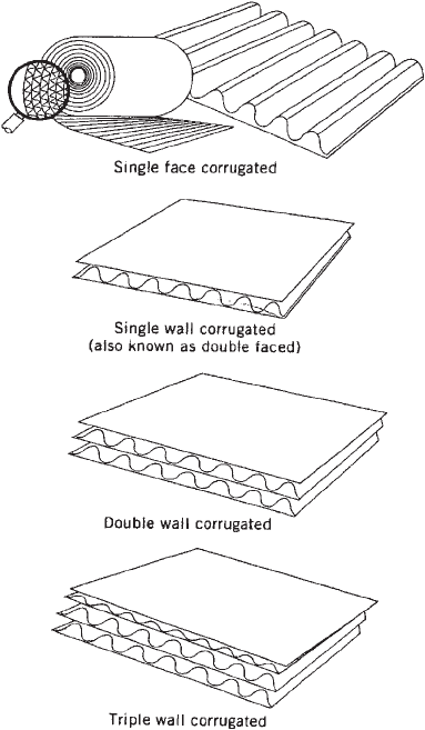
BOARD CONSTRUCTION
Corrugated board is a sandwich of one or more linerboard
sheets adhered to a fluted medium. Single-face construc-
tion incorporates one linerboard adhered to the medium.
Double-face, better known as single-wall, has a linerboard
adhered to both sides of the medium. Additional media
and linerboards yield double-wall and triple-wall (see
Figure 1).
Combinations of linerboard grades and flute configura-
tions are used to generate the many variations of corru-
gated board. Liner weights are increased to improve board
bursting and stacking strength, and flutes are modified to
accommodate various compression, stack, and printing
Figure 1. Various examples of corrugation.
BOXES, CORRUGATED 163

features. Two important requirements of corrugated board
are flat crush and stacking strength. Flat crush measures
the pounds per square inch (psi) resistance to pressure
applied at a 901 angle to a horizontal sheet, thus establish-
ing the rigidity of the flute structure. This property is
changed by varying the flute outline and linear density. It
can also be revised by changing the basis weight of the
fluted medium. Flat crush supplies the internal resistance
to squeezing forces such as feed rollers in presses and
gluers. It also supplies resistance to gravitational forces
imposed upon bottom sheets in stacks and bottom cartons
in units.
Stacking strength measures the ability of a vertical
panel to resist bowing, buckling, or collapsing from pres-
sure exerted in line with that panel. This is regulated by
varying the linerboard weights, changing flute heights, or
both. Stacking strength is probably the most sought-after
characteristic in corrugated cartons.
Flutes
Flutes are most essential to the characteristic of corru-
gated board. They supply the rigidity to the board that
imparts strength with minimal weight and density. Flut-
ing makes the product economical. Flutes are designed by
height (thickness) and density (number per linear foot).
Higher flutes produces a physically stronger columnar
stack in line with the flutes. Denser flutes—that is, flutes
that present more images per linear foot—produce more
resistance across the flutes. C is the most used flute size,
followed by B and E. The C flute is considered a compro-
mise between A and B. Other, minimally used flutes
include J (jumbo), which is larger than the others, as the
name suggests; S flute; and F flute, which is the lowest
flute height.
Higher (less dense) flutes in addition to stacking
strength provide softer cushion characteristics, while
lower (more dense) flutes provide greater flat crush
resistance, smoother print surfaces, and crisper score
lines. Flutes are often used in combinations such as BC
double wall, which provides an overlap of required
characteristics. B and C flutes are the most com-
monly produced flutes, and E is considered sparingly.
Flute selection is determined by shipper needs. A fragile-
decorations shipper would choose C flute for its stacking
strength and cushioning qualities. A canned beverage
filler would choose B flute for its end-to-end compres-
sion attributes; and a point-of-purchase display designer
would select E flute for its superior printing surface. (See
Table 1.)
MULLEN VERSUS EDGE CRUSH
Carrier regulating agencies require a board upgrade to
accommodate increased loads and increased box sizes
analogous to the idea that a 3/4-in. (19-mm) plywood sheet
is stronger than a 1/4-in. (6.35-mm) sheet. Paper mills
fulfill this requirements by producing various-weight liner
grades, corrugated converters combine board using proper
heavier grades to accommodate the need for stronger
containers.
Liner Grades
The universally accepted test for corrugated board has
been the Mullen test (TAPPI test method T-810), which
measures the resistance of the board to withstand a
puncturing pressure measured in pounds per square
inch (psi) or metric kilopascals (kPa). Linerboard grades
have been manufactured to meet specific Mullen require-
ments. Increased Mullen demands increased linerboard
strength, which is accomplished by increasing the mass of
the linerboard measured in pounds per thousand square
feet (lb/1000 ft
2
) (kg/90 m
2
).
A major modification to containerboard was initiated in
the 1980s, when paper mills developed a process that
enhanced linerboard material, giving it an ability to with-
stand crush or compression examinations at lower basis
weights. Table 2 compares STFI crush performance of
standard to high-performance liners. Note the improved
STFI in high-performance liner.
The product high-performance linerboard provides a
serious potential for user satisfaction and improved eco-
nomics. New linerboard concepts prompted the corrugated
industry trade associations to sponsor proposals to truck-
and rail-carrier committees to consider classifications
recognizing edge crush as a test criteria. Proponents for
the new test methods argued that edge crush is more
customer-oriented and that it permits more latitude for
manufacturers to design and supply boxes that meet
customer performance criteria. Rules committees of truck
and rail carriers accepted the proposals, and in 1991 they
approved the edge-crush test (ECT) as an alternative test
method for containerboard.
Edge-crush Test
This measures the resistance of the containerboard to
edgewise compression. Ring-crush and STFI tests mea-
sure the resistance of the linerboard and medium. These
tests are performed to give the linerboard and corru-
gated manufacturers relative material comparisons. The
Table 1. Standard U.S. Corrugated Flutes
a
Flute Designation Flutes per Linear Foot Flutes per Linear Meter Flute Thickness, in. (mm) Flutes per Cross Section
A flute 3373 108710 3/16 (4.8)
B flute 4773 154710 1/8 (3.2)
C flute 3973 128710 5/32 (4.0)
E flute 9074 295713 1/16 (1.6)
a
Corrugator equipment manufacturer’s single-face flute roll dimension may vary slightly to accommodate user preference.
164 BOXES, CORRUGATED

edge-crush test includes the value of the medium’s resis-
tance to compression as well as the linerboard. It should
be noted that these tests can, and are, performed on
standard weight liners as well as on high-performance
liners (see Edge-crush concept).
Medium Grades
General industrial principle requires use of the same
medium weight (26 lb/1000 ft
2
) (11.7 kg/90 m
2
) for all board
grades; that is, liner weights change to generate increas-
ing board tests, but the medium remains the same. There
are some approved exceptions that call for upgrading
medium to improve flat crush and moisture resistance.
Two upgraded medium weights are 33 and 40 lb.
REGULATIONS
Freight carriers and government agencies control the
regulations for the container industry. The major regula-
tion is encompassed in Rule 41 (Uniform Freight Classi-
fication) established by the National Railroad Freight
Committee (2). This regulation is closely paralled by
Item 222 (National Motor Freight Carriers). Table 3 out-
lines minimum standards. Triple-wall and solid-fiber stan-
dards have not been included in this chart.
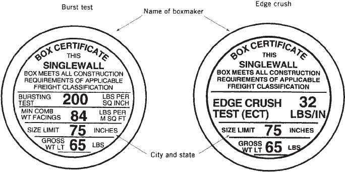
Rules prescribed by these agencies outline require-
ments that determine proper liner weights and manufac-
turing specifications. All corrugated boxes made to
conform to the regulations carry a printed certificate
identifying the boxmaker and appropriate board grade
as shown in Figure 2. Note the apparent difference
between the burst-test and the edge-crush certificates.
Table 2. STFI Crush Performance of Standard to High-
Performance Liners
Liner Basis Weight STFI
lb/1000 ft
2
(kg/90 m
2
) lb/in. width (kg/cm width)
26 11.8 12 13.9
33 14.9 15 17.4
38 17.2 17 19.7
42 19.0 19 22.0
69 31.2 29 33.6
90 40.7 38 44.0
Medium-Performance Liner
26 11.8 11 12.8
33 14.9 15 17.4
40 18.0 19 22.0
High-Performance Liner
35 15.8 20.3 23.6
45 20.3 27.5 31.9
57 25.8 33.7 39.1
72 32.6 45.0 52.2
Table 3. Minimum Standards for Construction of Corrugated Boxes
a
Table A Table B
Maximum Weight of
Box and Contents, lb
(kg)
Maximum Outside
Dimensions, Length,
Width, and Depth
Added Inches (cm)
Minimum Bursting
Test, Single-Wall,
Double-Wall, psi (See
Note 1) (MPa)
Minimum Combined
Weight of Facings,
Including Center
Facing(s) of Double-
Wall, lb/1000 ft
2
(g/m
2
)
Minimum ECT, lb/in.,
Width (See Note 2) (kg/
cm width)
Single-Wall Corrugated Fiberboard Boxes
20 (9) 40 (102) 125 (0.862) 52 (254) 23 (26.3)
35 (16) 50 (127) 150 (1.034) 66 (322) 26 (29.7)
50 (22) 60 (152) 175 (1.206) 75 (366) 29 (33.1)
65 (29) 75 (190) 200 (1.379) 84 (410) 32 (36.5)
80 (36) 85 (216) 250 (1.723) 111 (542) 40 (45.7)
95 (43) 95 (241) 275 (1.896) 138 (674) 44 (50.3)
120 (54) 105 (267) 350 (2.412) 180 (879) 55 (62.8)
Double-Wall Corrugated Fiberboard Boxes
80 (36) 85 (216) 200 (1.379) 92 (449) 42 (48)
100 (45) 95 (241) 275 (1.896) 110 (537) 48 (54.9)
120 (54) 105 (267) 350 (2.412) 126 (615) 51 (58.2)
140 (63) 110 (279) 400 (7.757) 180 (878) 61 (69.6)
160 (72) 115 (292) 500 (3.445) 222 (1084) 71 (81.1)
180 (81) 120 (305) 600 (4.135) 270 (1318) 82 (93.6)
a
Note 1—Burst test: (a) Tests to determine compliance with the bursting test requirements of Table A must be conducted in accordance with Technical
Association of Pulp and Paper Industry (TAPPI), Official Test Method T-810; (b) a minimum of six bursts must be made three from each side of the board, and
only one burst test will be permitted to fall below the specified minimum value. Board failing to pass the foregoing test will be accepted if in a retest consisting
of 24 bursts (12 from each side of the board), not more than four burst tests fall below the specified minimum value. Note 2—Edge-crush test: (a) Tests to
determine compliance with the edge crush requirements of Table B must be conducted in accordance with Technical Association of Pulp and Paper Industry
(TAPPI), Official Test Method T-811; (b) a minimum of six tests must be made and only one test is permitted to fall below the specified minimum value, and
that one test cannot fall below the specified minimum value by more than 10%. Board failing to pass the forgoing will be accepted if in a retest consisting of 24
tests, not more than four tests fall below the specified minimum value, and none of those tests fall below the specified minimum value by more than 10%.
BOXES, CORRUGATED 165
Several other regulatory agencies are included depend-
ing on shipper requirements, including
Department of Transportation—Code of Federal Regu-
lations No. 49 (Transportation)-Pointing specifically
at hazardous materials
International Air Transport Authority (IATA)—con-
cerned with air transport
International Maritime Authority—water cargo
United Parcel Service (UPS)—ground deliveries of
o150 lb
U.S. Postal Service—Domestic Mail Manual
CONVERTING OPERATIONS
Corrugated fiberboard boxes are manufactured in a cor-
rugated board plant or in a sheet feeder plant. The
corrugated board plant consists of the corrugator, which
produces flat sheets of corrugated fiberboard, and the
converting equipment where the corrugated sheet is con-
verted into corrugated board boxes by printing, cutting,
scoring, and gluing. Sheet feeder plants are smaller
factories that convert board into packaging for shorter
run length orders, for quick deliveries, and for a local
market.
Contemporary box plants vary widely in size and
capability. A small sheet plant may ship one truckload of
cartons per day while the megacontainer plant will ship 50
truckloads per day. Corrugated requirements are so di-
verse that a wide variety of company sizes is a desirable
asset to the industry.
Corrugator
This is the major piece of equipment in a box plant. The
machine converts mill-supplied roll stock (linerboard and
medium) into flat sheets. It varies from 50 to 100 in. plus
(12.7–25.4 m) in width, and most are over 300 ft (91.5 m)
long. Wide computer-managed corrugators operating at
speeds of up to 1000 lineal feet per minute are capable of
producing four truckloads of corrugated board per hour.
The single-facer (wet end) of the corrugator converts
the medium into fluted paper and adheres it to the
inside liner of the corrugated sandwich. Next, a double
backer roll is applied as the outside liner, and finally the
sandwich is run over dryer plates and delivered to the dry
end. Cross-corrugation scores may be applied and the
board is trimmed into two-dimensional blanks in prepara-
tion for delivery to the plant for further conversion into
a box.
Scheduling (trimming) a corrugator requires skill and
training because variations of liner combinations, quan-
tity requests, and blank dimensions are endless. Modern
computer-trimmed corrugators are capable of producing
several hundred setups per day.
Printer-Slotters
These machines print, slot, and score flat banks in pre-
paration for folding and joining into finished boxes. Sized
blanks are delivered from the corrugator prescored for flap
and depth dimension. The operator, generally one of a two-
or three-worker crew, sets scoring and slotting heads at
proper dimensions to cut required length, width, and joint
dimensions into the carton. The operator then hangs the
premounted printing plates on the print cylinders, fills the
ink wells with desired colors, and begins production.
These machines are referred to by the number of colors
they are capable of printing in one pass plus cylinder
diameter and machine width. Small-dimension machines
are obviously better suited for producing small boxes, and
so on. A majority of presses today are two-color; however,
presses in up to six colors are available.
Corrugated printer-slotters are letterpress printers;
however, most current equipment is a flexographic varia-
tion that incorporates the use of an analox roller with
water-base inks versus the old doctor and impression
rollers with oil-based ink. Flexographic printing offers
many advantages over letterpress, including operating
speed, clarity, registration, trapping, drying, and cleanup.
Printer-slotters employing flexographic printing can pro-
duce an average size-box (e.g., a 24/12-oz beverage box) at
approximately 15,000 per hour.
Figure 2. Boxmaker certificate.
166 BOXES, CORRUGATED
Flexofolder-Gluer
The Flexofolder-Gluer (FFG) incorporates the addition of
an automatic folder–gluer system with the printing unit,
which permits the completion of most cartons on one
machine. The equipment has been available since the
1960s, when flexographic printing with high-speed drying
made it possible for cartons to be folded immediately after
printing without smearing. These machines may also be
equipped with automatic bundeling and unitizing sys-
tems. The most advanced FFG can run up to speeds of
26,000 boxes per hour. Boxes can be produced for any
application.
Folder–Gluers
These are designed to finish boxes in a straight line or
right angle. Both are extremely efficient at folding panels
and applying adhesive to produce finished cartons that
require minimum or no final sealing. Predecorated,
slotted, and or die-cut blanks are belt fed through the
folding sections; glue is applied at required spots; and
finished cartons are stacked at the finish end. Most
equipment is designed to accept a wide variety of sizes
both in the machine direction and across the machine.
Die Cutters
Die cutters are required for all parts that are scored or
slotted other than 901 or in line with press direction.
Intricate die cut interior parts and box designs are a
very common part of the industry.
Flatbed die cutters are designed to produce accurate
products. They vary from small hand-fed machines that
are limited in speed to the operators performance (about
500 blanks per hour) to high-performance automatic
equipment that include multicolor printing selections.
Flatbed cutting dies are reasonably priced. The process
for flatbed die cutting closely resembles cookie cutting.
The die board is locked into a chase that holds it in a firm
position. Corrugated board is registered under the die;
and the machine is closed, striking the die impression into
the board.
Rotary die cutters are best used to produce parts at
high speeds. They are not as accurate as flatbed machines;
however, they can be designed to accept large blanks.
Rotary cutting rule is inserted into curved plywood and
then locked onto the die-cutting cylinder. An impression is
made into the board when a blank is passed between the
cut die cylinder and an opposing thick polyblanketed
impression cylinder.
Slitters
Slitters have a series of wide rotating shafts to which
scoring and slitting collars (heads) are attached. These
heads can be moved by the operator to change dimensions.
Most slitters are manually fed; however, some are
equipped with automatic feed sections. Slitters are used
to reduce large sheets to smaller blank dimensions, add
scores to existing blanks, and prepare small runs for
further processing. Slitters are very versatile machines.
Small sheet plants may be totally equipped with a slitter a
printer–slotter and a taper.
Partition Slotters
These machines slot corrugated pads in preparation for
assembly into partitions.
Partition Assemblers
These machines automatically assemble slotted racks into
cell-divided partitions for use in separating delicate parts
such as glass bottles.
Tapers
These machines apply tape fed from rolls onto prefolded
cartons to form a manufacturer’s joint. Standard tape
widths are 2 in. (5.08 cm) or 3 in. (7.62 cm). Tapers are
handfed semiautomatic or hopper-fed automatic. The
machine is an economical piece of equipment that can be
adjusted and set very quickly. Taped joints represent a
minimal amount of todays production because of their
relatively slow production speeds and higher costs com-
pared with glued joints. Glued joints also perform better in
regulatory transit tests.
Stitchers
These devices apply staples cut from a roll and are driven
into the joints of prefolded boxes. Stitched joints have
limited use in today’s market; they are used mostly with
government-grade boards and specialty wet-strength
containers.
Coaters
These machines are operated at box plants or, in many
cases, at specialty plants that process coatings on finished
containers. These specialty plants function as a separate
entity to the corrugated industry; that is, they seek custo-
mers for their process, mostly from the fish, poulty, and
produce industries; purchase finished containers from cor-
rugated converters; and add the required coatings (waxes
and plastics) to the containers. The industry specializes in
wet-strength and moisture-barrier containers.
Curtain coaters feed box blanks under a curtain of
liquid coating (molten poly) that coats one side of the
blank and passes it to a drying section. Some coaters are
capable of flipping the blank to deposit a coating on both
sides. Cascaders pour wax coatings onto finished contain-
ers. Wax dippers immerse finished containers into tanks of
molten wax and then hang them to dry. The process looks
very much like your local laundry.
Laminators
Litholaminators have
become an important
adjunct to the
high-graphics corrugated producer. This equipment rolls
adhesive onto a printed litholabel, registers the label
under the substrate, drops the substrate onto the label,
and rolls the combined stock to achieve 100% adhesion
and eliminate air bubbles. Litholaminators are designed
to feed flat banks, including joined (knocked-down) boxes.
BOXES, CORRUGATED 167