Yu W., LaBoube R.A. Cold-Formed Steel Design
Подождите немного. Документ загружается.

BENDING STRENGTH AND DEFLECTION 115
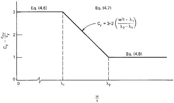
Figure 4.15 Factor C
y
for stiffened compression elements without intermediate stiffeners.
edge and tension at the other longitudinal edge:
C
y
=
⎧
⎪
⎪
⎪
⎪
⎨
⎪
⎪
⎪
⎪
⎩
3.0 λ ≤ λ
3
(4.9a)
3 − 2[(λ − λ
3
)/(λ
4
− λ
3
)]
λ
3
≤ λ ≤ λ
4
(4.9b)
1 λ ≥ λ
4
(4.9c)
where λ is the slenderness factor defined in Section
3.5.1.1,
λ
3
= 0.43 (4.9d)
λ
4
= 0.673(1 + ψ) (4.9e)
and ψ is defined in Section B3.2 of the specifica-
tion.
ii. Unstiffened compression elements under a stress
gradient causing compression at both longitudinal
edges:
C
y
= 1 (4.9f)
iii. Unstiffened c ompression elements under uniform
compression:
C
y
= 1 (4.9g)
3. Multiple-stiffened compression elements and
compression elements with edge stiffeners
C
y
= 1.0 (4.10)
No limit is placed on the maximum tensile strain in the
North American Specification.
For the above requirements, Eqs. (4.9a)–(4.9g) were
added in 2004 for sections having unstiffened elements
under a stress gradient.
1.343
These recently added design
equations are based on the research work conducted by
Bamback and Rasmussen at the University of Sydney on I-
and plain channel sections in minor-axis bending.
4.194,4.195
The C
y
values are dependent on the stress ratio ψ and
slenderness factor λ of the unstiffened element with the
stress gradient determined in Section 3.5.2.2.
On the basis of the maximum compression strain ε
cu
allowed in Eq. (4.5), the neutral axis can be located by using
Eq. (4.11), and the nominal moment M
n
can be determined
by using Eq. (4.12) as follows:
σdA= 0 (4.11)
σy dA = M
n
(4.12)
where σ is the stress in the cross section.
For hat sections Reck, Pekoz, and Winter gave the
following equations for the nominal moments of sections
with yielded tension flange and sections with tension flange
not yielded:
(a) Sections with Yielded Tension Flange at Nominal
Moment.
4.1
For the stress distributions shown in
Fig. 4.16, Eqs. (4.13)–(4.18) are used for computing
the values of y
c
, y
t
, y
p
, y
cp
, y
tp
,andM
n
.Forthe
purpose of simplicity, midline dimensions are used in
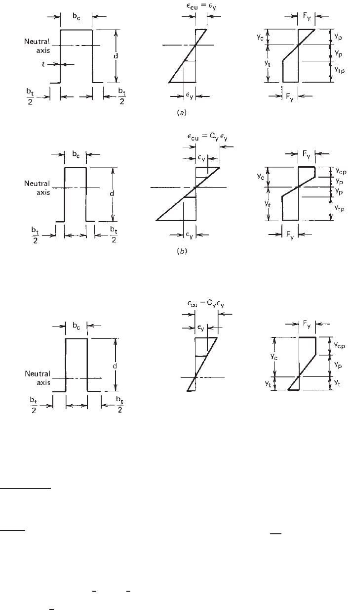
116 4 FLEXURAL MEMBERS
Figure 4.16 Stress distribution in sections with yielded tension flange at nominal moment.
4.1
Figure 4.17 Stress distribution i n sections with tension flange not yielded at nominal moment.
4.1
the calculation:
y
c
=
b
t
− b
c
+ 2d
4
(4.13)
y
t
= d − y
c
(4.14)
y
p
=
y
c
ε
cu
/ε
y
(4.15)
y
cp
= y
c
− y
p
(4.16)
y
tp
= y
t
− y
p
(4.17)
M
n
= F
y
t
b
c
y
c
+ 2y
cp
y
p
+
1
2
y
cp
+
4
3
(y
p
)
2
+2y
tp
y
p
+
1
2
y
tp
+ b
y
y
t
(4.18)
(b) Sections with Tension Flange Not Yielded at Nominal
Moment.
4.1
For the stress distribution shown in
Fig. 4.17, y
c
is computed from the following quadratic
equation:
y
2
c
2 −
1
C
y
− C
y
+ y
c
(b
c
+ 2C
y
d + C
y
b
t
)
− (C
y
d
2
+ C
y
b
t
d) = 0 (4.19)
Subsequently, the values of y
t
, y
p
,andy
cp
can be
computed from Eqs. (4.14), (4.15), and (4.16), respec-
tively.
BENDING STRENGTH AND DEFLECTION 117
If y
p
>y
t
, then the case in part (b) above applies and the
nominal moment M
n
is computed as follows:
M
n
= F
y
t
b
c
y
c
+ 2y
cp
y
p
+
y
cp
2
+
2
3
(y
p
)
2
+
2
3
(y
t
)
2
σ
t
F
y
+ b
y
y
t
σ
t
F
y
(4.20)
In Eq. (4.20), σ
t
= F
y
C
y
y
t
/y
c
.
It should be noted that according to Section C3.1.1 of
Supplement 2004 to the North American Specification, Eqs.
(4.18) and (4.20) can be used only when the following
conditions are met:
1. The member is not subject to twisting or to lateral,
torsional, or flexural–torsional buckling.
2. The effect of cold work of forming is not included in
determining the yield stress F
y.
3. The ratio of the depth of the compression portion of
the web to its thickness does not exceed λ
1.
4. The shear force does not exceed 0.35F
y
for ASD and
0.6F
y
for LRFD and LSD times the web area (ht for
stiffened elements or wt for unstiffened elements).
5. The angle between any web and the vertical does not
exceed 30
◦
.
It should also be noted that, when applicable, effective
design widths should be used in the calculation of sectional
properties.
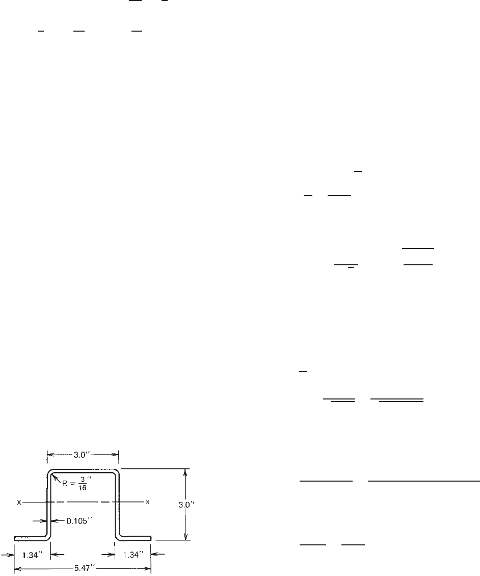
Example 4.5 For the hat section (3 × 3 × 0.105 in.)
shown in Fig. 4.18, determine the allowable moment (M
a
)
about the x axis for the ASD method and the design moment
(φ
b
M
n
) for the LRFD method. Consider the inelastic reserve
capacity according to Section C3.1.1 of the 2007 edition
of the North American Specification. Use F
y
= 33 ksi and
assume that lateral support is adequately provided.
Figure 4.18 Example 4.5.
SOLUTION
A. ASD Method
1. Dimensions of Section. By using the midline dimen-
sions and square corners, the widths of compres-
sion and tension flanges and the depth of webs are
computed as follows:
a. Width of compression flange:
b
c
= 3 − 0.105 = 2.895 in.
b. Width of tension flange:
b
t
= 2(1.34 − 0.105/2) = 2.576 in.
c. Depth of webs:
d = 3 − 0.105 = 2.895 in.
All dimensions are shown in Fig. 4.19a. Check the
effective width of the compression flange:
w = 3 − 2(
3
16
+ 0.105) = 2.415 in.
w
t
=
2.415
0.105
= 23
k = 4.0
f = F
y
= 33 ksi
λ =
1.052
√
4
(23)
33
29,500
= 0.405 < 0.673
b = w = 2.415 in.
Therefore, the compression flange is fully effective.
2. Strain Diagram. The w/t ratio of the stiffened
compression flange is given as
w
t
= 23
λ
1
=
1.11
F
y
/E
=
1.11
√
33/29,500
= 33.2
Since w/t < (λ
l
= 33.2), according to Eq. (4.6), C
y
=
3.0. Therefore, ε
cu
= 3ε
y
,asshowninFig.4.19b.
3. Stress Diagram. The values of y
c
, y
t
, y
p
, y
cp
,andy
tp
are computed by using Eqs. (4.13)–(4.17) as follows:
y
c
=
b
t
− b
c
+ 2d
4
=
2.576 − 2.895 +2 × 2.895
4
= 1.368 in.
y
t
= d − y
c
= 2.895 − 1.368 = 1.527 in.
y
p
=
y
c
ε
cu
/ε
y
=
1.368
3
= 0.456 in.
y
cp
= y
c
− y
p
= 1.368 − 0.456 = 0.912 in.
y
tp
= y
t
− y
p
= 1.527 − 0.456 = 1.071 in.
118 4 FLEXURAL MEMBERS
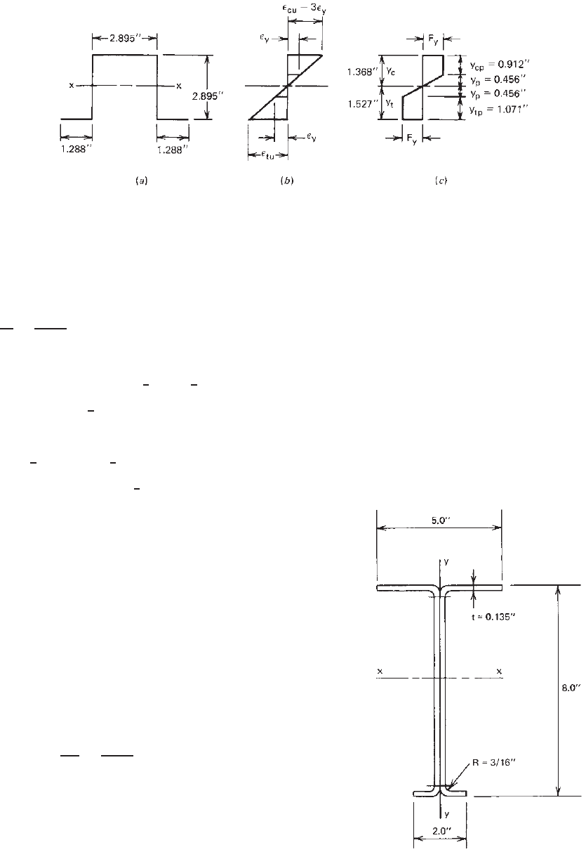
Figure 4.19 Stress distribution: (a) midline dimensions; (b)strain;(c) stress.
All dimensions are shown in Fig. 4.19c.
4. Nominal Moment M
n
. In order to utilize the inelastic
reserve capacity, the North American Specification
requirements must be checked:
y
c
t
=
1.368
0.105
= 13.03 <(λ
1
= 33.2) OK
Therefore, the nominal moment is
M
n
= F
y
t[b
c
y
c
+ 2y
cp
(y
p
+
1
2
y
cp
) +
4
3
(y
p
)
2
+ 2y
tp
(y
p
+
1
2
y
tp
) + b
t
y
t
]
= 33(0.105)[(2.895 × 1.368) + 2(0.912)(0.456
+
1
2
× 0.912) +
4
3
(0.456)
2
+ 2(1.071)(0.456 +
1
2
× 1.071)
+ (2 × 1.288)(1.527)]
= 41.43 in. -kips
5. Yield Moment M
y
. B ased on the method illustrated in
Example 4.3, S
e
for the given hat section is 0.992 in.
3
Therefore
M
y
= S
e
F
y
= 0.992(33) = 32.74 in.-kips
1.25M
y
= 1.25(32.74) = 40.93 in.-kips
6. Allowable Moment M
a
. Because M
n
exceeds 1.25M
y
,
use
M
n
= 1.25M
y
= 40.93 in.-kips
M
a
=
M
n
b
=
40.93
1.67
= 24.51 in.-kips
B. LRFD Method.
The nominal moment for the LRFD method is the same as
that computed for the ASD method. From item A above,
the nominal moment about the x axis of the hat section is
M
n
= 40.93 in.-kips
Based on Section 4.2.1 in this volume or C3.1.1 of the
North American specification, the design moment for the
hat section having a stiffened c ompression flange (φ
b
= 0.95) is
φ
b
M
n
= 0.95(40.93) = 38.88 in.-kips
Example 4.6 For the I-section with unequal flanges as
shown in Fig. 4.20, determine the allowable moment (M
a
)
about the x axis for the ASD method and the design moment
(φ
b
M
n
) for the LRFD method. Consider the inelastic reserve
capacity and use F
y
= 50 ksi. Assume that the lateral
support is a dequately provided to prevent lateral buckling.
Figure 4.20 Example 4.6.
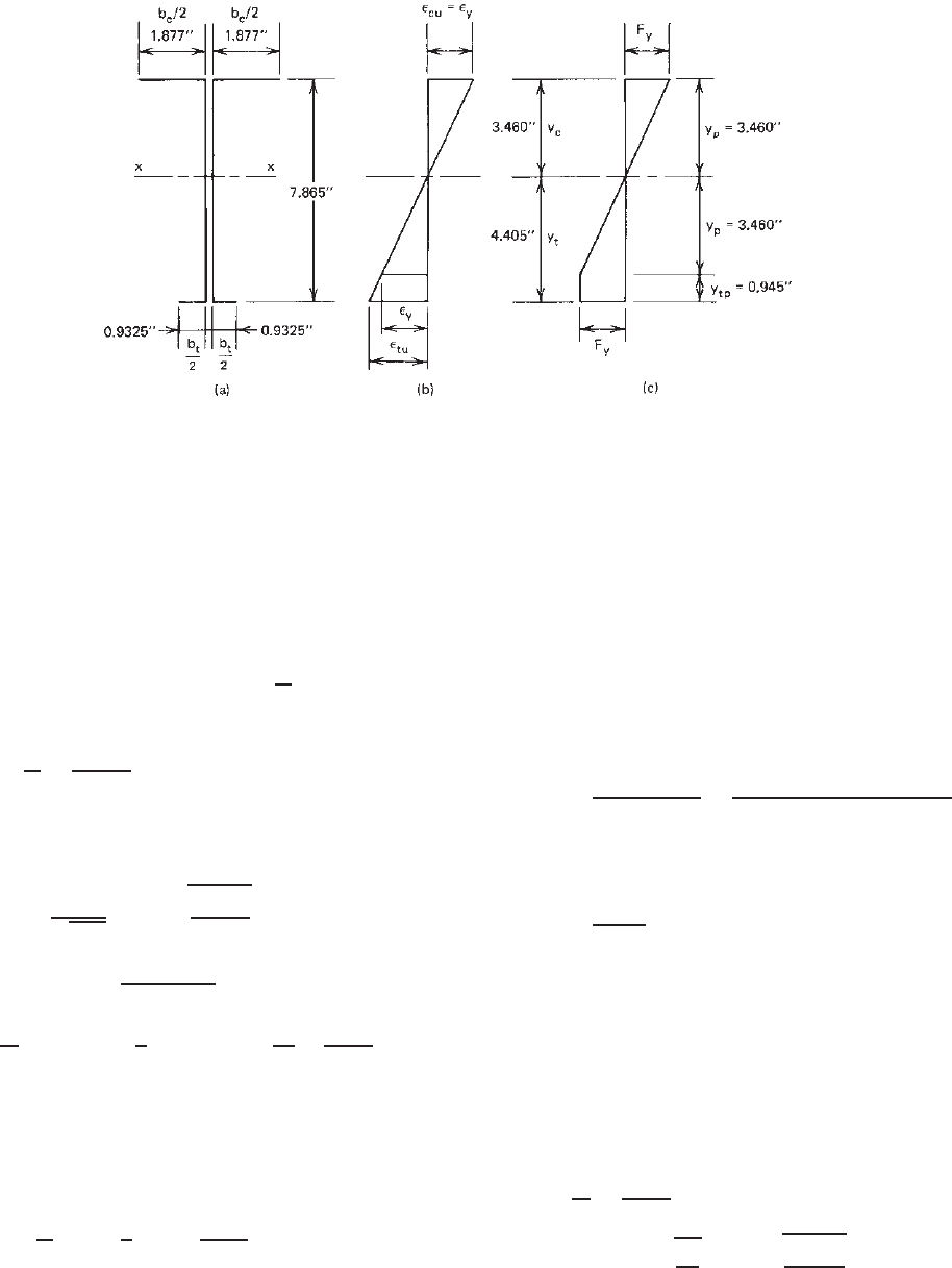
BENDING STRENGTH AND DEFLECTION 119
Figure 4.21 Stress distribution: (a) midline dimensions; (b)strain;(c) stress.
SOLUTION
A. ASD Method
1. Dimensions of Section. By using the midline dimen-
sions and square corners, the widths of compres-
sion and tension flanges and the depth of webs are
computed as follows: The flat width of the unstiffened
compression flange according to Section 3.2 is
w = 2.5 − (R + t) = 2.5 − (
3
16
+ 0.135)
= 2.1775 in.
w
t
=
2.1775
0.135
= 16.13
For f = F
y
= 50 ksi in the top fiber and k = 0.43 for
the unstiffened flange,
λ =
1.052
√
0.43
(16.13)
50
29,500
= 1.065 > 0.673
b = ρw =
1 − 0.22/λ
λ
w = 1.622 in.
b
c
2
= b + (R +
t
2
) = 1.622 +
3
16
+
0.135
2
= 1.877 in.
b
c
= 3.754 in.
The width of the tension flange is determined as
b
t
2
= 1 −
t
2
= 1 −
0.135
2
= 0.9325 in.
b
t
= 1.865 in.
The depth of the webs is given as
d = 8.0 − t = 8.0 − 0.135 = 7.865 in.
All midline dimensions are s hown in Fig. 4.21a.
2. Strain Diagram. For an unstiffened compression
flange under uniform compression, C
y
= 1.0. There-
fore
ε
cu
= ε
y
,asshowninFig.4.21b.
3. Stress Diagram. The values of y
c
, y
t
, y
p
,andy
tp
are
computed by using Eqs. (4.13)–(4.17) as follows:
y
c
=
b
t
− b
c
+ 2d
4
=
1.865 − 3.754 +2(7.865)
4
= 3.46 in.
y
t
= d − y
c
= 7.865 − 3.46 = 4.405 in.
y
p
=
y
c
ε
cu
/ε
y
= y
c
= 3.46 in.
y
cp
= 0
y
tp
= y
t
− y
p
= 4.405 − 3.46 = 0.945 in.
All dimensions are shown in Fig. 4.21c.
4. Nominal Moment. In order to satisfy the North Amer-
ican requirements for using the inelastic reserve
capacity, check the y
c
/t ratio against the limit of λ
1
:
y
c
t
=
3.46
0.135
= 25.63
λ
1
= 1.11
F
y
E
= 1.11
50
29,500
= 26.96
120 4 FLEXURAL MEMBERS
Since y
c
/t < λ
l
, OK. Therefore, the nominal
moment is determined as
M
n
= F
y
t[b
c
y
c
+
4
3
(y
p
)
2
+ 2y
tp
(y
p
+
1
2
y
tp
) + b
t
y
t
]
= 50(0.135)[(3.754 × 3.46) +
4
3
(3.46)
2
+ 2(0.945)(3.46 +
1
2
× 0.945)
+ 1.865(4.405)]
= 301.05 in. -kips
5. Yield Moment. Based on the method illustrated in
Example 4.1, the effective yield moment M
y
is
M
y
= 248.0in.-kips
1.25M
y
= 310.0in.-kips
6. Nominal Moment and Allowable Moment. Because M
n
is less than 1.25M
y
,useM
n
for the nominal moment,
that is,
M
n
= 301.05 in.-kips
The allowable design moment is
M
a
=
M
n
b
=
301.05
1.67
= 180.27 in.-kips
B. LRFD Method.
The nominal moment for the LRFD method is the same as
that computed for the ASD method. From item A above,
the nominal moment about the x axis of the I-section with
unequal flanges is
M
n
= 301.05 in.-kips
Based on Section 4.2.1 or Section C3.1.1 of the North
American Specification, the design moment for the
I-section having an unstiffened compression flange (φ
b
= 0.90) is
φ
b
M
n
= 0.90(301.05) = 270.95 in.-kips
4.2.2.4 Economic Design for Bending Strength The
above discussion and design examples are based on the fact
that the allowable design moment is determined for a given
section for which the dimensions are known. In the design
of a new section, the dimensions are usually unknown
factors. The selection of the most favorable dimensions can
be achieved by using the optimum design technique. This
is a very complex nonlinear problem which can only be
solved by computer analysis.
1.247
However, if the depth and
the thickness of the section are known, previous study has
shown that the maximum moment-to-weight ratio usually
occurs in the neighborhood of the flange width determined
by Eq. (4.21) or (4.22) as applicable:
1. For unstiffened compression flanges,
w = 0.43t
E
f
(4.21)
2. For stiffened c ompression flanges supported by a web
on each longitudinal edge,
w = 1.28t
E
f
(4.22)
where w = flat width for compression flange
t = thickness of steel
E = modulus of elasticity
f = maximum compressive edge stress in the
element without considering the safety
factor
The economic design of continuous beams and long-span
purlins is discussed in Refs. 4.11 and 4.12.
4.2.2.5 Deflection of Flexural Members For a given
loading condition, the deflection of flexural members
depends on the magnitude, location, and type of the
applied load, the span length, and the bending stiffness EI ,
in which the modulus of elasticity in the elastic range is
29.5 × 10
3
ksi (203 GPa or 2.07×10
6
kg/cm
2
)andI is the
moment of inertia of the beam section.
Similar to the bending strength calculation, the determi-
nation of the moment of inertia I for calculating the deflec-
tion of steel beams is based on the effective areas of the
compression flange, edge stiffer, and beam web, for which
the effective widths are computed for the compressive stress
developed from the bending moment. If the compression
flange, edge stiffer, and beam web are fully effective, the
moment of inertia is obviously based on the full section. In
this case, the moment of inertia is a constant value along
the entire beam length. Otherwise, if the moment of inertia
is on the basis of the effective areas of the compression
flange, edge stiffener, and/or beam web, the moment of
inertia may vary a long the beam span because the bending
moment usually varies along the beam length, as shown in
Fig. 4.22.
In the design of thin-walled cold-formed steel sections,
the method to be used for deflection calculation is based on
the accuracy desired in the analysis. If a more exact deflec-
tion is required, a computer program or a numerical method
may be used in which the beam should be divided into a
relatively large number of elements according to variable
moments of inertia. The deflection calculation for such a
beam is too complicated for hand calculation. On the other
hand, if an approximate analysis is used, the deflection of
a simply supported beam may be computed on the basis of
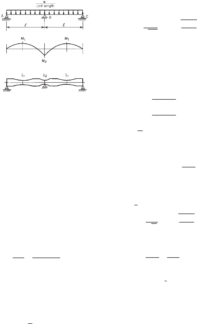
BENDING STRENGTH AND DEFLECTION 121
Figure 4.22 Bending moment and variable moments of inertia
for two-span continuous beam under uniform load.
4.14
a constant moment of inertia determined for the maximum
bending moment. The error so introduced is usually small
and on the conservative side.
3.13
For continuous spans, the
deflection of the beam may be computed either by a rational
analysis
4.13
or by a method using a conventional formula
in which the average value of the positive and negative
moments of inertia I
1
and I
2
will be used as the moment of
inertia I .
4.14
This simplified method and other approaches
have been used in Refs. 4.6 and 4.7 for a nonlinear analysis
of continuous beams.
Example 4.7 Determine the moment of inertia of the
I-Section (Fig. 4.2) to be used for deflection calculation
when the I-section is loaded to the allowable moment as
determined in Example 4.1 for the ASD method.
SOLUTION From Example 4.1, the allowable moment
for the given I-section is 187.0 in.-kips. The estimated
compressive stress in the top fiber under the allowable
moment is
f =
My
cg
I
x
=
187.0(4.063)
25.382
= 29.93 ksi
The same stress of f = 29.93 ksi will be assumed in
the calculation of the effective design width for deflection
calculation.
By using Eqs. (3.45)–(3.47) and the same procedure
employed in Example 4.1, the effective width b
d
of the
unstiffened flange can be computed as follows:
w = 1.6775 in.
w
t
= 12.426
k = 0.43
f
d
= 29.93 ksi
λ =
1.052
√
0.43
(12.426)
29.93
29,500
= 0.635 < 0.673
ρ = 1.0
b
d
= w = 1.6775 in.
Using the full width of the compression flange and
assuming the web is fully effective, the neutral axis
is located at the middepth (i.e., y
cg
= 4.0in.). Prior to
computing the moment of inertia, c heck the web for effec-
tiveness as follows:
f
1
= 29.93
4 − 0.3225
4
= 27.52 ksi (compression)
f
2
= 29.93
4 − 0.3225
4
= 27.52 ksi (tension)
ψ =
f
2
f
1
= 1.0
k = 4 + 2(1 − ψ)
3
+ 2(1 − ψ) = 24.0
As in Example 4.1, h
0
/b
0
= 4. Use Eq. (3.55a),
b
1
=
b
e
3 + ψ
where b
e
is the effective width of the web determined
in accordance with Eqs. (3.41) through (3.44) with f
1
substitued for f and k = 24.0 as follows:
h
t
= 54.48
λ =
1.052
√
24
(54.48)
27.52
29,500
= 0.357 < 0.673
ρ = 1.0
b
e
= h = 7.355 in.
b
1
=
b
e
3 + ψ
=
7.355
3 + 1
= 1.839 in.
Since ψ>0.236,
b
2
=
1
2
b
e
= 3.6775 in.
b
1
+ b
2
= 1.839 + 3.6775 = 5.5165 in.
Since b
1
+ b
2
is greater than the compression portion of
the web of 3.6775 in., the web is fully effective as assumed.
Because both the compression flange and the web are fully
effective, the moment of inertia I
x
of the full section can
be computed as follows:
122 4 FLEXURAL MEMBERS
Distance from
Area Middepth Ay
2
Element A (in.
2
) y (in.) (in.
4
)
Flanges 4(1.6775)(0.135) = 0.9059 3.9325 14.0093
Corners 4(0.05407) = 0.2163 3.8436 3.1955
Webs 2(7.355)(0.135) =
1.9859 0 0
Total 3.1081 17.2048
2I
web
= 2 ×
1
12
(0.135)(7.355)
3
= 8.9522
I
x
= 26.1570 in.
4
f =
M
x
y
cg
I
x
=
187.0(4.0)
26.1570
= 28.60 ksi
In view of the fact that the computed stress of 28.60 ksi is
less than the assumed value of 29.93 ksi, the moment of
inertia I
x
computed on the basis of the full section can be
used for deflection calculation without additional iteration.
Example 4.8 Compute the moment of inertia of the hat
section (Fig. 4.9) to be used for deflection calculation
when the hat section is loaded to the allowable moment
as determined in Example 4.3 for the ASD method.
SOLUTION
1. First Approximation. From Example 4.3, the allow-
able moment is 193.59 in.-kips. The estimated
compressive stress in the top flange under the
allowable moment is
f =
M
x
y
cg
I
x
=
193.59(4.487)
35.646
= 24.37 ksi
The same stress of f = 24.37 ksi will be assumed
in the calculation of the effective design width for
deflection determination.
Using Eqs. (3.45)–(3.47) and the same procedure
employed in Example 4.3, the effective width b
d
of the
stiffened compression flange is computed as follows:
w = 14.415 in.
w
t
= 137.29
k = 4.0
f
d
= 24.37 ksi
λ =
1.052
√
4
(137.29)
24.37
29,500
= 2.076 > 0.673
ρ =
1 − 0.22/2.076
2.076
= 0.431
b
d
= ρw = 0.431(14.415) = 6.213 in.
By using the effective width of the compression
flange and a ssuming the web is fully effective, the
moment of inertia can be computed from the line
elements shown in Fig. 4.10 as follows:
Distance
Effective from Top
Length L Fiber yLy Ly
2
Element (in.) (in.) (in.
2
)(in.
3
)
1 2(1.0475) = 2.0950 9.9476 20.8400 207.3059
2 2(0.3768) = 0.7536 9.8604 7.4308 73.2707
3 2(9.415) = 18.8300 5.0000 94.1500 470.7500
4 2(0.3768) = 0.7536 0.1396 0.1052 0.0147
5
6.2130 0.0525 0.3262 0.0171
Total 28.6452 122.8522 751.3584
y
cg
=
122.8522
28.6452
= 4.289 in.
The total I
x
is determined as follows:
2I
3
= 2
1
12
(9.415)
3
= 139.0944
(Ly
2
) = 751.3584
890.4528
−
L
(y
2
cg
) =−28.6452(4.289)
2
=−526.9434
I
x
= 363.5094 in.
3
I
x
= I
x
t = 363.5094(0.105) = 38.168 in.
4
The compressive stress in the top fiber is
f =
M
x
y
cg
I
x
=
193.59(4.289)
38.168
= 21.75 ksi < the assumed value (no good)
2. Second Approximation. Assuming f
d
= 21.00 ksi and
using the same values of w/t and k ,
λ =
1.052
√
4
(137.29)
21.00
29,500
= 1.927 > 0.673
ρ = 0.460
b
d
= ρw = 6.631 in.
BENDING STRENGTH AND DEFLECTION 123
Distance
Effective from Top
Length L Fiber yLy Ly
2
Element (in.) (in.) (in.
2
)(in.
3
)
1 to 4 22.4322 122.5260 751.3413
5
6.6310 0.0525 0.3481 0.0183
Total 29.0632 122.8741 751.3596
y
cg
= 4.289 in.
The total I
x
is
2I
3
= 139.0944
(Ly
2
) = 751.3596
890.4540
−
L
(y
2
cg
) =−29.0632(4.228)
2
=−519.5333
I
x
= 370.9207 in.
3
I
x
= I
x
t = 38.947 in.
4
f =
M
x
y
cg
I
x
=
193.59(4.228)
38.947
= 21.01 ksi
Since the computed value of f is close to the assumed
value of 21.00 ksi, the moment of inertia for deflection
calculation under the allowable moment is 38.947 in.
4
It is of interest to note that the difference between
the I values computed from the first and second
approximations is only about 2%.
4.2.3 Lateral–Torsional Buckling Strength
Cold-formed steel flexural members, when loaded in the
plane of the web, may twist and deflect laterally as well
as vertically if braces are not adequately provided. In
the design of flexural members, the moment capacity is
not only governed by the section strength of the cross
section as discussed in Section 4.2.2 but also limited by
the lateral–torsional buckling strength of the member. This
section contains the design methods for determining the
lateral–torsional buckling strength of singly, doubly, and
point-symmetric sections according to the actual number
and location of braces. The design of braces is discussed in
Section 4.4.
4.2.3.1 Doubly and Singly Symmetric Sections When a
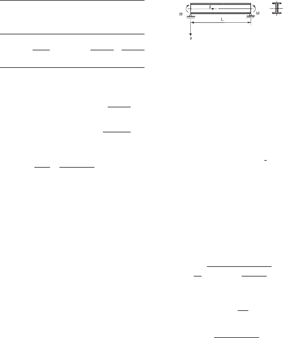
simply supported, locally stable I-beam is subject to a pure
moment M as shown in Fig. 4.23, the following differential
equations for the lateral–torsional buckling of such a beam
Figure 4.23 Simply supported beam subjected to end momens.
are given by Galambos in Ref. 2.45:
EI
y
u
iv
+ Mφ
= 0 (4.23)
EC
w
φ
1v
− GJ φ + Mu
= 0 (4.24)
where M = pure bending moment
E = modulus of elasticity
G = shear modulus, =E /2(1 + μ)
I
y
= moment of inertia about y axis
C
w
= warping constant of torsion of the cross
section (see Appendix B)
J = St. Venant torsion constant of cross section
approximately determined by
1
3
b
i
t
3
i
u = deflection of shear center in x direction
φ = angle of twist
The primes indicate differentiation with respect to z .
Considering the simply supported condition, the end
sections cannot deflect or twist; they are free to warp,
and no end moment exists about the y axis. The boundary
conditions are
u(0) = u(L) = φ(0) = φ(L) = 0 (4.25)
u
(0) = u
(L) = φ
(0) = φ
(L) = 0 (4.26)
The solution of Eqs. (4.23) and (4.24) gives the following
equation for the critical lateral buckling moment:
M
cr
=
nπ
L
EI
y
GJ
1 +
n
2
π
2
EC
w
GJ L
2
(4.27)
where L is the span length and n = 1, 2, 3, ....
The deflected shape of the beam is
φ = C sin
nπz
L
(4.28)
and the lateral deflection u can be determined by
u =
CML
2
sin(nπz/L)
n
2
π
2
EI
y
(4.29)
The deflection history of the I-beam is shown in Fig. 4.24.
When M<M
cr
and M = M
cr
but lateral–torsional buck-
ling has not yet occurred, the beam deflects in the y direc-
tion. The vertical deflection v can be obtained from Eq.
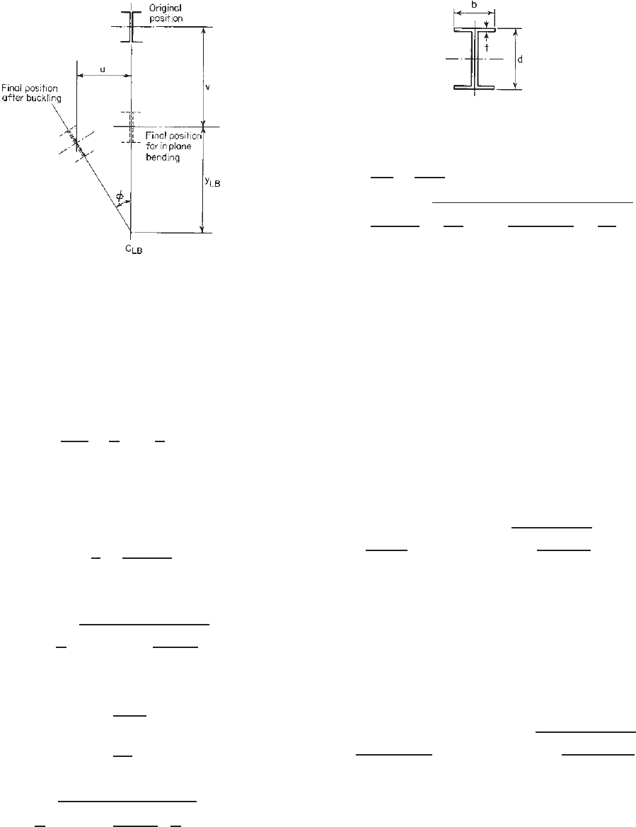
124 4 FLEXURAL MEMBERS
Figure 4.24 Positions of I-beam after lateral-torsional buckling.
(4.30) for in-plane bending,
EI
x
v
=−M (4.30)
Solving Eq. (4.30) and using the boundary conditions v(0)
= v(L) = 0, the deflection equation is
2.45
v =
ML
2
2EI
x
z
L
−
z
L
2
(4.31)
When the beam buckles laterally, the section rotates about
the center of rotation C
LB
. This point is located at a distance
of y
LB
below the shear center of the section as determined
by Eq. (4.32),
y
LB
u
φ
=
ML
2
n
2
π
2
EI
y
(4.32)
From Eq. (4.27), for n = 1, the lowest critical moment
for lateral–torsional buckling of an I-beam is equal to
M
cr
=
π
L
EI
y
GJ
1 +
π
2
EC
w
GJL
2
(4.33)
For I-beams (Fig. 4.25)
C
w
b
3
td
2
24
(4.34)
I
y
b
3
t
6
(4.35)
Equation (4.33) can then be rewritten as follows:
M
cr
=
π
L
EI
y
GJ +
E
2
I
2
y
d
2
4
π
L
2
(4.36)
Consequently the critical stress for lateral–torsional buck-
ling of an I-beam subjected to pure bending is given by
Figure 4.25 Dimensions of I-beam.
σ
cr
=
M
cr
S
x
=
M
cr
d
2I
x
=
π
2
E
2(L/d)
2
I
y
2I
x
2
+
JI
y
2(1 + μ)I
2
x
L
πd
2
(4.37)
where S
x
is the section modulus and I
x
is the moment of
inertia of the full section about the x axis. The unpublished
data of 74 tests on lateral–torsional buckling of cold-
formed steel I-sections of various shapes, spans, and loading
conditions have demonstrated that Eq. (4.37) applies to
cold-formed steel sections with reasonable accuracy.
1.161
In Eq. (4.37) the first term under the square root
represents the strength due to lateral bending rigidity
of the beam, and the second term represents the St.
Venant torsional rigidity. For thin-walled cold-formed steel
sections, the first term usually exceeds the second term
considerably.
For simply supported I-beams w ith unequal flanges, the
following equation has been derived by Winter for the
elastic lateral–torsional buckling stress
1.161,3.84,4.15
:
σ
cr
=
π
2
Ed
2L
2
S
xc
I
yc
− I
yt
+ I
y
1 +
4GJ L
2
π
2
I
y
Ed
2
(4.38)
where S
xc
is the section modulus relative to the compres-
sion fiber and I
yc
and I
yt
are the moments of inertia of the
compression and tension portions of the full section, respec-
tively, about the centroidal axis parallel to the web. Other
symbols were defined previously. For equal-flange sections,
I
yc
= I
yt
= I
y
/2 Eqs. (4.37) and (4.38) are identical.
For other than simply supported end conditions, Eq.
(4.38) can be generalized as given in Eq. (4.38a) as
follows
1.337
:
σ
cr
=
π
2
Ed
2(K
y
L
y
)
2
S
xc
I
yc
− I
yt
+ I
y
1 +
4GJ (K
t
L
t
)
2
π
2
I
y
Ed
2
(4.38a)
In the above equation, K
y
and K
t
are effective length
factors and L
y
and L
t
are unbraced lengths for bending
about the y axis and for twisting, respectively.
As previously discussed, in Eq. (4.38a) the second term
under the square root represents the St. Venant torsional