Yu W., LaBoube R.A. Cold-Formed Steel Design
Подождите немного. Документ загружается.

DESIGN EXAMPLES 235
Table 6.3 Values of ψ and C
m
5.67,1.148,3.150
C
m
Case ψ ASD LRFD and LSD
01.0 1.0
−0.4 1 − 0.4
c
P
P
E
1 − 0.4
P
P
E
−0.4 1 − 0.4
c
P
P
E
1 − 0.4
P
P
E
−0.2 1 − 0.2
c
P
P
E
1 − 0.2
P
P
E
−0.3 1 − 0.3
c
P
P
E
1 − 0.3
P
P
E
−0.2 1 − 0.2
c
P
P
E
1 − 0.2
P
P
E
value of C
m
can be computed by using the following
equations
5.67,6.6
:
C
m
=
⎧
⎪
⎪
⎪
⎨
⎪
⎪
⎪
⎩
1 + ψ
c
P
P
E
(ASD) (6.66a)
1 + ψ
P
P
E
(LRED and LSD) (6.66b)
where ψ = (π
2
δEI/M
0
L
2
) − 1
δ = maximum deflection due to transverse loading
M
0
= maximum moment between supports due to
transverse loading
P
E
= P
Ex
or P
Ey
, whichever is applicable
Values o f ψ are given in Ta ble 6.3 for various loading
conditions and end restraints.
5.67,1.148,3.150
6.5 DESIGN EXAMPLES
Example 6.1 Check the adequacy of the tubular section
described in Example 5.1 if it is used as a beam–column
to carry an axial load of 30 kips and end moments of
60 in.-kips (Fig. 6.8). The yield stress of steel is 40 ksi. The
unbraced length is 10 ft and K
x
= K
y
= 1.0. The member
is assumed to be bent in single curvature. Use the ASD
and LRFD methods. Assume that the dead load–live load
ratio is
1
5
.
SOLUTION
A. ASD Method
1. Sectional Properties of Full Section. From Example
5.1, the sectional properties of the full section are as
Figure 6.8 Example 6.1.
follows:
A = 3.273 in.
2
I
x
= I
y
= 33.763 in.
4
r
x
= r
y
= 3.212 in.
2. Applied Axial Load and Moments
P = 30 kips
M
x
= 60 in.-kips
M
y
= 0
3. Selection of Design Equations. Based on the design
procedure discussed in C hapter 5, the nominal axial strength
was computed in Example 5.1 as
P
n
= 78.738 kips
c
P
P
n
=
1.80(30)
78.738
= 0.686 > 0.15
Use Eqs. (6.53) and (6.54) to check the adequacy of the
tubular section.
236 6 COMBINED AXIAL LOAD AND BENDING
4. Application of Eqs. (6.53 ) and (6.54 ). Equation (6.53)
is used to check the beam–column for the stability require-
ment between braced points.
a. Computation of M
nx
. The nominal flexural strength
about the x axis should be determined according to
Section 4.2. C onsideration should be given to section
strength and lateral–torsional buckling strength.
i. Section Strength. According to Section 4.2.2, the
nominal moment M
n
can be computed on the basis
of the initiation of yielding (Procedure I of the AISI
specification) as follows:
R
= R +
t
2
= 0.240 in. (corner element)
L = 1.57R
= 0.377 in. (arc length)
c = 0.637R
= 0.153 in.
Location of neutral axis and computation of I
x
and
S
x
. For the stiffened compression flange,
w = 8 − 2
(
R + t
)
= 8 − 2(0.1875 + 0.105)
= 7.415 in.
w
t
=
7.415
0.105
= 70.619 < 500 OK
λ =
1.052
√
k
w
t
!
f
E
=
1.052
√
4.0
(
70.619
)
40
29,500
= 1.368 > 0.673
ρ = 1 −
0.22/λ
λ
= 1 −
0.22/1.368
1.368
= 0.613
b = ρw =
(
0.613
)(
7.415
)
= 4.545 in.
By using the effective width of the compression
flange and assuming the web is fully effective, the
neutral axis can be located as follows:
Distance from Top
Element Effective Length L (in.) Fiber y (in.) Ly (in.
2
) Ly (in.
3
)
Compression flange 4.545 0.0525 0.239 0.013
Compression corners 2 × 0.377 = 0.754 0.1395 0.105 0.013
Webs 2 × 7.415 = 14.830 4.0000 59.320 237.280
Tension corners 2 × 0.377 = 0.754 7.8605 5.927 46.588
Tension flange
7.415 7.9475 58.931 468.352
28.298 124.522 752.248
y
cg
=
124.522
28.298
= 4.400 in. >
d
2
=
8
2
= 4.000 in.
The maximum stress of 40 ksi occurs in the
compression flange as summed in the calculation.
Check the effectiveness of the web. Use Section
3.5.1.2 to check the effectiveness of the web element.
From Fig. 6.9,
f
1
= 40
4.1075
4.400
= 37.341 ksi
(
compression
)
f
2
= 40
3.3075
4.400
= 30.068 ksi
(
tension
)
ψ =
"
"
"
"
f
2
f
1
"
"
"
"
=
30.068
37.341
= 0.805
k = 4 + 2
(
1 + ψ
)
3
+ 2
(
1 + ψ
)
= 4 +2(1 + 0.805)
3
+ 2(1 + 0.805)
= 19.371
h
t
=
7.415
0.105
= 70.619 < 200 OK
λ =
1.052
√
19.371
(
70.619
)
37.341
29,500
= 0.601 < 0.673
b
e
= h = 7.415 in.
Because h
0
/b
0
= 8.00/8.00 = 1 < 4andψ>
0.236, Eqs. (3.55a) and (3.55b) are used to compute
b
1
and b
2
:
b
1
=
b
e
3 + ψ
= 1.949 in.
b
2
=
1
2
b
e
= 3.708 in.
b
1
+ b
2
= 5.657 in.
Because the computed value of b
1
+ b
2
is greater
than the compression portion of the web (4.1075 in.),
DESIGN EXAMPLES 237
Figure 6.9 Stress distribution in webs using fully effective webs.
the web is fully effective. The moment of inertia
based on line element is
2I
web
= 2
1
12
(
7.415
)
3
= 67.949
#
Ly
2
= 752.248
I
z
= 820.197 in.
3
−
(
L
)
y
cg
2
=−
(
28.298
)(
4.40
)
2
=−547.849 in.
3
I
x
= 272.348 in.
3
The actual moment of inertia is
I
x
= I
x
(
t
)
=
(
272.348
)(
0.105
)
= 28.597 in.
4
The section modulus relative to the extreme
compression fiber is
S
ex
=
28.597
4.40
= 6.499 in.
3
The nominal moment for section strength is
M
nx
= S
ex
F
y
= (6.499)(40) = 259.960 in.-kips
ii. Lateral–torsional Buckling Strength. Because the
tubular member is a closed box section, the
lateral–torsional buckling strength of the member
can be checked by using Section 4.2.3.4 in this
volume on Section C 3.1.2.2 of the 2007 edition
of the North American specification. According to
Eq. (4.78),
L
u
=
0.36C
b
π
F
y
S
f
EI
y
GJ
in which
C
b
= 1.0 for combined axial load and bending
J =
2b
2
d
2
t
b + d
=
2
(
8 − 0.105
)
4
(
0.105
)
2
(
8 − 0.105
)
=51.67 in.
4
S
f
=
1
4
× 33.763 = 8.44 in.
3
Therefore
L
u
=
0.36
(
1
)
π
40 × 8.44
×
(
29,500
)(
33.763
)(
11,300
)(
51.67
)
= 2,554.7in.
Since the unbraced length of 120 in. is less than L
u
,
lateral–torsional buckling will not govern the design.
iii. Nominal Moment M
nx
. From the above calculations,
M
nx
= 259.960 in.-kips.
b. Computation of C
mx
. Using Eq. (6.60),
C
mx
= 0.6 − 0.4
M
1
M
2
= 0.6 − 0.4
−
60
60
= 1.0
c. Computation of α
x
. Using Eq. (6.56),
α
x
= 1 −
c
P
P
Ex
where
P
Ex
=
π
2
EI
x
(
K
x
L
x
)
2
=
π
2
(
29,500
)(
33.763
)
(
1 × 10 ×12
)
2
= 682.653 kips
α
x
= 1 −
1.80(30)
682.653
= 0.921 > 0OK
d. Check Eq. (6.53 ). Substituting the above computed
values into Eq. (6.53),
c
P
P
n
+
b
C
mx
M
x
M
nx
α
x
=
(
180
)(
30
)
78.738
+
(
1.67
)(
1
)(
60
)
(
259.96
)(
0.921
)
= 1.104 > 1.0
(
no good
)
5. Application of Eq. (6.54 ). Equation (6.54) is used to
check the beam–column for the yielding requirement at
braced points.
238 6 COMBINED AXIAL LOAD AND BENDING
a. Computation of P
no
. The nominal axial strength P
no
is
computed for KL/r = 0(i.e.,F
n
= F
y
= 40 ksi). For
stiffened compression elements,
λ =
1.052
√
4.0
(
70.619
)
40
29,500
= 1.368 > 0.673
ρ = 1 −
0.22/1.368
1.368
= 0.613
b = ρw =
(
0.613
)(
7.415
)
= 4.545 in.
A
e
= 3.273 − 4(7.415 − 4.545)
(
0.105
)
= 2.068 in.
2
P
no
= A
e
F
n
= (2.068)(40) = 82.720 kips
b. Check Eq. (6.54).
c
P
P
no
+
b
M
x
M
nx
=
(
1.80
)(
30
)
82.720
+
(
1.67
)(
60
)
259.96
= 1.038 > 1.0
(
no good
)
Based on the above calculations for the ASD method, it
can be seen that the given tubular member is inadequate
for the applied load and end moments.
B. LRFD Method
1. Applied Axial Load and Moments. From the given
data,
P
D
= 5kips
P
L
= 25 kips
M
D
= 10 in.-kips
M
L
= 50 in.-kips
2. Required Strengths. Based on the load factors and
load combinations discussed in Section 3.3.2.2, the
required strengths P
u
and M
ux
can be computed as
follows: From Eq. (3.5a),
(P
u
) = 1.4P
D
= 1.4(5) = 7kips
(M
ux
)
1
= 1.4M
D
= 1.4(10) = 14 in.-kips
From Eq. (3.5b),
(P
u
)
2
= 1.2P
D
+ 1.6P
L
= 1.2(5) + 1.6(25)
= 46 kips
(M
ux
)
2
= 1.2M
D
+ 1.6M
L
= 1.2(10) + 1.6(50)
= 92 in.-kips
Use P
u
= 46 kips and M
ux
= 92 in.-kips
3. Nominal Axial Strength and Nominal Flexural
Strength. From Example 5.1 and the above
calculations for the ASD method,
P
n
= 78.738 kips
P
no
= 82.720 kips
P
Ex
= 682.653 kips
M
nx
= 259.960 in.-kips
4. Selection of Design Equations. Since P
u
/φ
c
P
n
=
46/(0.85 × 78.738) = 0.687 > 0.15, use Eqs. (6.61)
and (6.62) to check the adequacy of the tubular
section.
5. Application of Eq. (6.61 ). Since the values of
P
u
,P
n
,P
no
,P
Ex
,M
ux
,M
nx
,φ
c
,andφ
b
are known,
calculations are needed only for C
mx
and α
x
as
follows: From Eq. (6.60),
C
mx
= 0.6 − 0.4
M
1
M
2
= 0.6 − 0.4
−
92
92
= 1.0
Based on Eq. (6.64),
α
x
= 1 −
P
u
P
Ex
= 1 −
46
682.653
= 0.933 > 0OK
Using Eq. (6.61),
P
u
φ
c
P
n
+
C
mx
M
ux
φ
b
M
nx
α
x
=
46
(
0.85
)(
78.738
)
+
(
1
)(
92
)
(
0.95
)(
259.96
)(
0.933
)
= 1.087 > 1.0
(
no good
)
6. Application of Eq. (6.62 ). Based on Eq. (6.62),
P
u
φ
c
P
no
+
M
ux
φ
b
M
nx
=
46
(
0.85
)(
82.720
)
+
92
(
0.95
)(
259.96
)
= 1.027 > 1.0
(
no good
)
According to the above calculations for the LRFD
method, the given tubular member is also inadequate for
the applied load and moments. The difference between the
ASD and LRFD methods is less than 1.5%.
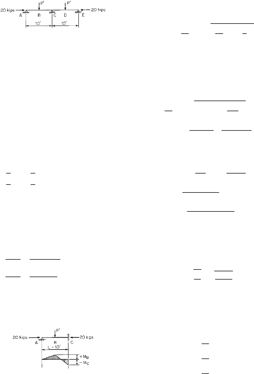
Example 6.2 IftheI-sectionusedinExample5.2isto
be used as a beam–column as shown in Fig. 6.10, what
is the maximum allowable transverse load P
applied at
the midspan length? Assume that the axial load is 20 kips
and the beam is laterally supported at A, B, C, D, and E.
Use F
y
= 33 ksi and the ASD method. The intermediate
fastener spacing is assumed to be 12 in.
DESIGN EXAMPLES 239
Figure 6.10 Example 6.2.
SOLUTION
1. Sectional Properties of Full Section. From Example
5.2, the sectional properties of the I-section are
as follows:
A = 2.24 in.
2
J = 0.00418 in.
4
I
x
= 22.1in.
4
C
w
= 70.70 in.
6
S
x
= 5.53 in.
3
r
0
= 3.435 in.
I
y
= 4.20 in.
4
r
x
= 3.15 in.
S
y
= 1.40 in.
3
r
y
= 1.37 in.
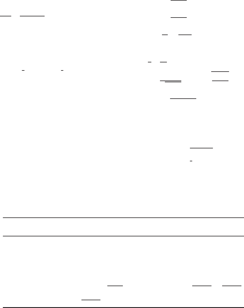
2. Applied Axial Load and Moments. Since the contin-
uous beam is subject to symmetric loads P
in two equal
spans, the moment diagram can be drawn as shown in
Fig. 6.11. The positive and negative moments are
+M
B
=
5
32
P
L =
5
32
P
(10)(12) = 18.75P
in.-kips
−M
C
=
3
16
P
L =
3
16
P
(10)(12) = 22.5P
in.-kips
As given in the problem, the applied axial load is
P = 20 kips
3. Computation of P
n
a. Nominal Buckling Stress F
n
i. Elastic Flexural Buckling. By using Eq. (5.56), the
elastic flexural buckling stress can be computed as
follows:
K
x
L
x
r
x
=
1 × 10 ×12
3.15
= 38.10
K
y
L
y
r
y
=
1 × 5 ×12
1.37
= 43.80 < 200 OK
Since the slenderness ratio (KL/r = K
y
L
y
/r
y
)is
governed by the column buckling about the y axis of
the I-section, which involves relative deformations
that produce shear forces in the connections
Figure 6.11 Moment diagram for the continuous beam.
between individual channels, the modified slender
ratio (KL/r)
m
should be used to compute the elastic
flexural stress F
e.
Based on Eq. (5.76),
KL
r
m
=
KL
r
2
0
+
a
r
i
2
where (KL/r)
0
= 43.80
a = intermediate fastener spacing,
=12 in.
r
i
= radius of gyration of a channel
section about its y axis, =1.08 in.
Therefore,
KL
r
m
=
(
43.80
)
2
+
12
1.08
2
= 45.19
F
e
=
π
2
E
(
KL/r
)
2
m
=
π
2
(
29,500
)
(
45.19
)
2
=142.57 ksi
ii. Elastic Torsional Buckling. From Eq. (5.22)
or Section C3.1.2.1(a) of the North American
specification, the torsional buckling stress is
F
e
= σ
t
=
1
Ar
2
0
GJ +
π
2
EC
w
(
K
t
L
t
)
2
=
1
(2.24)(3.435)
2
(11,300)(0.00418)
+
π
2
(29,500)(70.70)
(5 × 12)
2
= 218.13 ksi
The nominal buckling stress F
n
is determined
by using the smaller value of the elastic flexural
buckling stress and torsional buckling stress, that is,
F
e
= 142.57 ksi
λ
c
=
F
y
F
e
=
33
142.57
= 0.481 < 1.5
From Eq. (5.54),
F
n
=
0.658
λ
2
c
!
F
y
=
0.658
0.481
2
!
(33) = 29.95 ksi
b. Effective Area A
e
at Stress F
n
. From Example 5.2, the
flat widths of the edge stiffener, flange, and web are
w
1
= 0.5313 in.
w
1
t
= 7.084
w
2
= 2.6625 in.
w
2
t
= 35.50 < 60 OK
w
3
= 7.6625 in.
w
3
t
= 102.167 < 500 OK

240 6 COMBINED AXIAL LOAD AND BENDING
i. Effective Width of Compression flange. From Eq.
(3.80),
S = 1.28
E
f
= 1.28
29,500
29.95
= 40.17
0.328S = 13.18
w
2
t
= 35.50
Since w
2
/t > 0.328S, use Eq. (3.81) to compute the
adequate moment of inertia of the edge stiffener I
a
as follows:
I
a
= 399t
4
[
(
w
2
/
t
)
/
S − 0.328
]
3
= 399
(
0.075
)
4
[
35.50
/
40.17 − 0.328
]
3
= 0.0022 in.
4
The above computed value should not exceed the
following value:
I
a
= t
4
[
115
(
w
2
/
t
)
/
S + 5
]
=
(
0.075
)
4
[
115
(
35.50
)
/
40.17 + 5
]
= 0.0034 in.
4
Therefore, use I
a
= 0.0022 in.
4
For the simple lip edge stiffener,
D = 0.7in.
d = 0.5313 in.
d
t
=
0.5313
0.075
= 7.084
By using Eq. (3.83), the moment of inertia of the
full edge stiffener is
I
s
=
1
12
d
3
t =
1
12
(0.5313)
3
(0.075) =0.000937 in.
4
From Eq. (3.82),
R
I
=
I
s
I
a
=
0.000937
0.0022
= 0.426 < 1.0OK
The effective width b of the compression flange can
be computed as follows:
D
w
2
=
0.7
2.6625
= 0.263
From Eq. (3.84),
n =
[
0.582 −
(
w
2
/
t
)
/
4S
]
=
[
0.582 −
(
35.50
)
/
(
4 × 40.17
)
]
= 0.361 >
1
3
,
use n = 0.361
Since 0.25 <D/w
2
< 0.8, and θ = 90
◦
,
k = [4.82 − 5D/w
2
](R
I
)
n
+ 0.43
= [4.82 − 5(0.263)](0.426)
0.361
+ 0.43
= 2.576 < 4.0
Use k = 2.576 to compute the effective width of the
compression flange. From Eqs. (3.41)–(3.44),
λ =
1.052
√
2.576
(
35.50
)
29.95
29,500
= 0.741 > 0.673
ρ = 1 −
0.22/λ
λ
= 1 −
0.22/0.741
0.741
= 0.949
b = ρw
2
=
(
0.949
)(
2.6625
)
= 2.527 in.
ii. Effective Width of Edge Stiffeners
w
1
t
= 7.084
λ =
1.052
√
0.43
(
7.084
)
29.95
29,500
= 0.362 < 0.673
d
s
= w
1
= 0.5313 in.
Based on Eq. (3.79), the reduced effective width of
the edge stiffener is
d
s
= R
I
d
s
=
(
0.426
)(
0.5313
)
= 0.226 <d
s
OK
iii. Effective Width of Web Elements
w
3
t
= 102.167
λ =
1.052
√
4.0
(
102.167
)
29.95
29,500
= 1.712 > 0.673
ρ = 1 −
0.22/1.712
1.712
= 0.509
b = ρw
3
=
(
0.509
)(
7.6625
)
= 3.900 in.
iv. Effective Area A
e
A
e
= 2.24 − [4(0.5313 − 0.226)
+ 4(2.6625 − 2.527)
+ 2(7.6625 − 3.900)](0.075)
= 1.543 in.
2
c. Nominal Load Based on Flexural Buckling P
n
P
n
= A
e
F
n
= (1.543)(29.95) = 46.21 kips
4. Nominal Load Based on Distortional Buckling.
According to Section C4.2(b) of the North American
specification, Example 5.2 shows that the nominal
axial load for distortional buckling based on L
m
= L
y
= 72 in. is P
n
= 49.25 kips. For this example, L
m
= L
y
= 60 in., which is also greater than L
cr
= 25.35 in.
DESIGN EXAMPLES 241
computed from Example 5.2. The same nominal axial
load for distortional buckling can also be used for this
case.
Since the nominal axial load for flexural buckling calcu-
lated in item 3 above is smaller than the nominal load for
distortional buckling, flexural buckling controls. Therefore,
the design should use P
n
= 46.21 kips.
5. Selection of Design Equations
c
P
P
n
=
(1.80)(20)
46.21
= 0.779 > 0.15
Use Eqs. (6.53) and (6.54).
6. Application of Eq. (6.53)
a. Computation of M
nx
i. Section Strength Based on Initiation of Yielding
(Section 4.2.2.1). For the corner element,
R
= R +
1
2
t = 0.09375 +
1
2
× 0.075 = 0.1313 in.
The arc length is
L = 1.57R
= 0.206 in.
c = 0.637R
= 0.0836 in.
For the compression flange, the effective width for
f = F
y
= 33 ksi is b = 2.430 in. For the compres-
sion edge stiffener, the compression stress is conser-
vatively assumed to be f = F
y
= 33 ksi. Following
the same procedure used in item 3.b, the effective
length of the edge stiffener at a stress of 33 ksi is
0.184 in. See item A.1.iii of Example 4.2 for using
Section 3.5.2.2 to determine the reduced effective
width of the edge stiffener. By using the effective
widths of the compression flange and edge stiffener
and assuming the web is fully effective, the neutral
axis can be located as follows:
Distance from Top
Element Effective Length L (in.) Fiber y(in.) Ly (in.
2
) Ly
2
(in.
3
)
Compression flange 2 × 2.430 = 4.860 0.0375 0.182 0.007
Compression corners 4 × 0.206 = 0.824 0.0852 0.070 0.006
Compression stiffeners 2 × 0.184 = 0.368 0.2608 0.096 0.025
Webs 2 × 7.6625 = 15.325 4.0000 61.300 245.200
Tension stiffeners 2 × 0.5313 = 1.063 7.5656 8.042 60.843
Tension corners 4 × 0.206 = 0.824 7.9148 6.522 51.620
Tension flange 2 × 2.6625 =
5.325 7.9625 42.400 337.610
28.589 118.612 695.311
y
cg
=
118.612
28.589
= 4.149 in.
Since y
cg
>d/2 = 4.000 in., the maximum stress
of 33 ksi occurs in the compression flange as
assumed in the above calculation.
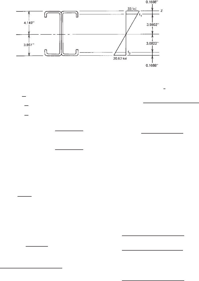
The effectiveness of the web is checked according
to Section 3.5.1.2.
From Fig. 6.12,
f
1
= 33
3.9802
4.149
= 31.66 ksi (compression)
f
2
= 33
3.6822
4.149
= 29.29 ksi (tension)
ψ =
"
"
"
"
f
2
f
1
"
"
"
"
=
29.29
31.66
= 0.925
k = 4 + 2
(
1 + 0.925
)
3
+ 2
(
1 + 0.925
)
= 22.116
h
t
=
w
3
t
= 102.167
λ =
1.052
√
22.116
(
102.167
)
31.66
29,500
=0.749 > 0.673
ρ = 1 −
0.22/0.749
0.749
= 0.943
b
e
= 0.943
(
7.6625
)
= 7.229 in.
Because h
0
/b
0
= 8.00/3.00 = 2.67 < 4and
ψ>0.236, Eqs. (3.55a) and (3.55b) are used to
compute b
1
and b
2
:
b
1
=
7.229
3 + 0.925
= 1.842 in.
b
2
=
1
2
× 7.229 = 3.614 in.
b
1
+ b
2
= 1.842 + 3.614 = 5.456 in.
Because the computed value of b
1
+ b
2
is greater
than the compression portion of the web (3.9802 in.),
the web is fully effective.
242 6 COMBINED AXIAL LOAD AND BENDING
Figure 6.12 Stress distribution in webs.
The moment of inertia based on line elements is
2I
web
= 2
1
12
(
7.6625
)
3
= 74.983
2I
comp.stiffener
= 2
1
12
(
0.184
)
3
= 0.001
2I
tension stiffener
= 2
1
12
(
0.531
)
3
= 0.025
#
(Ly
2
) = 695.311
I
z
= 770.320 in.
3
−(L)
y
cg
2
=−(28.589)
(
4.149
)
2
=−492.137
I
x
= 278.183 in.
3
The actual moment of inertia is
I
x
= I
x
(t) =
(
278.183
)(
0.075
)
= 20.864 in.
4
The section modulus relative to the extreme
compression fiber is
S
ex
=
20.864
4.149
= 5.029 in.
3
The nominal moment for section strength is
M
nx
= S
ex
F
y
= (5.029)(33) = 165.96 in.-kips
ii. Lateral–Torsional Buckling Strength. For segment
AB, K
y
L
y
= 5 ft. According to Eq. (4.73a),
F
e
=
π
2
EC
b
dl
yc
S
f
(K
y
L
y
)
2
In the above equation,
C
b
=
12.5M
max
2.5M
max
+ 3M
1
+ 4M
2
+ 3M
3
where M
max
= M
B
at point B
M
1
= 0.25M
B
at
1
/
4
pint of unbraced
segment
M
2
= 0.50M
B
at midspan of unbraced
segment
M
3
= 0.75M
B
at
3
4
point of unbraced
segment
C
b
=
12.5(M
B
)
2.5(M
B
) + 3(0.25M
B
)
+4(0.50M
B
) + 3(0.75M
B
)
= 1.67
Therefore, F
e
=
π
2
(
29,500
)(
1.67
)(
8
)(
4.20/2
)
(
5.53
)(
5×12
)
2
= 410.32 ksi
0.56F
y
= 18.48 ksi
2.78F
y
= 91.74 ksi
Since F
e
> 2.78F
y
,F
c
= F
y
= 33 ksi.
Because the elastic section modulus of the effec-
tive section calculated at a stress of F
c
= 33 ksi
in the extreme compression fiber is S
c
= S
ex
=
5.029 in.
3
, the nominal moment for lateral–torsional
buckling is
M
nx
= S
c
F
c
= (5.029)(33) = 165.96 in.-kips
For segment BC, K
y
L
y
= 5ft, M
B
= 18.75 P
and M
c
= 22.5 P
in.-kips. The value of C
b
is
C
b
=
12.5M
max
2.5M
max
+ 3M
1
+ 4M
2
+ 3M
3
=
12.5(22.5P
)
2.5(22.5P
) + 3(8.4375P
)
+4(1.875P
) + 3(12.1875P
)
= 2.24
F
e
=
π
2
(
29,500
)(
2.24
)(
8
)(
4.20/2
)
(
5.53
)(
5 × 12
)
2
= 550.37 ksi
Since F
e
> 2.78F
y
,F
c
= F
y
= 33 ksi,
M
nx
= S
c
F
c
= 165.96 in.-kips
DESIGN EXAMPLES 243
Based on the section strength and lateral–torsional
buckling strength,
M
nx
= 165.96 in.-kips
iii. Distortional Buckling Strength. The nominal moment
for distortional buckling can be computed according
to Section C3.1.4(b) of the North American Speci-
fication. Following the procedure illustrated in item
B of Example 4.13 and using Eqs. (4.115)–(4.119),
the computed rotational stiffnesses are as follows:
k
φfe
= 0.534 in.-kips/in.
k
φwe
= 0.482 in.-kips/in.
k
φ
= 0
$
k
φfg
= 0.0203 (in.-kips/in.)/ksi
$
k
φwg
= 0.00205 (in.-kips/in.)/ksi
Use a conservative value of β = 1.0 in. Eq. (4.113),
F
d
= (1.0)
0.534 + 0.482 + 0
0.0203 + 0.00205
= 45.46 ksi
From Eqs. (4.105)–(4.108),
M
crd
= S
f
F
d
= (5.53)(45.46) = 251.39 in.-kips
M
y
= S
fy
F
y
= (5.53)(33) = 182.49 in.-kips
λ
d
=
M
y
M
crd
=
182.49
251.39
= 0.852 > 0.673
M
n
= [1 − 0.22(M
crd
/M
y
)
0.5
](M
crd
/M
y
)
0.5
M
y
=
1 − 0.22
251.39
182.49
0.5
251.39
182.49
0.5
× (182.49)
= 158.88 in.-kips
Since the above computed distortional buckling
strength is smaller than the section strength and
lateral–torsional buckling strength, use
M
nx
= 158.88 in.-kips
b. Computation of C
mx
. Based on case 3 of the definition
of C
mx
,use
C
mx
= 1.0
c. Computation of α
x
. Using Eq. (6.56),
α
x
= 1 −
c
P
P
Ex
where
P
Ex
=
π
2
EI
x
(
K
x
L
x
)
=
π
2
(
29,500
)(
22.1
)
(
1 × 10 ×12
)
2
= 446.84 kips
Therefore,
α
x
= 1 −
1.80(20)
446.84
= 0.919
d. Allowable Load P
BasedonEq.(6.53 ). Using
Eq. (6.53),
c
P
P
n
+
b
C
mx
M
x
M
nx
α
x
=
(
1.80
)
20
46.21
+
(
1.67
)(
1
)
22.5P
(
158.88
)(
0.919
)
= 1.0
P
= 0.859 kips
7. Application of Eq. (6.54)
a. Computation of P
n0
.ForKL/r = 0, F
n
= F
y
= 33 ksi.
Using the same procedure illustrated in item 3,
A
e
(for F
y
= 33 ksi) = 1.507 in.
2
P
n0
= A
e
F
n
= 49.73 kips
b. Allowable Load P
Based on Eq. (6.54 )
c
P
P
no
+
b
M
x
M
nx
=
(
1.80
)
20
49.73
+
(
1.67
)
22.5P
158.88
= 1.0
P
= 1.167 kips
8. Allowable Load P
. Based on Eqs. (6.53) and (6.54),
the allowable load for the ASD method is 0.859 kips, which
is governed by the stability requirement. For the LRFD
method, Eqs. (6.61) and (6.62) should be used with the
load factors a nd combinations given in Section 3.3.2.2.
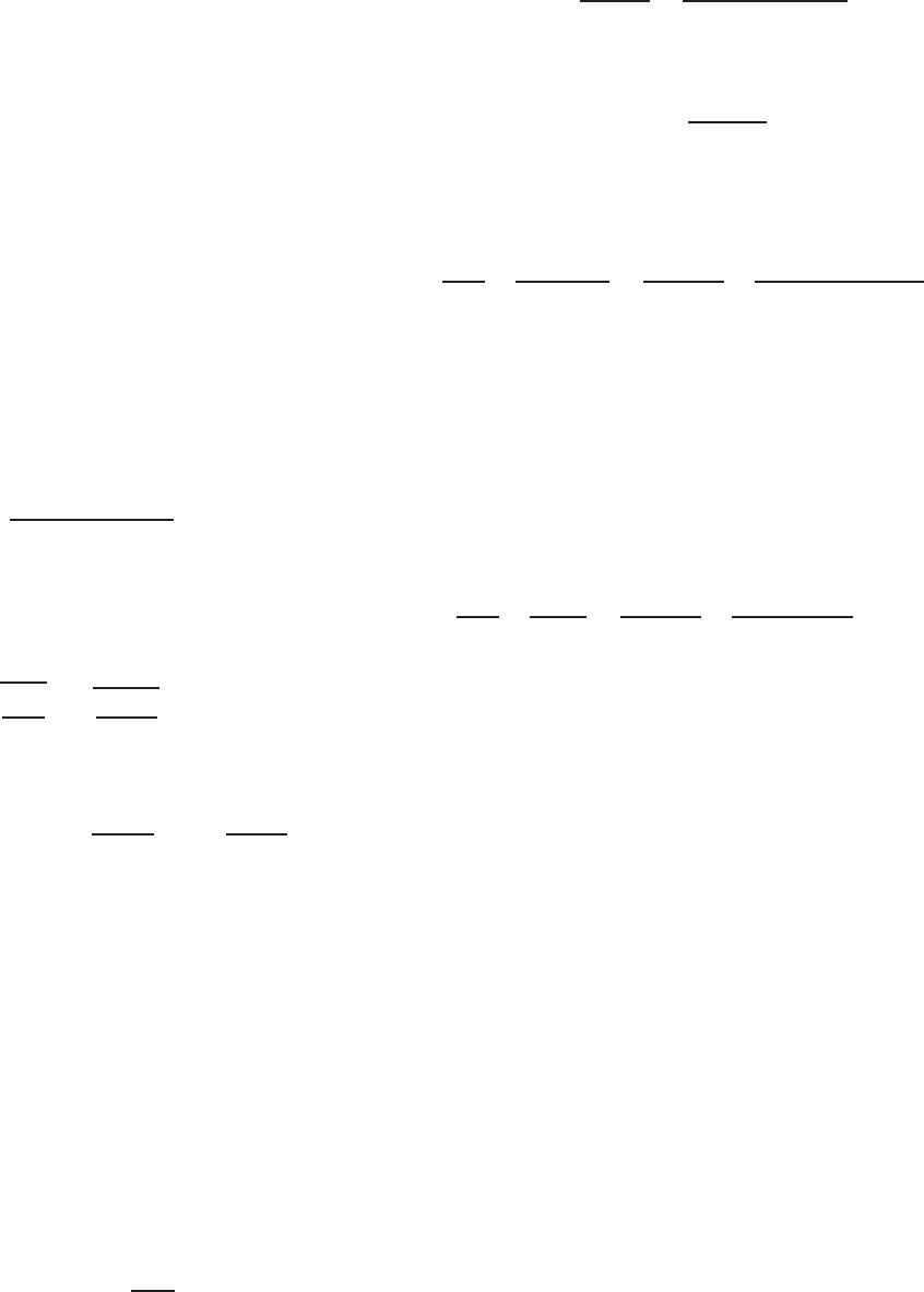
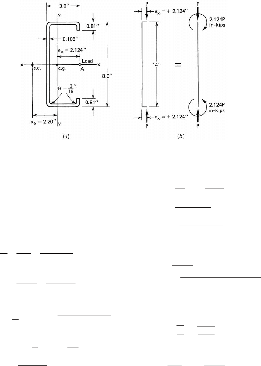
Example 6.3 For the braced channel c olumn shown in
Fig. 6.13, determine the allowable load if the load at
both ends are eccentrically applied at point A (that is,
e
x
=+2.124 in.) along the x axis (Fig. 6.13a). Assume
K
x
L
x
= K
y
L
y
= K
z
L
z
= 14 ft. Use F
y
= 50 ksi and the
ASD method.
SOLUTION
1. Properties of Full Section. From the equations given
in Part I of the AISI Design Manual,
1.349
the following full
section properties can be computed:
A = 1.553 in.
2
x = 0.876 in.
I
x
= 15.125 in.
4
J = 0.0571 in.
4
S
x
= 3.781 in.
3
C
w
= 24.1in.
6
r
x
= 3.12 in. j = β
y
/2 = 4.56 in.
I
y
= 1.794 in.
4
r
0
= 3.97 in.
S
y
= 0.844 in.
3
x
0
= 2.20 in.
r
y
= 1.075 in.
244 6 COMBINED AXIAL LOAD AND BENDING
Figure 6.13 Example 6.3.
2. Applied Axial Load and End Moments
P = axial load to be determined
M
x
= 0
M
y
= 2.124P in.-kips
3. Computation of P
n
BasedonFlexuraland
Flexural–Torsional Buckling
a. Nominal Buckling Stress F
n
i. Elastic Flexural Buckling Stress. Since K
x
L
x
=
K
y
L
y
and r
x
>r
y
,
KL
r
=
K
y
L
y
r
y
=
(
1
)(
14 × 12
)
1.075
= 156.28 < 200 OK
F
e
=
π
2
E
(
KL/r
)
2
=
π
2
(
29,500
)
(
156.28
)
2
= 11.921 ksi
ii. Elastic Flexural–Torsional Buckling Stress.
According to Eq. (5.57),
F
e
=
1
2β
[(σ
ex
+ σ
t
) −
(σ
ex
+ σ
t
)
2
− 4βσ
ex
σ
t
where
β = 1 −
x
0
r
0
2
= 1 −
2.20
3.97
2
= 0.693
σ
ex
=
π
2
E
(
K
x
L
x
/r
x
)
2
=
π
2
(
29,500
)
(
1 × 14 ×12/3.12
)
2
= 100.418 ksi
σ
t
=
1
Ar
2
0
GJ +
π
2
EC
w
(
K
t
L
t
)
2
=
1
(1.553)(3.97)
2
(11,300)(0.0571)
+
π
2
(29,500)(24.1)
(1 × 14 ×12)
2
= 12.793 ksi.
Therefore
F
e
=
1
2(0.693)
(100.418 + 12.793)
−
(100.418 + 12.793)
2
− 4(0.693)
×(100.418)(12.793)
⎤
⎦
= 12.269 > 11.921 ksi
Use F
e
= 11.921 ksi to compute F
n
:
λ
c
=
F
y
F
e
=
50
11.921
= 2.048 > 1.5
From Eq. (5.55),
F
n
=
0.877
λ
2
c
F
y
=
0.877
(
2.048
)
2
(
50
)
= 10.455 ksi