Yu W., LaBoube R.A. Cold-Formed Steel Design
Подождите немного. Документ загружается.

DESIGN EXAMPLES 215
According to Eq. (5.72), the critical unbraced length of
distortional buckling, L
cr
, can be computed as follows:
L
cr
=
6π
4
h
0
(1 − μ
2
)
t
3
I
xf
(x
0f
− h
x
)
2
+ C
wf
−
I
2
xyf
I
yf
(x
0f
− h
x
)
2
1/4
=
6π
4
(8.000)(1 − 0.3
2
)
(0.075)
3
0.00637
× (1.192 − (−1.733))
2
+ 0 −
(0.0196)
2
0.243
× (1.192 − (−1.733))
2
1/4
= 25.35 in.
Since (L
m
= L
y
= 72 in.)>L
cr
,useL = 25.35 in. The
elastic rotational stiffness provided by the flange to the
flange/web juncture, k
φfe
, can be computed from Eq.
(4.116) as follows:
k
φfe
=
π
L
4
EI
xf
(x
0f
− h
x
)
2
+ EC
wf
− E
I
2
xyf
I
yf
(x
0f
− h
x
)
2
+
π
L
2
GJ
f
=
π
25.35
4
(29,500)(0.00637)[1.192
− (−1.733)]
2
+ (29,500)(0.0)
−(29,500)
(0.0196)
2
0.243
[1.192 − (−1.733)]
2
+
π
25.35
2
(11,300)(0.000504)
= 0.373 in.-kips/in.
From Eq. (5.70), the elastic rotational stiffness provided
by the web to the flange/web juncture, k
φwe
,is
k
φwe
=
Et
3
6h
0
(1 − μ
2
)
=
(29,500)(0.075)
3
6(8.00)(1 − (0.3)
2
)
= 0.285 in.-kips/in.
Since no sheathing is attached to the I-section, k
φ
= 0.
From Eq. (4.118), the geometric rotational stiffness
demanded by the flange from the flange/web juncture,
˜
k
φfg
,is
˜
k
φfg
=
π
L
2
A
f
(x
0f
− h
x
)
2
I
xyf
I
yf
2
− 2y
0f
(x
0f
− h
x
)
×
I
xyf
I
yf
+ h
2
x
+ y
2
0f
+ I
xf
+ I
yf
=
π
25.35
2
(0.269)
[1.192 − (−1.733)]
2
×
0.0196
0.243
2
− 2(−0.0612)[1.192 − (−1.733)]
×
0.0196
0.243
+ (−1.733)
2
+ (−0.0612)
2
+ 0.00637 + 0.243
= 0.0166 (in.-kips/in.)/ksi
From Eq. (5.71), the geometric rotational stiffness
demanded by the web from the flange/web juncture,
˜
k
φwg
,is
˜
k
φwg
=
π
L
2
th
3
0
60
=
π
25.35
2
(0.075)(8.00)
3
60
= 0.00983 (in.-kips/in.)/ksi
From Eq. (5.69), the elastic distortional buckling stress
F
d
is
F
d
=
k
φfe
+ k
φwe
+ k
φ
˜
k
φfg
+
˜
k
φwg
=
0.373 + 0.285 +0.0
0.0166 + 0.00983
= 24.90 ksi
The distortional buckling load is
P
crd
= A
g
F
d
= (2.24)(24.90) = 55.78 kips
Based on Eq. (5.62),
λ
d
=
P
y
P
crd
=
73.92
55.78
= 1.151 > 0.561
From Eq. (5.61), the nominal axial load for distor-
tional buckling based on Section C4.2(b) of the
216 5 COMPRESSION MEMBERS
specification is
P
n
=
1 − 0.25
P
crd
P
y
0.6
P
crd
P
y
0.6
P
y
=
1 − 0.25
55.78
73.92
0.6
55.78
73.92
0.6
(73.92)
= 49.25 kips > 31.09 kips
from Part I based on Section C4.2(a) of the specifi-
cation. Use P
n
= 49.25 kips for distortional buckling
strength.
6. Governing Nominal Axial Load and Allowable Load.
Since the nominal axial load for flexural buckling computed
in item 4 is smaller than that for distortional buckling
computed in item 5, flexural buckling controls. Therefore,
the governing nominal load is
P
n
= 46.07 kips
The allowable load for the ASD method is
P
a
=
P
n
c
=
46.07
1.80
= 25.59 kips
B. LRFD Method
From item A above, P
n
= 46.07 kips. The design strength
for the LRFD method is
φ
c
P
n
= (0.85)(46.07) = 39.16 kips
The above calculations illustrate the applications of
Sections C4.2(a) and (b) of the Specification for deter-
mining the distortional buckling strengths. If Section
C4.2(c) is used, the result is expected to be similar as
the value computed from Section C4.2(b). See Example
III-3 of the 2008 edition of the AISI Design Manual
for a C-section subjected to distortional buckling using
the tabulated distortional buckling coefficients listed in
the design tables for some standard sections. For design
purpose, it is appropriate to use either Section C4.2(b) or
(c) of the North American Specification.
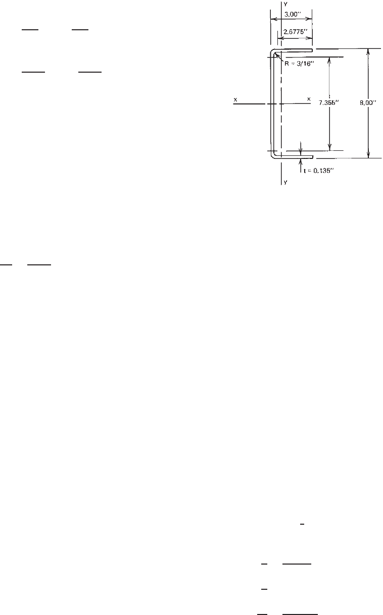
Example 5.3 For the channel section shown in
Fig. 5.26:
1. Determine the critical length L
cr
below
which the flexural–torsional buckling mode is
critical.
2. Use the ASD and LRFD methods to determine the
available strengths if the load is applied through the
centroid of the effective section.
Assume that K
x
L
x
= K
y
L
y
= K
t
L
t
= 6ft. Use F
y
=
50 ksi.
Figure 5.26 Example 5.3.
SOLUTION
A. ASD Method
1. Sectional Properties of Full Section. By using the
equations given in Part I of the AISI Design Manual
or the methods discussed previously in this book, the
following sectional properties can be computed:
A = 1.824 in.
2
m = 1.040 in. β = 0.7855
I
x
= 17.26 in.
4
J = 0.01108 in.
4
I
y
= 1.529 in.
4
C
w
= 16.907 in.
6
r
x
= 3.076 in. x
0
= 1.677 in.
r
y
= 0.916 in. r
0
= 3.622 in.
2. Critical Unbraced Column Length L
cr
. The discus-
sion of Section 5.4.2 indicates that the c ritical
unbraced column length that divides the flexural and
flexural–torsional buckling modes can be determined
by either a graphic method or a theoretical solution,
as illustrated below.
a. Graphic Method. For the given channel section, the
values of
¯
b/¯a, ¯c/¯a, and t/¯a
2
according to Fig. 5.12
are as follows:
¯a = 8 − 0.135 = 7.865 in.
¯
b = 3 −
1
2
× 0.135 = 2.9325 in.
¯c = 0
¯
b
¯a
=
2.9325
7.865
= 0.373
¯c
¯a
= 0
t
¯a
2
=
0.135
(
7.862
)
2
= 0.0022
DESIGN EXAMPLES 217
From Fig. 5.12, it can be seen that because the
value of t/¯a
2
is so small, it is difficult to obtain
the accurate value of the critical length L
cr
by using
the graphic method.
b. Theoretical Solution. AsshowninFig.5.7and
discussed in Section 5.4.2, the critical length can
be determined by solving the following equation:
P
y
=
(
P
cr
)
3
=
1
2β
[(P
x
+ P
z
) −
(
P
x
+ P
z
)
2
− 4βP
x
P
z
]
Since the same full area is to be used for computing
P
y
,P
x
,andP
z
, the following equation may also be
used to determine L
cr
:
σ
ey
=
1
2β
[(σ
ex
+ σ
t
) −
(
σ
ex
+ σ
t
)
2
− 4βσ
ex
σ
t
]
where
σ
ey
=
π
2
E
K
y
L
y
/r
y
2
=
π
2
(
29,500
)
(
L/0.916
)
2
σ
ex
=
π
2
E
(
K
x
L
x
/r
x
)
2
=
π
2
(
29,500
)
(
L/3.076
)
2
σ
t
=
1
Ar
2
0
GJ +
π
2
EC
w
(
K
t
L
t
)
2
=
1
(
1.824
)(
3.622
)
2
(
11300
)(
0.01108
)
+
π
2
(
29,500
)(
16.907
)
L
2
It should be noted that, in the equations of σ
ey
, σ
ex
,
and σ
t
,K
x
L
x
= K
y
L
y
= K
t
L
t
= L. By solving the
above equations, the critical length is 91.0 in.
3. Nominal and Allowable Loads
a. Nominal Buckling Stress F
n
. In view of the facts
that the channel section is a singly symmetric
section and that the given effective length of 72 in.
is less than the computed critical length of 91 in.,
the nominal axial load for the given compression
member should be governed by flexural–torsional
buckling.
In case the critical length is not known, both
flexural buckling and flexural–torsional buckling
should be considered. The smaller value of the
elastic flexural buckling stress and the elastic
flexural–torsional buckling stress should be used
to compute the nominal buckling stress F
n.
i. Elastic Flexural Buckling Stress.ByusingEq.
(5.56) of Section C4.1.1 of the North Amer-
ican Specification, the elastic flexural buckling
stress about the y axis can be computed as
follows:
K
y
L
y
r
y
=
6 × 12
0.916
= 78.60 < 200 OK
(
F
e
)
y
=
π
2
E
K
y
L
y
/r
y
2
=
π
2
(
29,500
)
(
78.600
)
2
= 47.13 ksi
ii. Elastic Flexural–Torsional Buckling Stress. By
using Eq. (5.57) of Section C4.1.2 of the AISI
Specification, the elastic flexural–torsional
buckling stress can be determined:
(
F
e
)
TF
=
1
2β
(σ
ex
+ σ
t
)
−
(
σ
ex
+ σ
t
)
2
− 4βσ
ex
σ
t
where
σ
ex
=
π
2
E
(
K
x
L
x
/r
x
)
2
=
π
2
(
29,500
)
(
6 × 12/3.076
)
2
= 531.41 ksi
σ
t
=
1
Ar
2
0
GJ +
π
2
EC
w
(
K
t
L
t
)
2
=
1
(
1.824
)(
3.622
)
2
(
11,300
)(
0.01108
)
+
π
2
(
29,500
)(
16.907
)
(
6 × 12
)
2
= 44.92 ksi
Substituting the values of β, σ
ex
,andσ
t
into
the equation of (F
e
)
TF
, the elastic flexural–
torsional buckling stress is
(
F
e
)
TF
= 44.07 ksi <
(
F
e
)
y
= 47.13 ksi
Use F
e
= 44.07 ksi
λ
c
=
F
y
F
e
=
50
44.07
= 1.065 < 1.5
From Eq. (5.54),
F
n
=
0.658
λ
2
c
F
y
=
0.658
1.065
2
(
50
)
= 31.10 ksi
b. Effective Area A
e
218 5 COMPRESSION MEMBERS
i. Flange Elements
w = 3 −
(
R + t
)
= 3 −
(
0.1875 + 0.135
)
= 2.6775 in.
w
t
=
2.6775
0.135
= 19.83 < 60 OK
k = 0.43
λ =
1.052
√
k
w
t
f
E
=
1.052
√
0.43
(
19.83
)
31.10
29,500
= 1.033 > 0.673
ρ = 1 −
0.22/λ
λ
= 1 −
0.22/1.033
1.033
= 0.762
b = ρw =
(
0.762
)(
2.6775
)
= 2.040 in.
ii. Web Elements
w = 8 − 2
(
R + t
)
= 8 − 2
(
0.1875 + 0.135
)
= 7.355 in.
w
t
=
7.355
0.135
= 54.48 < 500 OK
k = 4.0
λ =
1.052
√
4.0
(
54.48
)
31.10
29,500
= 0.930 > 6.673
ρ = 1 −
0.22/0.930
0.930
= 0.821
b = ρw =
(
0.821
)(
7.355
)
= 6.038 in.
Theeffectiveareais
A
e
= A − [2(2.6775 − 2.040)
+ (7.355 − 6.038)](0.135)
= 1.824 − 0.350 = 1.474 in.
2
c. Nominal Axial Load for Column Buckling
(Flexural–Torsional Buckling)
P
n
= A
e
F
n
= (1.474)(31.10) = 45.84 kips
d. Allowable Axial Load. The allowable axial load for
the ASD method is
P
a
=
P
n
c
=
45.84
1.80
= 25.47 kips
B. LRFD Method
From item A above, P
n
= 45.84 kips. The design strength
for the LRFD method is
φ
c
P
n
= (0.85)(45.84) = 38.96 kips
5.13 COMPRESSION MEMBERS HAVING ONE
FLANGE FASTENED TO DECKS OR PANELS
5.13.1 Compression Members Having One Flange
Trough Fastened to Deck or Sheathing
In 1996, new design provisions were added in the AISI
Specification for calculating the weak-axis capacity of
axially loaded C- or Z-sections having one flange attached
to deck or sheathing and the other flange unbraced. The
same design equations with minor modifications are
included in Section D6.1.3 of the 2007 edition of the
North American Specification. Equation (5.79) below was
developed by Glaser, Kaehler, and Fisher,
5.104
and is also
based on the work contained in the reports of Hatch,
Easterling, and Murray,
5.105
and Simaan.
5.106
When a roof purlin or wall girt is subject to wind-
or seismic-generated compression forces, the axial load
capacity of such a compression member is less than that of
a fully braced member but greater than that of an unbraced
member. The partial restraint for weak-axis buckling is a
function of the rotational stiffness provided by the panel-
to-purlin connection. It should be noted that Eq. (5.79)
is applicable only for the roof and wall systems meeting
the conditions listed in Section D 6.1.3 of the North Amer-
ican Specification. This equation is not valid for sections
attached to standing seam roofs.
The following excerpt is adapted from Section D 6.1.3 of
the 2007 edition of the North American Specification.
D6.1.3 Compression Members Having One Flange
Through Fastened to Deck or Sheathing.
These provisions shall apply to C- or Z-sections concentrically
loaded along their longitudinal axis, with only one flange
attached to deck or sheathing with through fasteners.
The nominal axial strength [resistance] of simple span or
continuous C- or Z-sections shall be calculated in accordance
with (a) and (b).
(a) The weak-axis nominal strength [resistance] shall be calcu-
lated in accordance with Eq. (5.79). The safety factor and
the resistance factors given in this section of the specifica-
tion shall be used to determine the allowable axial strength
or design axial strength [factored compressive resistance]
in accordance with the applicable design method in Section
3.3.1, 3.3.2 or 3.3.3:
P
n
=
C
1
C
2
C
3
AE
29,500
(5.79)
COMPRESSION MEMBERS HAVING ONE FLANGE FASTENED TO DECKS OR PANELS 219
= 1.80 (ASD)
φ =
0.85 (LRFD)
0.80 (LSD)
where
C
1
= (0.79x + 0.54) (5.80)
C
2
= (1.17αt + 0.93) (5.81)
C
3
= α(2.5b − 1.63d) + 22.8 (5.82)
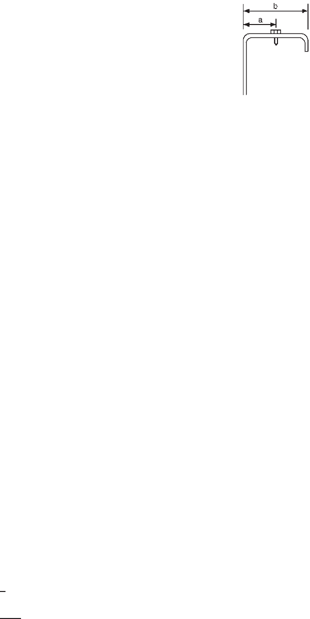
where x = fastener distance from outside web edge
divided by flange width for Z-sections, as
shown in Fig. D6.1.3
= flange width minus fastener distance from
outside web edge divided by flange width for
C-sections, as shown in Fig. D6.1.3
α = coefficient for conversion of units
= 1whent , b,andd are in inches
= 0.0394 when t , b,andd are in millimeters
= 0.394 when t, b,andd are in centimeters
t = C- or Z-section thickness
b = C- or Z-section flange width
d = C- or Z-section depth
A = full unreduced cross-sectional area of C- or
Z-section
E = modulus of elasticity of steel
= 29,500 ksi for U.S. customary units
= 203,000 MPa for SI units
= 2,070,000 kg/cm
2
for MKS units
Eq. (5.79) shall be limited to roof and wall systems
meeting the following conditions:
1. t ≤ 0.125 in.(3.22 mm)
2. 6 in.(152 mm) ≤ d ≤ 12 in.(305 mm)
3. Flanges are edge stiffened compression elements.
4. 70 ≤ d/t ≤ 170
5. 2.8 ≤ d/b < 5
6. 16 ≤ f lange f lat width/t < 50
7. Both flanges prevented from moving laterally at the
supports
8. Both roof or steel wall panels with fasteners spaced 12 in.
(305 mm) on center or less and having a minimum rota-
tional lateral stiffness of 0.0015 k/in./in. (10,300 N/m/m,
or 0.105 kg/cm/cm) (fastener at midflange width for stiff-
ness determination) determined in accordance wit h AISI
S901
9. C- and Z- sections having a minimum yield stress of
33 ksi (230 MPa, or 2320 kg/cm
2
)
10. Span length not exceeding 33 ft (10 m)
(b) The strong-axis available strength [factored resistance] shall
be determined in accordance with Sections C4.1 and C4.1.1
(see Section 5.8 in this volume):
x =
⎧
⎪
⎪
⎨
⎪
⎪
⎩
a
b
for Z-section, (5.83)
b − a
b
for C-section, (5.84)
Figure D6.1.3 Definition of x .
5.13.2 Compression of Z-Section Members Having
One Flange Fastened to a Standing Seam Roof
In 2002, design provisions were prepared for calculating
the weak-axis nominal strengths of concentrically loaded
Z-section members having one flange fastened to a standing
seam roof. Equation (5.85) was developed by Stolarczyk,
Fisher, and Ghorbanpoor
5.198
to predict the lateral buckling
strength on the member using a buckling stress (k
af
RF
y
),
for which the flexural stress (RF
y
) is determined from
uplift tests according to the “Base Test Method for Purlins
Supporting a Standing Seam Roof System” of Part VI of
the AISI Cold-Formed Steel Design Manual.
1.349
It should
be noted that in Eq. (5.85) the gross area A is used instead
of the effective area A
e
because the compressive stress in
the Z-section is generally not large enough to result in a
significant reduction in the effective area. This equation can
only be used for a roof system meeting the conditions listed
in Section D6.1.4 of Appendix A in the North American
specification.
The following excerpt is adapted from Section D6.1.4
(Appendix A) of the 2007 edition of the North American
specification:
1.345
D6.1.4 Compression of Z-Section Members Having
One Flange Fastened to a Standing Seam Roof
These provisions shall apply to Z-sections concentrically
loaded along their longitudinal axis, with only one flange
attached to standing seam roof panels. Alternatively, design
values for a particular system shall be permitted to be based
on discrete point bracing locations or on tests in accordance
with Chapter F.
The nominal axial strength of simple-span or continuous
Z-sections shall be calculated in accordance with (a) and (b).
Unless otherwise specified, the safety factor and the resistance
factor provided in this section of the specification shall be
used to determine the available strengths in accordance with
the applicable method in Section 3.3.1 or 3.3.2.
220 5 COMPRESSION MEMBERS
(a) For weak-axis available strength
P
n
= k
af
RF
y
A (5.85)
= 1.80 (ASD)
φ = 0.85 (LRFD)
where
k
af
=
⎧
⎪
⎪
⎨
⎪
⎪
⎩
0.36 for d/t ≤ 90
0.72 −
d
250t
for 90 <d/t ≤ 130
0.20 for d/t >130
(5.86)
R = reduction factor determined from uplift tests
performed using AISI S908
A = full unreduced cross-sectional area of
Z-section
d = Z-section depth
t = Z-section thickness
See Section 4.2.2 for definition of F
y
.
Equation (5.85) shall be limited to roof system meeting
the following conditions:
1. Purlin thickness, 0.054 in. (1.37 mm) ≤ t ≤ 0.125 in.
(3.22 mm)
2. 6 in. (152 mm) ≤ d ≤ 12 in. (305 mm)
3. Flanges are edge-stiffened compression elements
4. 70 ≤ d /t ≤170
5. 2.8 ≤ d /b < 5, where b = Z-section flange width
6. 16 ≤ f lange f lat width/t < 50
7. Both flanges are prevented from moving laterally at the
supports.
8. Yield stress F
y
≤ 70 ksi (483 MPa, or 4920 kg/cm
2
)
(b) The available strength about the strong axis shall be deter-
mined in accordance with Section C4.1 and C4.1.1 (Section
5.8 in this volume).
5.14 WALL STUDS
It is well known that column strength can be increased
considerably by using adequate bracing, even though the
bracing is relatively flexible. This is particularly true for
those sections generally used as load-bearing wall studs
which have large I
x
/I
y
ratios.
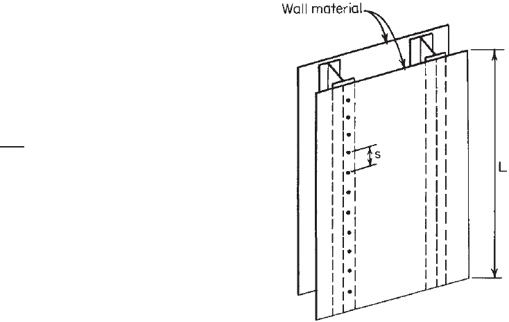
Cold-formed I-, Z-, or C-section or box-type studs are
generally used in walls with their webs placed perpendic-
ular to the w all surface. The walls may be made of different
materials, such as fiber board, pulp board, plywood, or
gypsum board. If the wall material is strong enough and
there is adequate attachment provided between wall mate-
rial and studs for lateral support of the studs, then the
wall material can contribute to the structural economy by
increasing the usable strength of the studs substantially (Fig.
5.27).
Figure 5.27 Wall studs.
In order to determine the necessary requirements for
adequate lateral support of the wall studs, theoretical and
experimental investigations were conducted in the 1940s
by Green, Winter, and Cuykendall.
5.68
This study included
102 tests on studs and 24 tests on a variety of wall material.
It was found that in order to furnish the necessary support
to the studs, the assembly must satisfy the following three
requirements:
1. The spacing between attachments must be c lose
enough to prevent the stud from buckling in the direc-
tion of the wall between attachments.
2. The wall material must be rigid enough to minimize
deflection of the studs in the direction of the wall.
3. The strength of the connection between wall material
and stud must be s ufficient to develop a lateral force
capable of resisting buckling without failure of the
attachment.
Based on the findings of this earlier investigation, specific
AISI provisions were developed for the design of w all
studs. Those provisions and the test procedures based on
the linear spring approach were provided in earlier editions
of the AISI Specification, which was issued by the AISI
from 1946 through 1968.
1.267
In the 1970s, the structural behavior of columns braced
by steel diaphragms was a special subject investigated
at Cornell University and other institutions. The renewed
investigation of wall-braced studs has indicated that the
ADDITIONAL INFORMATION ON COMPRESSION MEMBERS 221
bracing provided for studs by steel panels is of the shear
diaphragm type rather than the linear spring type, which
was considered in the 1947 study. Consequently, the AISI
design criteria for wall studs were revised in 1980 to
reflect the research findings of Simaan and Pekoz.
9.53–9.57
The same provisions were retained in the 1986 edition of
the AISI Specification except that some editorial changes
were made according to the unified design approach. In
1989, the A ISI issued an Addendum to the 1986 edition
of the specification, which states that the wall stud may
be designed either for a bare stud alone or for a structural
assembly on the basis that sheathing (attached to one or
both sides of the stud) furnishes adequate lateral support to
the stud in the plane of the wall and rotational support. In
addition, the 1989 Addendum moves the design limitations
from the Commentary to the Specification and permits stub-
column tests and/or rational analysis for design of studs
with perforations.
In 1996, extensive revisions were made to permit the
use of wall studs having either solid or perforated webs.
Specific limitations are included in the Specification for the
size and spacing of perforations. The same requirements
were retained in the 2001 edition of the North American
Specification. In the 2007 edition of the North American
Specification, the braced design provisions were deleted
and a requirement was added that wall studs shall be
designed in accordance with the Wall Stud Design Stan-
dard (AISI S211) or solely in accordance with the North
American Specification either on the basis of an all-steel
design system or on the basis of sheathing braced design
in accordance with appropriate theory, tests, or rational
engineering analysis. Details of the current North Amer-
ican design provisions are discussed in Sections 9.3 and
13.2.2.4.
5.15 ADDITIONAL INFORMATION ON
COMPRESSION MEMBERS
During the past years, additional analytical and experi-
mental studies have been conducted by many investiga-
tors. References 5.69–5.92 report on the research findings
on doubly symmetric sections, box sections, channels, Z-
sections, and multicell plate columns. The s trength evalua-
tion and design of cold-formed steel columns are discussed
in Refs. 5.93–5.99. Refere nces 5.116–5.140, 5.199–5.206,
5.208, and 5.209 report on more studies on compression
members. Additional publications can be found from other
conference proceedings and engineering journals.
CHAPTER 6
Combined Axial Load
and Bending
6.1 GENERAL REMARKS
Structural members are often subject to combined bending
and axial load either in tension or in compression. In the
1996 edition of the AISI Specification, the design provi-
sions for combined axial load and bending were expanded
to include specific requirements in Section C5.1 for the
design of cold-formed steel structural members s ubjected to
combined tensile axial load and bending. The same require-
ments are retained in the North American Specification.
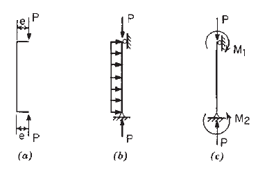
When structural members are subject to combined
compressive axial load and bending, the design provisions
are given in Section C5.2 of the North American Spec-
ification. This type of member is usually referred to as
a beam–column. The bending may result from eccentric
loading (Fig. 6.1a), transverse loads (Fig. 6.1b), or applied
moments (Fig. 6.1c). Such members a re often found in
framed structures, trusses, and exterior wall studs. In
steel structures, beams are usually supported by columns
through framing angles or brackets on the sides of the
columns. The reactions of beams can be considered as
eccentric loading, which produces bending moments.
The structural behavior of beam–columns depends on the
shape and dimensions of the cross section, the location of
the applied eccentric load, the column length, the condition
of bracing, and so on. For this reason, previous editions of
the AISI Specification have subdivided design provisions
into the following four cases according to the configuration
of the cross section and the type of buckling mode
1.4
:
1. Doubly symmetric shapes and shapes not subjected to
torsional or flexural–torsional buckling
Figure 6.1 Beam–columns: (a) subject to eccentric loads;
(b) subject to axial and transverse loads; (c). subject to axial loads
and end moments.
2. Locally stable singly symmetric shapes or intermit-
tently fastened components of built-up shapes, which
may be subject to flexural–torsional buckling, loaded
in the plan of symmetry
3. Locally unstable symmetric shapes or intermittently
fastened components of built-up shapes, which may
be subject to flexural–torsional buckling, loaded in
the plan of symmetry
4. Singly symmetric shapes which are unsymmetrically
loaded
The early AISI design provisions for singly symmetric
sections subjected to combined compressive load and
bending were based on an extensive investigation of
flexural–torsional buckling of thin-walled sections under
eccentric load conducted by Winter, Pekoz, and Celibi at
Cornell University.
5.66,6.1
The behavior of c hannel columns
subjected to eccentric loading has also been studied by
Rhodes, Harvey, and Loughlan.
5.34,6.2–6.5
In 1986, as a result of the unified approach, Pekoz indi-
cated that both locally stable and unstable beam–columns
can be designed by the simple, well-known interaction
equations as included in Section C5 of the AISI Speci-
fication. The justification of the AISI design criteria was
given in Ref. 3.17. The 1996 design criteria were verified
by Pekoz and Sumer using the available test results.
5.103
In the 2007 edition of the North American Specification,
in addition to the use of the first-order elastic analysis to
compute the required compressive axial strength (P)and
flexural strengths (M
x
and M
y
), reference is also made for
the use of the second-order analysis in accordance with
Appendix 2 of the Specification. Furthermore, the Specifica-
tion also requires that each individual ratio in the interaction
equations shall not exceed unity.
223
224 6 COMBINED AXIAL LOAD AND BENDING
6.2 COMBINED TENSILE AXIAL LOAD
AND BENDING
6.2.1 Tension Members
For the design of tension members using hot-rolled
steel shapes and built-up members, the AISC Specifi-
cations
1.148,3.150,1.411
provide design provisions for the
following three limit states: (1) yielding of the full section
between connections, (2) fracture of the effective net area
at the connection, and (3) block shear fracture at the
connection.
For cold-formed steel design, Section C2 of the 1996
AISI Specification provided Eq. (6.1) for calculating the
nominal tensile strength of axially loaded tension members,
with a safety factor for the ASD method and a resistance
factor for the LRFD method as follows:
T
n
= A
n
F
y
(6.1)
t
= 1.67 (ASD)
φ
t
= 0.95 (LRFD)
where T
n
= nominal tensile strength
A
n
= net area of the cross section
F
y
= design yield s tress
In addition, the nominal tensile strength was also limited
by Section E.3.2 of the 1996 Specification for tension in
connected parts.
When a tension member has holes, s tress concentration
may result in a higher tensile stress adjacent to a hole to
be about three times the average stress on the net area.
6.36
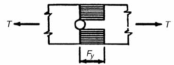
With increasing load and plastic stress redistribution, the
stress in all fibers on the net area will reach the yield stress,
as shown in Fig. 6.2. Consequently, the AISI specification
has used Eq. (6.1) for determining the maximum tensile
capacity of axially loaded tension members since 1946.
This AISI design approach differs significantly from the
AISC design provisions, which consider yielding of the
gross cross-sectional area, fracture of the effective net area,
and block shear. The reason for not considering the fracture
criterion in the 1996 AISI Specification was mainly due to
the lack of research data relative to the shear lag e ffect on
tensile strength of cold-formed steel members.
Figure 6.2 Stress distribution for nominal tensile strength.
In 1995, the influence of shear lag on the tensile capacity
of bolted connections in cold-formed steel angles and c han-
nels was investigated by Carril, Holcomb, LaBoube, and
Yu at the University of Missouri-Rolla. Design equations
were recommended in R efs. 6.23–6.25 for computing
the effective net area. This design information enables
the consideration of fracture s trength at connections for
angles and channels. The same study also investigated
the tensile strength of staggered bolt patterns in flat-sheet
connections.
On the basis of the results of past research, Section C2 of
the Specification was revised in 1999. This AISI Supple-
ment to the specification included revised provisions for
the design of axially loaded tension members.
1.333
The
same design provisions were included in Section C2 of
Appendix A of the North American Specifications
1.336,1.346
for the design of tension members in the United States and
Mexico. In Canada, the design of tension members has been
based on Appendix B of the 2007 edition of the North
American Specification.
The following design requirements are adapted from
Section C2 of Appendix A of the 2007 edition of the North
American Specification.
C2 Tension Members
For axially loaded tension members, the nominal tensile
strength, T
n
, shall be the smaller value obtained in accor-
dance with the limit states of (a), (b), and (c). Unless otherwise
specified, the corresponding safety factor and resistance factor
provided in this section of the Specification shall be used to
determine the available strengths in accordance with the appli-
cable method in Sections 3.3.1 or 3.3.2.
(a) For yielding in gross section:
T
n
= A
g
F
y
(6.2)
t
= 1.67 (ASD)
φ
t
= 0.90 (LRFD)
where T
n
= nominal strength of member when loaded in
tension
A
g
= gross area o f cross section
F
y
= yield stress as specified in Section A7.1
(b) For rupture in the net section away from connection:
T
n
= A
n
F
u
(6.3)
t
= 2.00 (ASD)
φ
t
= 0.75 (LRFD)
where A
n
= net area o f cross section
F
u
= tensile strength as specified in Section A2.1
or A2.3.2