Yu W., LaBoube R.A. Cold-Formed Steel Design
Подождите немного. Документ загружается.

COMBINED COMPRESSIVE AXIAL LOAD AND BENDING (BEAM–COLUMNS) 225
(c) For rupture in net section at connection: The avail-
able tensile strength shall also be limited by Sections
E2.7, E.3, and E5 for tension members using welded
connections, bolted connections, and screw connections,
respectively.
From the above requirements, it can be seen that the
nominal tensile strength of axially loaded cold-formed steel
members is determined either by yielding of gross sectional
area or by rupture of the net area of the cross section. At
connections, the nominal tensile strength is also limited by
the capacities determined in accordance with Sections E2.7,
E3, and E5 of the Specification for tension in connected
parts. In addition to the strength consideration, yielding in
the gross section also provides a limit on the deformation
that a tension member can achieve.
6.2.2 Members Subjected to Combined Tensile
Axial Load and Bending
When cold-formed steel members are subject to concurrent
bending and tensile axial load, the member shall satisfy the
interaction equations given below which are prescribed in
Section C5.1 of the North American Specification for the
ASD, LRFD, and LSD methods.
C5.1 Combined Tensile Axial Load and Bending
C5.1.1 ASD Method
The required strengths T, M
x
,andM
y
shall satisfy the
following interaction equations:
b
M
x
M
nxt
+
b
M
y
M
nyt
+
t
T
T
n
≤ 1.0 (6.4a)
and
(6.4b)
b
M
x
M
nx
+
b
M
y
M
ny
−
t
T
T
n
≤ 1.0
where
b
= 1.67
M
x
, M
y
= required flexural strengths with respect to
centroidal axes of section
M
nxt
,M
nyt
= S
ft
F
y
S
ft
= section modulus of full unreduced section
relative to extreme tension fiber about
appropriate axis
F
y
= design yield stress determined in accordance
with Section A7.1
t
= 1.67
T = required tensile axial strength
T
n
= nominal tensile axial strength determined in
accordance with Section C2
M
nx
,M
ny
= nominal flexural strengths about centroidal axes
determined in accordance with
Section C3.1
C5.1.2 LRFD and LSD Methods
The required strengths [factored tension and moments] T , M
x
,
and
M
y
shall satisfy the following interaction equations:
M
x
φ
b
M
nxt
+
M
y
φ
b
M
nyt
+
T
φ
t
T
n
≤ 1.0 (6.5a)
M
x
φ
b
M
nx
+
M
y
φ
b
M
ny
−
T
φ
t
T
n
≤ 1.0 (6.5b)
where
M
x
, M
y
are the required flexural strengths [factored
moments] with respect to centroidal axes:
M
x
= M
ux
M
y
= M
uy
(LRFD)
M
x
= M
fx
M
y
= M
fy
(LSD)
and φ
b
for flexural strength [moment resistance] (Section
C3.1.1) equals 0.90 or 0.95 (LRFD) and 0.90 ( LSD). For
laterally unbraced beams (Section C3.1.2), φ
b
= 0.90 (LRFD
and LSD) and for closed cylindrical tubular members (Section
C3.1.3), φ
b
= 0.95 (LRFD) and 0.90 (LSD).
where M
nxt
,M
nyt
= S
ft
F
y
S
ft
= section modulus of full unreduced section
relative to extreme tension fiber about
appropriate axis
F
y
= design yield stress determined in accordance
with Section A7.1
T = required tensile axial strength [factored tension]
= T
u
(LRFD)
= T
f
(LSD)
φ
t
= 0.95 (LRFD)
= 0.90 (LSD)
T
n
= nominal tensile axial strength [resistance]
determined in accordance with Section C2
M
nx
,M
ny
= nominal flexural strengths [moment resistances]
about centroidal axes determined in accordance
with Section C3.1
In the North American specification, Eq. (6.4a) serves as
an ASD design criterion to prevent yielding of the tension
flange of the member s ubjected to combined tensile axial
load and bending. Equation (6.4b) provides a requirement
to prevent failure of the compression flange.
For the LRFD and LSD methods, Eqs. (6.5a) and (6.5b)
are used to prevent the failure of the tension flange and
compression flange, respectively.
6.3 COMBINED COMPRESSIVE AXIAL LOAD
AND BENDING (BEAM–COLUMNS)
6.3.1 Shapes Not Subjected to Torsional
or Flexural–Torsional Buckling
1.161
When a doubly symmetric open section is subject to axial
compression and bending about its minor axis, the member
may fail flexurally at the location of the maximum moment
226 6 COMBINED AXIAL LOAD AND BENDING
by either yielding or local buckling. However, when the
section is subject to an eccentric load that produces a
bending moment about its major axis, the member may
fail flexurally or in a flexural–torsional mode because the
eccentric load does not pass through the shear center.
For torsionally stable shapes, such as closed rectangular
tubes, when the bending moment is applied about the
minor axis, the member may fail flexurally in the region
of maximum moment, but when the member is bent about
its major axis, it can fail flexurally about the major or minor
axis, depending on the amount of eccentricities.
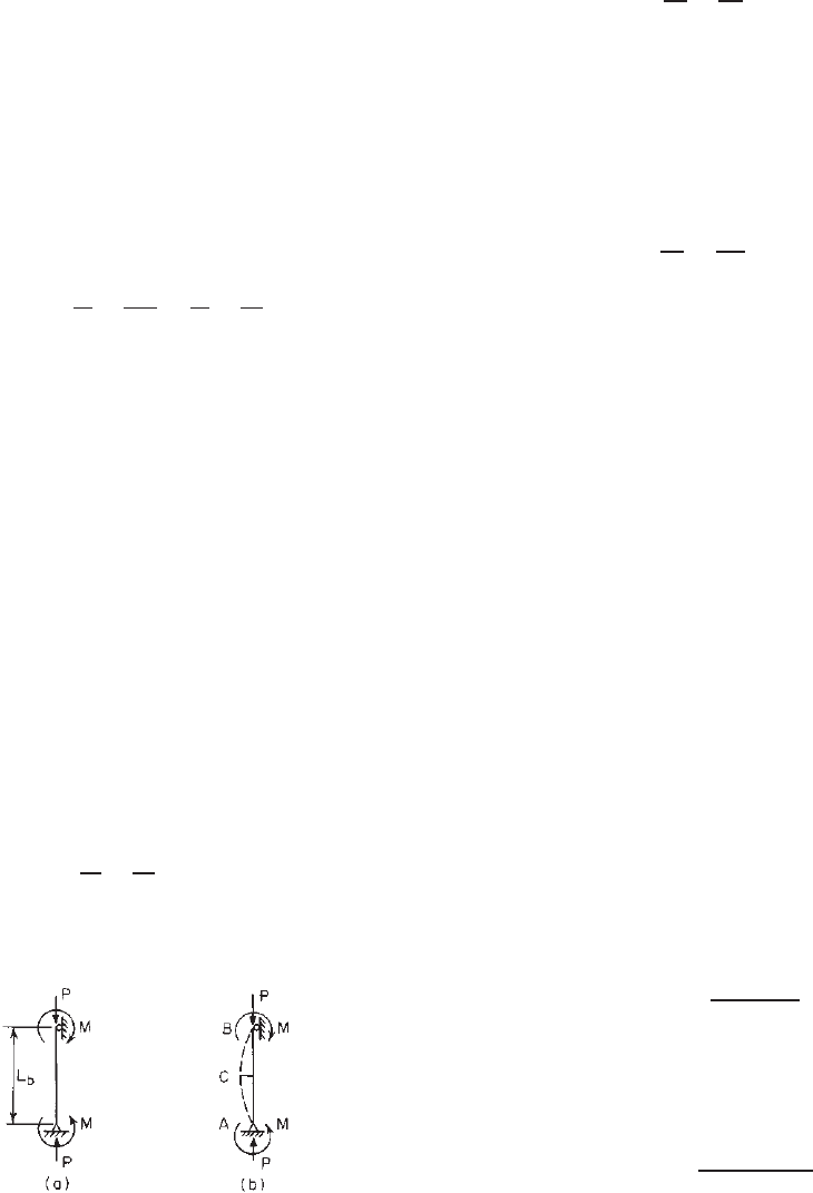
If a doubly symmetric I-section is subject to an axial
load P and end moments M, as shown in Fig. 6.3a,the
combined axial and bending stress in compression is given
in Eq. (6.6) as long as the member remains straight:
f =
P
A
+
Mc
I
=
P
A
+
M
S
= f
a
+ f
b
(6.6)
where f =combined stress in compression
f
a
= axial compressive stress
f
b
= bending stress in compression
P = applied axial load
A = cross-sectional area
M = bending moment
c = distance from neutral axis to extreme fiber
I = moment of inertia
S = section modulus
It should be noted that in the design of such a
beam–column using the ASD method, the combined stress
should be limited by certain allowable stress F, that is,
f
a
+ f
b
≤ F (6.7)
or
f
a
F
+
f
b
F
≤ 1.0
Figure 6.3 Beam–column subjected to axial loads and end
moments.
As discussed in Chapters 3, 4, and 5, the safety factor
for the design of compression members is different from
the s afety factor for beam design. Therefore, Eq. (6.7) may
be modified as follows:
f
a
F
a
+
f
b
F
b
≤ 1.0 (6.8)
where F
a
= allowable stress for design of compression
members
F
b
= allowable stress for design of beams
If the strength ratio is used instead of the stress ratio,
Eq. (6.8) can be rewritten as follows:
P
P
a
+
M
M
a
≤ 1.0 (6.9)
where P = applied axial load, =Af
a
P
a
= allowable axial load, =AF
a
M = applied moment, =Sf
b
M
a
= allowable moment, =SF
b
Equation (6.9) is a well-known interaction formula which
has been adopted in some ASD specifications for the design
of beam–columns. It can be used with reasonable accuracy
for short members and members subjected to a relatively
small axial load. It should be realized that in practical
application, when end moments are applied to the member,
it will be bent, as shown in Fig. 6.3b, due to the applied
moment M and the secondary moment resulting from the
applied axial load P and the deflection of the member. The
maximum bending moment at midlength (point C ) can be
represented by
M
max
= M (6.10)
where M
max
= maximum bending moment at midlength
M = applied end moments
= amplification factor
It can be shown that the amplification factor may be
computed by
1.161,2.45
=
1
1 − P/P
e
(6.11)
where P
e
= π
2
EI(KL
b
)
2
is the elastic column buckling load
(Euler load).
Applying a safety factor
c
to P
e
, Eq. (6.11) may be
rewritten as
=
1
1 −
c
P/P
e
(6.12)
If the maximum bending moment M
max
is used to replace
M, the following interaction formula can be obtained from
COMBINED COMPRESSIVE AXIAL LOAD AND BENDING (BEAM–COLUMNS) 227
Eqs. (6.9) and (6.12):
P
P
a
+
M
M
a
≤ 1.0 (6.13)
or
P
P
a
+
M
(1 −
c
P/P
e
)M
a
≤ 1.0
It has been found that Eq. (6.13), developed for a member
subjected to an axial compressive load and equal end
moments, can be used with reasonable accuracy for braced
members with unrestrained ends subjected to an axial
load and a uniformly distributed transverse load. However,
it could be conservative for compression members in
unbraced frames (with sidesway) and for members bent in
reverse curvature. For this reason, the interaction formula
given in Eq. (6.13) should be further modified by a coeffi-
cient C
m
, as shown in Eq. (6.14), to account for the effect
of end moments:
P
P
a
+
C
m
M
(1 −
c
P/P
e
)M
a
≤ 1.0 (6.14)
In Eq. (6.14) C
m
can be computed by Eq. (6.15) for
restrained compression members braced against joint trans-
lation and not subjected to transverse loading:
C
m
= 0.6 − 0.4
M
1
M
2
(6.15)
where M
1
/M
2
is the ratio of the smaller to the larger end
moment.
When the maximum moment occurs at braced points,
Eq. (6.16) should be used to check the member at the braced
ends:
P
P
a0
+
M
M
a
≤ 1.0 (6.16)
where P
a0
is the allowable axial load for KL/r = 0.
Furthermore, for the condition of small axial load, the
influence of C
m
/(1 −
c
P/P
e
) is usually small and may
be neglected. Therefore when P ≤ 0.15P
a
,Eq.(6.9)may
be used for the design of beam–columns.
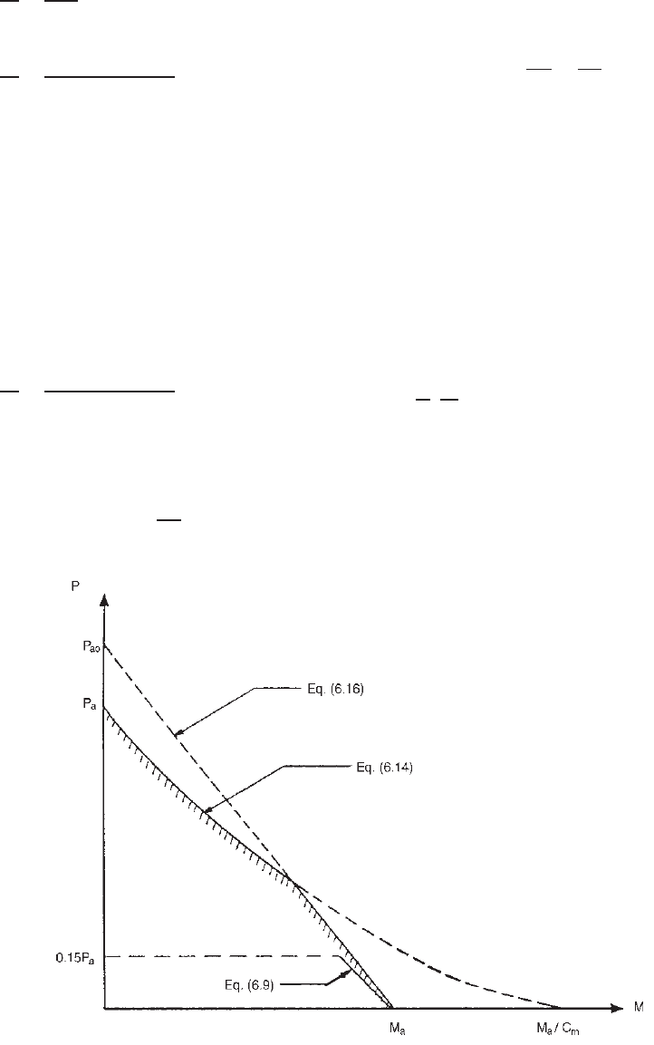
The interaction relations between Eqs. (6.9), (6.14), and
(6.16) are shown in Fig. 6.4. If C
m
is unity, Eq. (6.14)
controls over the entire range.
Substituting P
a
= P
n
/
c
, P
a0
= P
n0
/
c
,andM
a
=
M
n
/
b
into Eqs. (6.9), (6.14), and (6.16), the interaction
equations for the ASD method (Section C5.2.1 of the
North American specification) can be obtained. Similarly,
the interaction equations for the LRFD and LSD methods
(Section C5.2.2 of the specification) can be obtained by
using
P , M, φ
c
P
n
,andφ
b
M
n
.
6.3.2 Open Sections That May Be Subject
to Flexural–Torsional Buckling
5.66,6.1
When singly symmetric and nonsymmetric open sections
are used as beam–columns, these members may be subject
Figure 6.4 Interaction relations for the ASD method.
228 6 COMBINED AXIAL LOAD AND BENDING
to flexural–torsional buckling. The following discussion is
based primarily on Ref. 6.1.
The differential equations of equilibrium governing
the elastic behavior of such members are given in
Eqs. (6.17)–(6.19)
3.2
:
EI
x
v
iv
+ Pv
− Px
0
φ
+ M
y
φ
= 0 (6.17)
EI
y
u
iv
+ Pu
+ Py
0
φ
− M
x
φ
= 0 (6.18)
EC
w
φ
iv
− GJφ
+ (P r
2
0
+ β
x
M
x
+ β
y
M
y
)φ
+Py
0
u
− Px
0
v
− M
x
u
+ M
y
v
= 0 (6.19)
where I
x
= moment of inertia about x axis
I
y
= moment of inertia about y axis
u = lateral displacement in x direction
v = lateral displacement in y irection
φ = angle of rotation
x
0
= x coordinate of shear center
y
0
= y coordinate of shear center
E = modulus of elasticity, =29.5 × 10
3
ksi
(203 GPa, or 2.07 × 10
6
kg/cm
2
)
G = shear modulus, =11.3 × 10
3
ksi (78 GPa, or
794 × 10
3
kg/cm
2
)
J = St. Venant torsion constant of cross section,
1
3
l
i
t
3
i
C
w
= warping constant of torsion of cross section
(Appendix B)
r
0
= polar radius of gyration of cross section about
shear center, =
√
I
0
/A =
r
2
x
+ r
2
y
+ x
2
0
+ y
2
0
P = applied concentric load
M
x
,M
y
= bending moments about x and y axes,
respectively
and
β
x
=
1
I
x
A
y
x
2
+ y
2
dA − 2y
0
(6.20)
β
y
=
1
I
y
A
x(x
2
+ y
2
)dA− 2x
0
(see Appendix C)
(6.21)
All primes are differentiations with respect to the z axis.
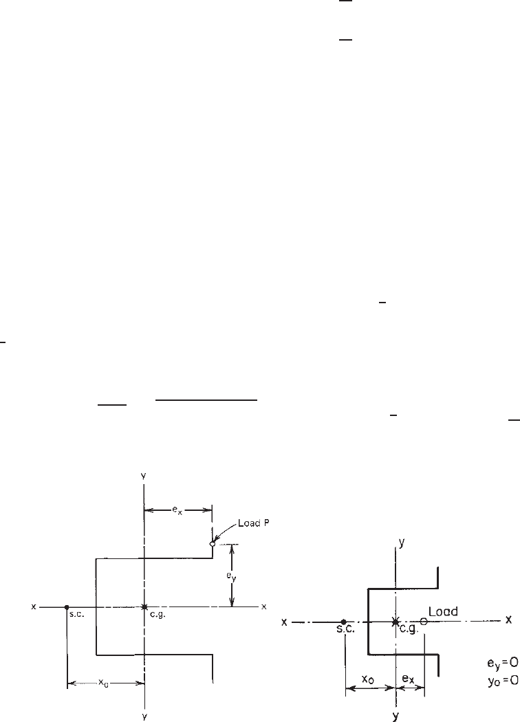
Assume that the end moments M
x
and M
y
are due to
the eccentric loads applied at both ends of the column with
equal biaxial eccentricities e
y
and e
x
(Fig. 6.5). Then the
moments M
x
and M
y
can be replaced by
M
x
= Pe
y
(6.22)
M
y
= Pe
x
(6.23)
Consequently, Eqs. (6.17)–(6.19) can be rewritten as
EI
x
v
iv
+ Pv
− Pa
x
φ
= 0 (6.24)
EI
y
u
iv
+ Pu
+ Pa
y
φ
= 0 (6.25)
EC
w
φ
iv
+
P r
2
0
− GJ
φ
+ Pa
y
u
− Pa
x
v
= 0 (6.26)
where
a
x
= x
0
− e
x
(6.27)
a
y
= y
0
− e
y
(6.28)
r
2
0
= β
x
e
y
+ β
y
e
x
+
I
0
A
(6.29)
(a) (b)
Figure 6.5 (a) Unsymmetrically loaded hat section. (b) Hat section subjected to an eccentric
load in the plane of symmetry.
COMBINED COMPRESSIVE AXIAL LOAD AND BENDING (BEAM–COLUMNS) 229
Table 6.1 Coefficients K
6.1
Boundary
Conditions
at z = 0, LK
11
K
22
K
33
K
1
K
2
K
3
K
13
K
31
K
23
K
32
K
23
u
= v
= φ
= 0 1.0000 1.0000 1.0000 1.2732 1.2732 1.2732 1.0000 1.0000 1.0000 1.0000 1.0000
u
= v
= φ
= 0 1.0000 4.1223 1.0000 1.2732 ... 1.2732 1.0000 1.0000 0.5507 1.4171 0.8834
u
= v
= φ
= 0 4.1223 4.1223 1.0000 ... ... 1.2732 0.5507 1.4171 0.5507 1.4171 0.8834
u
= v
= φ
= 0 1.0000 4.1223 4.1223 1.2732 ... 0.6597 1.4171 0.5507 1.0000 0.8834 1.0000
u
= v
= φ
= 0 4.1223 4.1223 4.1223 ... ... 0.6597 1.0000 1.0000 1.0000 1.0000 1.0000
u
= v
= φ
= 0 1.0000 1.0000 4.1223 1.2732 1.2732 0.6597 1.4171 0.5507 1.4171 0.5507 0.8834
The solution of Eqs. (6.24) – (6.26) is shown in Eq. (6.30)
by using Galerkin’s method:
⎡
⎢
⎣
P
ey
− P 0 −Pa
y
K
13
0 P
ex
− PPa
x
K
23
−Pa
y
K
31
Pa
x
K
32
r
2
0
(P
ex
− P)
⎤
⎥
⎦
⎧
⎨
⎩
u
0
v
0
φ
0
⎫
⎬
⎭
=
⎧
⎪
⎪
⎪
⎪
⎪
⎪
⎪
⎪
⎨
⎪
⎪
⎪
⎪
⎪
⎪
⎪
⎪
⎩
−
P
2
P
ey
e
x
K
1
−
P
2
P
ex
e
y
K
2
−P
2
a
y
e
x
P
ey
−
a
x
e
y
P
ex
K
3
⎫
⎪
⎪
⎪
⎪
⎪
⎪
⎪
⎪
⎬
⎪
⎪
⎪
⎪
⎪
⎪
⎪
⎪
⎭
(6.30)
where
P
ey
= K
11
π
2
EI
y
L
2
(6.31)
P
ex
= K
22
π
2
EI
x
L
2
(6.32)
P
ez
=
1
r
2
0
K
33
EC
w
π
2
L
2
+ GJ
(6.33)
and u
0
, v
0
,andφ
0
are coefficients for deflection compo-
nents. The coefficients K for various boundary conditions
are listed in Table 6.1.
6.3.3 Singly Symmetric Open Shapes
Channels, angles, and hat sections are some of the singly
symmetric open s hapes. If these members are subject to
bending moments in the plane of symmetry (x axis, as
shown in Fig. 5.6), they may fail in one of the following
two ways
∗
:
∗
If twisting is prevented by properly designed bracing, the member will fail
only flexurally by yielding or local buckling. When the bending moment
is applied in any plane other than the plane of symmetry, the member will
fail in the flexural–torsional buckling mode.
1. The member deflects gradually in the plane of
symmetry without twisting and finally fails by
yielding or local buckling at the location of
maximum moment.
2. The member starts with a gradual flexural bending in
the plane of symmetry, but when the load reaches a
critical value, the member will suddenly buckle by
flexural–torsional buckling.
The type of failure mode, which will govern the
maximum strength of the member, depends on the shape
and dimensions of the cross section, the column length,
and the eccentricity of the applied load.
The structural behavior discussed above can be
explained by the solution of differential equations [Eqs.
(6.24)–(6.26)]. When the eccentric load is applied in the
plane of symmetry of the section, as shown in Fig. 6.5b,
e
y
= y
0
= 0. Equation (6.30) can be changed to the
following two formulas:
(P
ey
− P)u
0
=−
P
2
P
ey
e
x
K
1
(6.34)
P
ex
− PPa
x
K
23
Pa
x
K
32
r
2
0
(P
ex
− P)
v
0
φ
0
= 0 (6.35)
in which Eq. (6.34) represents the behavior of a
beam–column deforming flexurally without twist and
Eq. (6.35) is related to flexural–torsional buckling.
If flexural failure governs the maximum strength of the
beam–column, the design of singly symmetric shapes is to
be based on the interaction formulas similar to those used
in Section 6.3.1 for doubly symmetric shapes.
However, if the singly symmetric section fails in
flexural–torsional buckling, the following critical buckling
load can be determined by the equation derived from
Eq. (6.35) by setting the determinant of the coefficient
230 6 COMBINED AXIAL LOAD AND BENDING
equal to zero:
P
TF
=
(
P
ex
+ P
ez
)
±
(
P
ex
+ P
ez
)
2
− 4βP
ex
P
ez
2β
(6.36)
where
β = 1 −
(
x
0
− e
x
)
2
r
2
0
K
2
23
(6.37)
For members having simply supported ends and subjected
to concentric loading (that is, e
x
= 0, K
23
= 1.0), Eq. (6.36)
can be changed to Eq. (6.38), which was used in Section
5.4.2 for axially loaded compression members:
P
TFO
=
1
2β
[(P
x
+ P
z
) −
(P
x
+ P
z
)
2
− 4βP
x
P
z
(6.38)
in which β = 1 − (x
0
/r
0
)
2
as previously defined in
Chapter 5.
From Eq. (6.36) it can be seen that the computation of
the flexural–torsional buckling load is time consuming for
design use. A previous study made by Pek
¨
oz, C elebi, and
Winter indicated that the flexural–torsional buckling load
may be computed by the following interaction formula if
the load is applied on the side of the centroid opposite from
that of the shear center
6.1
:
P
TF
P
TFO
+
P
TF
e
x
M
T
= 1.0 (6.39)
where P
TF
= flexural–torsional buckling load for
eccentric load having an eccentricity of e
x
P
TFO
= flexural–torsional buckling load for
concentric load [Eq. (6.38)]
M
T
= critical moment causing tension on shear
center side of centroid
In Eq. (6.39), if we apply the modification factor given
in the equation
C
TF
1 − P
TF
/P
e
(6.40)
to the moment P
TF
e
x
, as done previously in Section 6.3.1,
the interaction formula can be written as
P
TF
P
TFO
+
C
TF
(
P
TF
e
x
)
(
1 − P
TF
/P
e
)
M
T
= 1.0 (6.41)
In the above equation, the factor C
TF
is the same as C
m
used in Section 6.3.1.
Equation (6.41) can be used to determine the theoret-
ical elastic flexural–torsional buckling load P
TF
for singly
symmetric sections under eccentric loads applied on the
side of the centroid opposite from that of the shear center.
The critical moment M
T
used in Eq. (6.41) can be
obtained from the following equation:
M
T
=−
1
2K
2
23
β
y
P
ex
−
(β
y
P
ex
)
2
+ 4K
2
23
P
ex
P
ez
I
0
A
(6.42)
where
P
ez
= P
ez
1 +
e
x
β
y
A
I
0
(6.43)
K
23
=
K
23
K
23
(see Table 6.1) (6.44)
For s imply supported end conditions, Eq. (6.42) can be
simplified and rearranged as
M
T
=−P
ex
j −
j
2
+ r
2
0
P
ez
P
ex
(6.45)
or
M
T
=−Aσ
ex
j −
j
2
+ r
2
0
σ
t
σ
ex
(6.46)
where
j =
β
y
2
=
1
2I
y
A
x
3
dA +
A
xy
2
dA
− x
0
(6.47)
σ
ex
=
π
2
E
(
K
x
L
x
/r
x
)
2
(6.48)
σ
t
=
1
Ar
2
0
GJ +
π
2
EC
w
(
K
t
L
t
)
2
(6.49)
If the eccentric load is applied on the side of the
shear center opposite from that of the centroid, the crit-
ical moment causing compression on the shear center side
of the centroid, M
c
, can be computed as follows:
M
c
= Aσ
ex
j +
j
2
+ r
2
0
σ
t
σ
ex
(6.50)
Both Eqs. (6.46) and (6.50) were used in Eq. (4.54) for
determining the elastic critical moment for latera1–tosional
buckling strength.
For the ASD method, the allowable load for
flexural–torsional buckling in the elastic range can
be derived from P
TF
by using a safety factor of 1.80. The
inelastic buckling stress can be computed by the equation
that was used for flexural–torsional buckling of axially
loaded compression members (Chapter 5).
So far we have discussed the possible failure modes for
a singly symmetric section under eccentric load. H owever,
the type of failure that will govern the maximum strength
of the beam–column depends on which type of failure falls
below the other for the given eccentricity. This fact can
be shown in Fig. 6.6a. For the given hat section having
COMBINED COMPRESSIVE AXIAL LOAD AND BENDING (BEAM–COLUMNS) 231
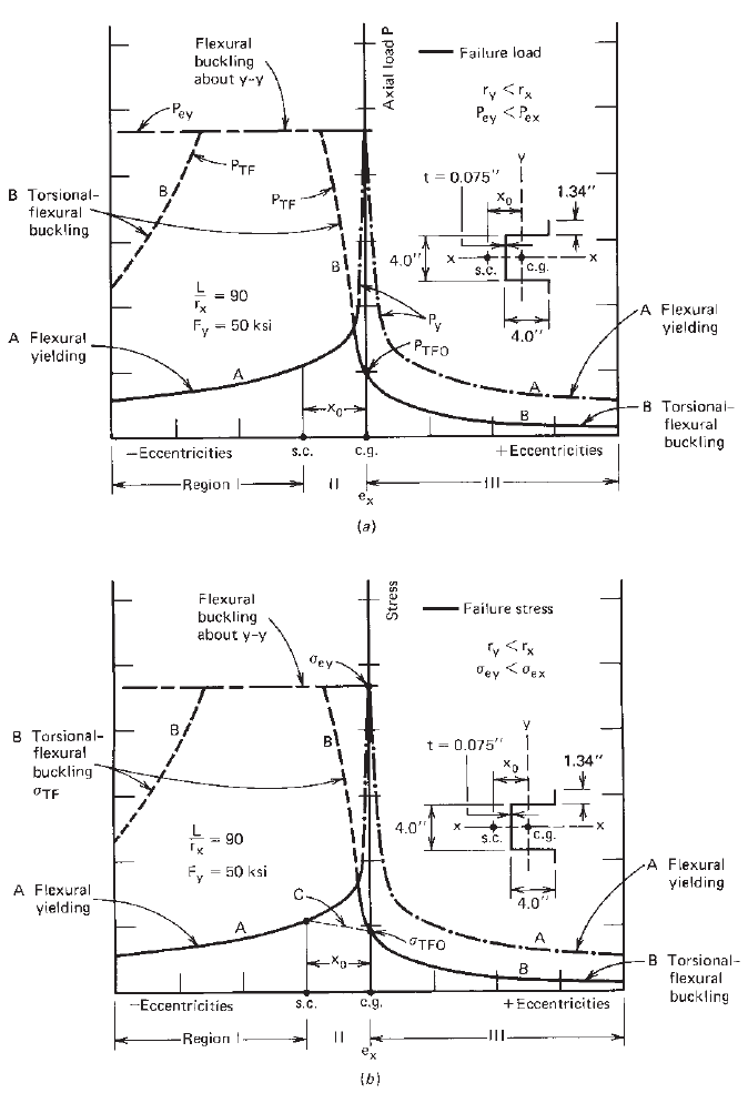
Figure 6.6 Strength of eccentrically loaded hat section
6.1
:(a)loadvs.e
x
; (b)stressvs.e
x
.
L/r
x
= 90, the section will fail in flexural yielding if
the load is applied in region I. Previous study has indi-
cated that for channels, angles, and hat sections the section
always fails in flexural yielding when the eccentricity is
in region I (that is, e
x
< −x
0
). When the eccentricity is in
region III (that is, 0 <e
x
), the section can fail either in flex-
ural yielding or in flexural–torsional buckling. Therefore,
both conditions (flexural yielding and flexural–torsional
buckling) should be checked. For the given hat section
shown in Fig. 6.6a, when the load is applied at the center of
gravity, the section will buckle flexural–torsionally at a load
P
TFO
that is smaller than the flexural buckling load P
ey
.At
a certain eccentricity in region II (that is, −x
0
<e
x
< 0),
the failure mode changes from flexural–torsional buckling
to simple flexural failure. It can also be seen that in this
region small changes in eccentricity result in large changes
232 6 COMBINED AXIAL LOAD AND BENDING
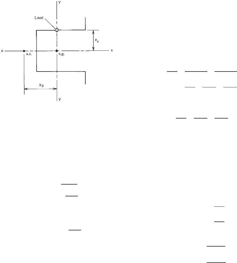
Figure 6.7 Hat section subjected to an eccentric load applied
along the y axis.
in failure load. Thus any small inaccuracy in eccentricity
could result in nonconservative designs.
For bending about the axis of symmetry (i.e., when the
eccentric load is applied along the y axis as shown in
Fig. 6.7), the following equation for determining the elastic
critical moment can be derived from Eq. (6.30) on the basis
of e
x
= 0, e
y
= 0, P = 0, and Pe
y
= M
6.1
x
:
M
x
= r
0
P
ey
P
ez
= r
0
A
√
σ
ey
σ
t
(6.51)
For the case of unequal end moments, Eq. (6.51) may be
modified by multiplying by a bending coefficient C
b
as
follows:
M
x
= C
b
r
0
A
√
σ
ey
σ
t
(6.52)
The above equation was used in Eq. (4.51) for
lateral–torsional buckling strength consideration.
6.4 NORTH AMERICAN DESIGN CRITERIA
The following are the design provisions adapted from
Section C5.2 of the 2007 edition of the North American
specification for the design of beam–columns.
C5.2 Combined Compressive Axial Load and Bending
C5.2.1 ASD Method
The required strengths P , M
x
,andM
y
shall be determined
using first-order elastic analysis and shall satisfy the following
interaction equations. Alternatively, the required strengths
P, M
x
,andM
y
shall be determined in accordance with
Appendix 2 in the Specification and shall satisfy the following
interaction equations using the values for K
x
, K
y
, α
x
, α
y
,
C
mx
,andC
my
specified in Appendix 2 in the Specification. In
addition, each individual ratio in Eqs. (6.53)–(6.55) shall not
exceed unity.
For singly symmetric unstiffened angle sections with unre-
duced effective area, M
y
shall be permitted to be taken as
the required flexural strength only. For other angle sections
or singly symmetric unstiffened angles for which the effective
area (A
e
)atstress F
y
is less than the full unreduced cross-
sectional area (A), M
y
shall be taken either as the required
flexural strength or the required flexural strength plus PL/1000,
whichever results in a lower permissible value of P :
c
P
P
n
+
b
C
mx
M
x
M
nx
α
x
+
b
C
my
M
y
M
ny
α
y
≤ 1.0 (6.53)
c
P
P
no
+
b
M
x
M
nx
+
b
M
y
M
ny
≤ 1.0 (6.54)
When
c
P/P
n
≤ 0.15, the following equation shall be
permitted to be used in lieu of the above two equations:
c
P
P
n
+
b
M
x
M
nx
+
b
M
y
M
ny
≤ 1.0 (6.55)
where
c
= 1.80
P = required compressive axial strength
P
n
= nominal axial strength determined in accordance
with Section C4
b
= 1.67
M
x
,M
y
= required flexural strengths with respect to
centroidal axes of effective section
M
nx
,M
ny
= nominal flexural strengths about centroidal axes
determined in accordance with Section C3.1
and
α
x
= 1 −
c
P
P
Ex
(6.56)
α
y
= 1 −
c
P
P
Ey
(6.57)
where
P
Ex
=
π
2
EI
x
(
K
x
L
x
)
2
(6.58)
P
Ey
=
π
2
EI
y
K
y
L
y
2
(6.59)
where I
x
= moment of inertia of full unreduced cross section
about x axis
K
x
= effective length factor for buckling about x axis
L
x
= unbraced length for bending about x axis
I
y
= moment of inertia of full unreduced cross section
about y axis
K
y
= effective length factor for buckling about y axis
L
y
= unbraced length for bending about y axis
P
no
= nominal axial strength determined in accordance
with Section C4, with F
n
= F
y
The values of the coefficients C
mx
,C
my
are determined in
accordance with (a), (b), or (c) as follows:
NORTH AMERICAN DESIGN CRITERIA 233
(a) For compression members in frames subject to joint
translation (sidesway)
C
m
= 0.85
(b) For restrained compression members in frames braced
against joint translation and not subject to transverse
loading between their supports in the plane of bending
C
m
= 0.6 − 0.4
M
1
M
2
(6.60)
where M
1
/ M
2
is the ratio of the smaller to the larger
moment at the ends of that portion of the member under
consideration which is unbraced in the plane of bending;
M
1
/ M
2
is positive when the member is bent in reverse
curvature and negative when it is bent in single curvature.
(c) For compressi on members in frames braced against joint
translation in the plane of loading and subject to transverse
loading between their supports, the value of C
m
is to be
determined by rational analysis. However, in lieu of such
analysis, the following values are permitted to be used:
1. For members whose ends are restrained, C
m
= 0.85.
2. For members whose ends are unrestrained, C
m
= 1.0.
C5.2.2 LRFD and LSD Methods
The required strengths [factored compression and moments]
P , M
x
,andM
y
shall be determined using first-order elastic
analysis and shall satisfy the following interaction equations.
Alternatively, the required strengths [fact ored axial force and
moment]
P , M
x
,andM
y
shall be determined in accordance
with Appendix 2 and shall satisfy the following interaction
equations using the values for K
x
,K
y
,α
x
,α
y
,C
mx
,andC
my
specified in Appendix 2. In addition, each individual ratio in
Eqs. (6.61)–(6.63) shall not exceed unity.
For singly symmetric unstiffened angle sections with unre-
duced effective area,
M
y
shall be permitted to be taken as the
required flexural strength [factored moment] only. For other
angle sections or singly symmetric unstiffened angles for which
theeffectivearea(A
e
)atstress F
y
is less than the full unre-
duced crosssectional area (A),
M
y
shall be taken either as the
required flexural strength [factored moment] or the required
flexural strength [factored moment] plus (
P )L/1000, whichever
results in a lower permissible value of
P :
P
φ
c
P
n
+
C
mx
M
x
φ
b
M
nx
α
x
+
C
my
M
y
φ
b
M
ny
α
y
≤ 1.0 (6.61)
P
φ
c
P
no
+
M
x
φ
b
M
nx
+
M
y
φ
b
M
ny
≤ 1.0 (6.62)
When
P/φ
c
P
n
≤ 0.15, the following equation may be used in
lieu of t he above two equations:
P
φ
c
P
n
+
M
x
φ
b
M
nx
+
M
y
φ
b
M
ny
≤ 1.0 (6.63)
where
P = required compressive axial strength [factored
compressive force]
= P
u
(LRFD)
= P
f
(LSD)
φ
c
= 0.85 (LRFD)
= 0.80 (LSD)
P
n
= nominal axial strength [resistance] determined in
accordance with Section C4
and
M
x
, M
y
are the required flexural strengths [factored
moments] with respect to centroidal axes of effective section
determined for required compressive axial strength [factored
axial force] alone:
M
x
= M
ux
M
y
= M
uy
(LRFD)
M
x
= M
fx
M
y
= M
fy
(LSD)
For flexural strength [resistance] (Section C3.11), φ
b
equals
0.90 or 0.95 (LRFD) and 0.90 (LSD); for laterally unbraced
flexural members (Section C3.1.2), φ
b
= 0.90 (LRFD and
LSD) and for closed cylindrical tubular members (Section
C3.1.3), φ
b
equals 0.95 (LRFD) and 0.90 (LSD); M
nx
,M
ny
are the nominal flexural strengths [moment resistances]
about centroidal axes determined in accordance with
Section C3.1; and
α
x
= 1 −
P
P
Ex
> 0 (6.64)
α
y
= 1 −
P
P
Ey
> 0 (6.65)
where
P
Ex
=
π
2
EI
x
(
K
x
L
x
)
2
[Eq. (6.58)]
P
Ey
=
π
2
EI
y
K
y
L
y
2
[Eq. (6.59)]
where I
x
= moment of inertia of full unreduced cross section
about x axis
K
x
= effective length factor for buckling about x axis
L
x
= unbraced length for bending about x axis
I
y
= moment of inertia of full unreduced cross section
about y axis
K
y
= effective length factor for buckling about y axis
L
y
= unbraced length for bending about y axis
P
no
= nominal axial strength [resistance] determined in
accordance with Section C4, with F
n
= F
y
and C
mx
,C
my
are coefficients whose values are determined in
accordance with (a), (b), or (c) as follows:
(a) For compression members i n frames subject to joint trans-
lation (sidesway)
C
m
= 0.85
(b) For restrained compression members in frames braced
against joint translation and not subject to transverse
loading between their supports in the plane of bending
C
m
= 0.6 − 0.4
M
1
M
2
[Eq. (6.60)]
234 6 COMBINED AXIAL LOAD AND BENDING
where M
1
/M
2
is the ratio of the smaller to the larger
moment at the ends of that portion of the member
under consideration which is unbraced in the plane of
bending; M
1
/M
2
is positive when the member is bent in
reverse curvature and negative when it is bent in single
curvature.
(c) For compression members in frames braced against joint
translation in the plane of loading and subject to trans-
verse loading between their supports, the value of C
m
is
to be determined by rational analysis. However, in lieu
of such analysis, the following values are permitted to
be used:
1. For members whose ends are restrained, C
m
= 0.85.
2. For members whose ends are unrestrained, C
m
= 1.0.
The subscripts x and y in Eqs. (6.53)–(6.65) indicate the
axis of bending about which a particular moment or design
property applies.
The values of C
m
are summarized in Table 6.2, which
is similar to Refs. 1.148 and 6.6. The sign convention for
the end moments is the same as that used for the moment
distribution method (i.e., the clockwise moment is positive
and counterclockwise moment negative).
In categories A and B of Table 6.2, the effective length
of the member should be used in computing P
n
.The
effective length in the direction of bending is to be used
for computing P
Ex
or P
Ey
whichever is applicable.
In category C, the actual length of the member (K =
1.0) is to be used for all calculations. For this case, the
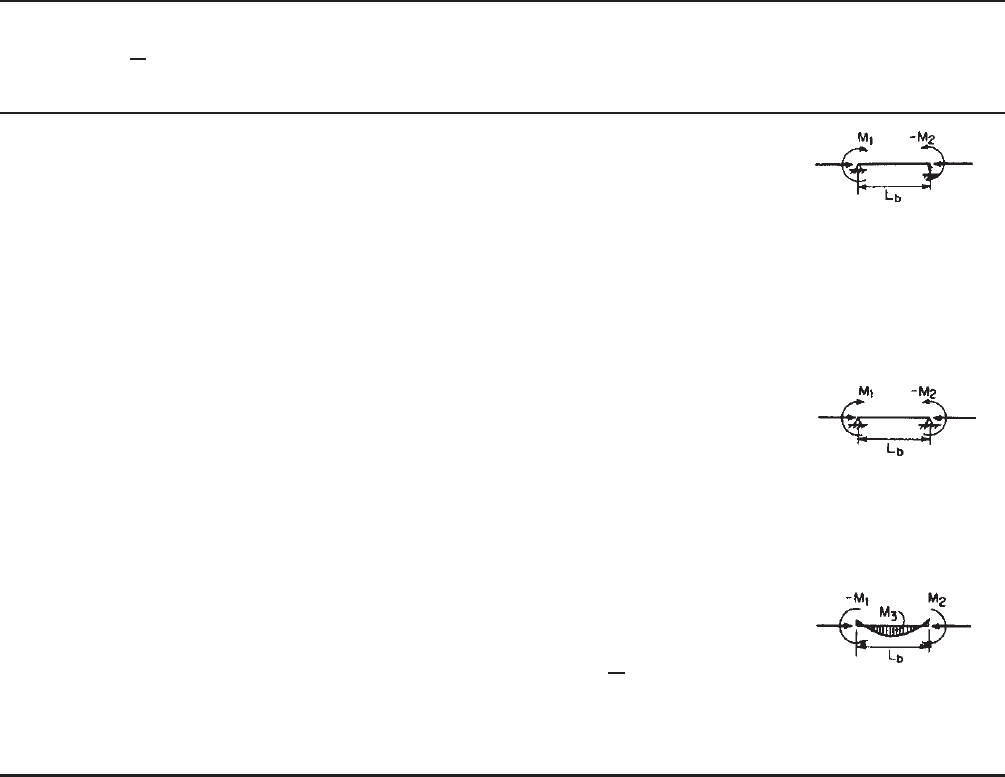
Table 6.2 Values of C
m
6.6,1.148
Loading Conditions
c
P/P
n
> 0.15 (ASD)
P/φ
c
P
n
> 0.15
Category (LRFD and LSD) M C
m
Remarks
A Computed moments
maximum at end; no
transverse loading;
joint translation not
prevented
M
2
0.85
M
1
<M
2
; M
1
/M
2
negative as s hown.
Check both Eqs. (6.53)
and (6.54) for ASD;
(6.61) and (6.62) for
LRFD and LSD
B Computed moments
maximum at end; no
transverse loading;
joint translation
prevented
M
2
0.6 − 0.4
(
±M
1
/M
2
)
Check both Eqs. (6.53)
and (6.54) for ASD;
(6.61) and (6.62) for
LRFD and LSD
C Transverse loading;
joint translation
prevented
M
2
using Eq. (6.54)
or (6.62)
1 + ψ[(
c
P)/P
E
]
(
ASD
)
a
M
2
or M
3
(whichever is
larger) using Eq. (6.53)
or (6.61)
1 + ψ(
P/P
E
) (LRFD and
LSD)
a
Check both Eqs. (6.53)
and (6.54) for ASD;
(6.61) and (6.62) for
LRFD and LSD
a
In lieu of this formula the following values of C
m
may be u sed: For members whose ends are restrained, C
m
= 0.85. For members
whose ends are unrestrained, C
m
= 1.0