Yu W., LaBoube R.A. Cold-Formed Steel Design
Подождите немного. Документ загружается.

NORTH AMERICAN DESIGN FORMULAS FOR CONCENTRICALLY LOADED COMPRESSION MEMBERS 205
4. 45
◦
≤ θ ≤ 90
◦
,
5. 2 ≤ h
o
/b
o
≤ 8, and
6. 0.04 ≤ D sin θ/b
o
≤ 0.5.
where h
o
= out-to-out web depth as defined in Fig. 3.30
b
o
= out-to-out flange width as defined in Fig. 3.48
D = out-to-out lip dimension as defined in Fig. 3.48
t = base steel thickness
θ = lip angle as defined in Fig. 3.48
The distortional buckling stress, F
d
, shall be calculated in
accordance with Eq. (5.65):
F
d
= αk
d
π
2
E
12(1 − μ
2
)
t
b
o
2
(5.65)
where α is a value that accounts for the benefit of an unbraced
length, L
m
, shorter than L
cr
but can be conservatively taken as
α =
⎧
⎪
⎨
⎪
⎩
1.0forL
m
≥ L
cr
L
m
L
cr
ln(L
m
/L
cr
)
for L
m
<L
cr
(5.66)
where L
m
is the distance between discrete restraints that restrict
distortional buckling [for continuously restrained members L
m
= L
cr
, but the restraint can be included as a rotational spring,
k
φ
, in accordance with the provi si ons in C4.2(b) or (c)],
L
cr
= 1.2h
o
b
o
D sin θ
h
o
t
0.6
≤ 10h
o
(5.67)
k
d
= 0.05 ≤ 0.1
b
o
D sin θ
h
o
t
1.4
≤ 8.0 (5.68)
E is the modulus of elasticity of steel, and μ is Poisson’s ratio.
(b) For C- and Z-Sections or Hat Sections or Any Open Section
with Stiffened Flanges of Equal Dimension Where the Stiffener
is Either a Simple Lip or a Complex Edge Stiffener. The
provisions of this section of the specification shall apply to
any open section with stiffened flanges of equal dimension,
including those meeting the geometric limits of C4.2(a):
F
d
=
k
φfe
+ k
φwe
+ k
φ
˜
k
φfg
+
˜
k
φwg
(5.69)
where k
φfe
is the elastic rotational stiffness provided by the
flange to the flange/web juncture, in accordance with Eq.
(4.116); the elastic rotational stiffness provided by the web
to the flange/web juncture is given as
k
φwe
=
Et
3
6h
o
(1 − μ
2
)
(5.70)
k
φ
is the rotational stiffness provided by restraining elements
(brace, panel, sheathing) to the flange/web juncture of a
member (zero if the flange is unrestrained) (if rotational stiff-
ness provided to the two flanges is dissimilar, the smaller
rotational stiffness is used);
˜
k
φfg
is the geometric rotational
stiffness (divided by the stress F
d
) demanded by the flange
from the flange/web juncture, in accordance with Eq. (4.118);
and the geometric rotational stiffness (divided by the stress
F
d
) d emanded by t he web from the flange/web juncture is
given as
˜
k
φwg
=
π
L
2
th
3
o
60
(5.71)
where L is the minimum of L
cr
and L
m
,
L
cr
=
6π
4
h
o
1 − μ
2
t
3
×
I
xf
(
x
o
− h
x
)
2
+ C
wf
−
I
2
xyf
I
yf
(
x
o
− h
x
)
2
1
/
4
(5.72)
and L
m
is the distance between discrete restraints that restrict
distortional buckling (for continuously restrained members L
m
= L
cr
).
See Section C3.1.4(b) in Section 4.2.4.2 of this volume for
definition of variables in Eq. (5.72).
(c) Rational Elastic Buckling Analysis. A rational elastic buck-
ling analysis that considers distortional buckling shall be
permitted to be used in lieu of the expressions given in Section
C4.2(a) or (b). The safety and resistance factors in Section C4.2
shall apply.
Additional Comments on North American Design
Formulas
In addition to the discussions of Section 5.2–5.6, the
following comments are related to some of the North Amer-
ican design provisions for concentrically loaded compres-
sion members:
1. Safety Factor. In the 1986 and earlier editions of the
AISI Specification, the allowable axial load for the ASD
method was determined by either a uniform safety factor
of 1.92 or a variable safety factor ranging from 1.67 to 1.92
for wall thickness not less than 0.09 in. (2.3 mm) and F
e
>
F
y
/2. The use of the smaller safety factors for the type of
relatively stocky columns was occasioned by their lesser
sensitivity to accidental eccentricities and the difference
in structural behavior between the c ompression members
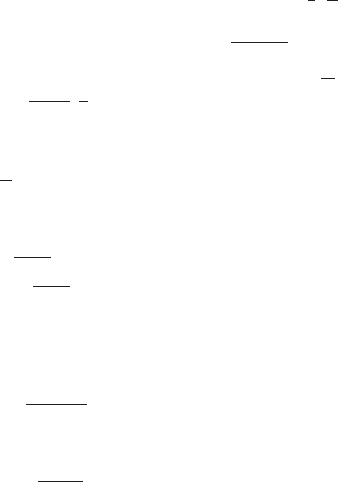
having different compactness. The latter fact is illustrated
by the stress–strain curves of the more compact and less
compact stub-column specimens, as s hown in Fig. 5.18. In
the experimental and analytical investigations conducted by
Karren, Uribe, and Winter,
2.14,2.17
both types of specimens
shown in Fig. 5.18 were so dimensioned that local buckling
would not occur at stresses below the yield stress of the
material. Test data did indicate that the less compact stub
column (curve A for cold-reduced killed press braked hat
section) reached the ultimate compressive load at strains in
the range of 3 × 10
−3
–5 × 10
–3
in./in., after which the
load dropped off suddenly because yielding was followed
by local crippling. However, the more compact stub column
206 5 COMPRESSION MEMBERS
Figure 5.18 Stress–strain curves for more compact and less
compact stub columns.
2.17
Figure 5.19 Comparison between the design axial strengths, P
d
,
for the ASD method.
(curve B for hot-rolled semi killed roll-formed channel
section) showed a long stable plateau and, after some strain
hardening, reached the ultimate load at much higher values
of strain in the range of 16 × 10
−3
–27 × 10
–3
in./in. For
this reason, the use of a smaller safety factor for more
compact sections is justified and appropriate as far as the
overall safety of the compression member is concerned.
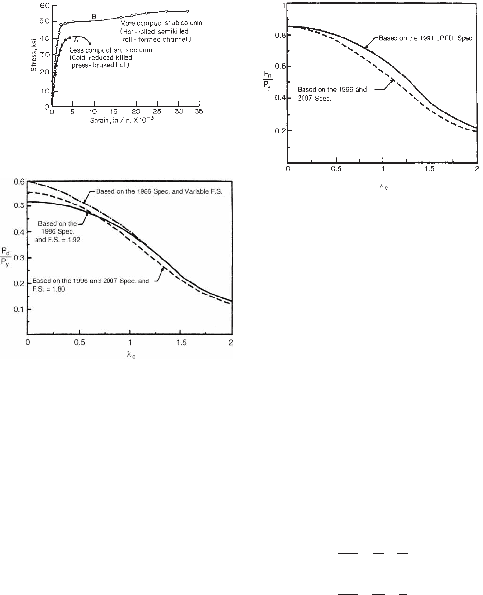
As discussed in Section 5.3.2, the AISI design equations
were changed in 1996 on the basis of a different strength
model. These equations enable the use of a single safety
factor of 1.80 for all λ
c
values. Figure 5.19 shows a
comparison of design axial strengths permitted by the 1986
and 1996 AISI Specifications and the 2007 North American
Specification. It can be seen that the design capacity is
increased by using the 1996 and 2007 Specifications for thin
columns with low slenderness parameters and decreased
for high slenderness parameters. However, the difference
would be less than 10%.
Figure 5.20 Comparison between the nominal axial strengths,
P
n
, for the LRFD method.
For the LRFD method, the differences between the
nominal axial strengths used for the 1991, 1996, and 2007
LRFD design provisions are shown in Fig. 5.20. The resis-
tance factor of φ
c
= 0.85 is the same as the 1999 AISC
Specification
3.150
and the 1991 edition of the AISI LRFD
Specification.
3.152
In the 2007 edition of the North American Specification,
the safety factor for the ASD method and the resistance
factor for the LRFD method are the same as that used in
the 1996 AISI Specification.
2. Maximum Slenderness Ratio. The maximum allow-
able slenderness ratio KL/r of compression members has
been preferably limited to 200, except that during construc-
tion the maximum KL/ r ratio should not exceed 300.
1.346
This limitation on the slenderness ratio is the same as that
used by the AISC for the design of hot-rolled heavy-steel
compression members. Even though the design formulas
are equally applicable to columns having s lenderness ratios
larger than 200, any use of the unusually long columns will
result in an uneconomical design due to the small capacity
to resist buckling. In 1999, the AISI Committee on Specifi-
cations moved the KL/r limit from the Specification to the
Commentary.
1.333
3. Flexural–Torsiona Buckling. The simplified equation
for flexural–torsional buckling [Eq. (5.58)] is based on the
following formula given by Pekoz and Winter in Ref. 5.66:
1
P
TFO
=
1
P
x
+
1
P
z
(5.73)
or
1
σ
TFO
=
1
σ
ex
+
1
σ
t
(5.74)
EFFECTIVE LENGTH FACTOR K 207
For singly symmetric angle sections with unstiffened
legs, a study conducted at the University of Sydney
by Popovic, Hancock, and Rasmussen
5.100
indicated that
the relatively compact angle section will not fail in a
flexural–torsional buckling mode if the effective area (A
e
)
under yield stress F
y
is equal to the full, unreduced cross-
sectional area (A). For this case, the concentrically loaded
angle section can be designed for flexural buckling alone
in accordance with Section C4.1.1 of the Specification.
4. Point-Symmetric Sections. As discussed in Section
5.4.3, point-symmetric sections may fail e ither in flexural
buckling about the minor principal axis or twisting. Section
C4.1.3 was added in the North American Specification
in 2001 for the design of concentrically loaded point-
symmetric reactions.
5. Design Tables. Part III of the AISI Design Manual
1.349
contains a number of design tables for column properties
and nominal axial strengths of C-sections with and without
lips including SSMA studs and tracks. The tables are
prepared for F
y
= 33, 50, and 55 ksi (228, 345, and
379 MPa, or 2320, 3515, and 3867 kg/cm
2
). In addition,
Tables III-4 to III-6 of the Design Manual provide computed
distortional buckling properties and strengths under axial
load for the representative C-shapes, SSMA studs, and Z-
shapes with lips, respectively. The values in these tables
have been calculated for use with Section C4.2(b).
5.9 EFFECTIVE LENGTH FACTOR K
In steel design, lateral bracing is generally used to resist
lateral loads, such as wind or earthquake loads, or to
increase the strength of members by preventing them from
deforming in their weakest direction.
4.111
The use of such
bracing may affect the design of compression members.
In Sections 5.3–5.8, the effective length KL of the c olumn
was used to determine buckling stresses. The factor K (a
ratio of the effective column length to the actual unbraced
length) represents the influence of restraint against rotation
and/or translation at both ends of the column.
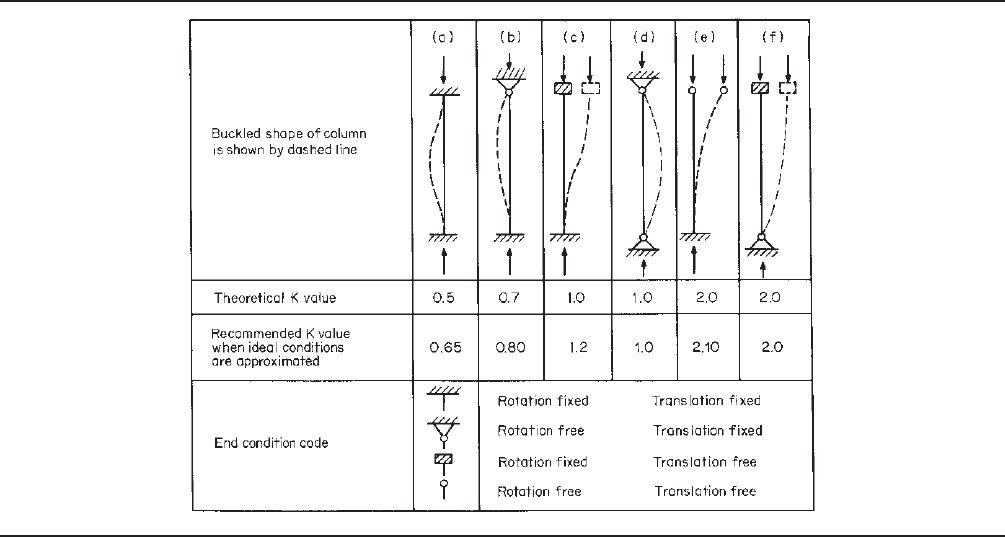
The theoretical K values and the design values recom-
mended by the Structural Stability Research Council are
tabulated in Table 5.1. In practice, the value of K = 1 can
be used for columns or studs with X-bracing, diaphragm
bracing, shear-wall construction, or any other means that
will prevent relative horizontal displacements between both
ends.
1.161
If translation is prevented and restraint against
rotation is provided at one or both ends of the member, a
value of less than 1 may be used for the effective length
factor.
In the design of trusses, it is realized that considerable
rotational restraint could be provided by continuity of the
compression chord as long as the tension members do not
yield. In view of the fact that for the ASD method tension
Table 5.1 Effective Length Factor K for Axially Loaded Columns with Various End Conditions
a
Source: Reproduced from Guide t o Stability Design Criteria for Metal Structures, 4th ed., 1988. (Courtesy of John Wiley and Sons, Inc.)
208 5 COMPRESSION MEMBERS
Figure 5.21 Laterally unbraced portal frame.
1.161
members are designed with a safety factor of 1.67 and
compression members are designed with a relatively large
safety factor of 1.80, it is likely that the tension members
will begin to yield before the buckling of compression
members. Therefore, the rotational restraint provided by
tension members may not be utilized in design as discussed
by Bleich.
3.3
For this reason, compression members in
trusses can be designed for K = 1.
1.161
However, when
sheathing is attached directly to the top flange of a contin-
uous chord, additional research has shown that the K value
may be taken as 0.75,
5.107
as discussed in Section 13.2.2.7.
Figure 5.22 Effective length factor K in laterally unbraced
portal frames.
1.161
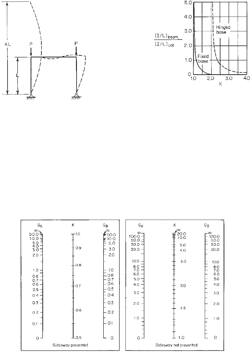
For unbraced frames, the structure depends on its own
bending stiffness for lateral stability. If a portal frame is not
externally braced in its own plane to prevent sidesway, the
effective length KL is larger than the actual unbraced length,
as shown in Fig. 5.21, that is, K > 1. This will result in
a reduction of the load-carrying capacity of columns when
the sidesway is not prevented.
For unbraced portal frames, the effective column length
can be determined from Fig. 5.22 for the specific ratio of
(I /L)
beam
/(I /L)
col
and the condition of the foundation. If
the actual footing provides a rotational restraint between
hinged and fixed bases, the K value can be obtained by
interpolation.
Figure 5.23 Alignment charts developed by L.S. Lawrence for effective length of column in
continuous frames. (Courtesy of Jackson & Moreland Division of United Engineers & Constructors,
Inc.)
1.158

BRACING OF AXIALLY LOADED COMPRESSION MEMBERS 209
The K values to be used for the design of unbraced
multistory or multibay frames can be obtained from the
alignment chart in Fig. 5.23.
1.158
In the chart, G is
defined as
G =
(
I
c
/L
c
)
(
I
b
/L
b
)
(5.75)
in which I
c
is the moment of inertia and L
c
the unbraced
length of the column and I
b
is the moment of inertia and
L
b
the unbraced length of the beam.
In practical design, when a column base is supported by
but not rigidly connected to a footing or foundation, G is
theoretically infinity, but unless actually designed as a true
friction-free pin, it may be taken as 10. If the column end
is rigidly attached to a properly designed footing, G may
be taken as 1.0.
1.158,5.67
In the use of the chart, the beam stiffness I
b
/L
b
should
be multiplied by a factor as follows when the c onditions at
the far end of the beam are known:
1. Sidesway is prevented:
1.5 for far end of beam hinged
2.0 for far end of beam fixed
2. Sidesway is not prevented:
0.5 for far end of beam hinged
0.67 for far end of beam fixed
After determining G
A
and G
B
for joints A and B at two
ends of the column section, the K value can be obtained
from the alignment chart of Fig. 5.23 by constructing a
straight line between the appropriate points on the scales
for G
A
and G
B
.
5.10 BUILT-UP COMPRESSION MEMBERS
For built-up compression members composed of two
sections in contact, the available axial strength (factored
axial resistance) shall be determined in accordance with
Section C4.1(a) of the North American Specification
(Section 5.8 in this volume) subjected to modification as
necessary. Based on Section D1.2 of the 2007 edition of
the North American specification, if the buckling mode
involves relative deformations that produce shear forces in
the connections between individual shapes, the effective
slenderness ratio KL/r is replaced by the modified effective
slenderness ratio (KL/r )
m
calculated by Eq. (5.76):
KL
r
m
=
KL
r
2
0
+
a
r
i
2
(5.76)
where (KL/r)
0
= overall slenderness ratio of entire section
about built-up member axis
a = intermediate fastener or spot weld
spacing
r
i
= minimum radius of gyration of full
unreduced cross-sectional area of an
individual shape in built-up member
See Section 5.8 for definition of other symbols. In addition,
the fastener strength (resistance) and spacing shall satisfy
the following:
1. The intermediate fastener or spot weld spacing a is
limited such that a/r
i
does not exceed one-half the
governing slenderness ratio of the built-up member.
2. The ends of a built-up compression member are
connected by a weld having a length not less than
the maximum width of the member or by connectors
spaced longitudinally not more than four diameters
apart for a distance equal to 1.5 times the maximum
width of the member.
3. The intermediate fastener(s) or weld(s) at any longi-
tudinal member tie location are capable of transmit-
ting a force in any direction of 2.5% of the nominal
axial strength (compressive resistance) of the built-up
member.
In the above design criteria, Eq.(5.76) was added to the
North American Specification since 2001 on the basis of the
1999 AISC Specification and the 1994 CSA Standard.
1.117
The overall slenderness ratio, (KL/r)
0
, is computed about
the same axis as the modified slenderness ratio, (KL/r)
m
.
The (KL/r)
m
ratio replaces KL/r for both flexural and
flexural–torsional buckling.
Section D1.2 of the North American Specification
includes the above three requirements concerning interme-
diate fastener spacing a, end connection of the built-up
member, and the applied force for the design of inter-
mediate fastener(s). The intermediate fastener spacing
requirement (1) for [a/r
i
≤ 0.5(KL/r)] is to prevent
flexural buckling of individual shapes between interme-
diate connectors to account for any one of the connectors
becoming loose or ineffective. Requirements 2 and 3 are
related to connection design as discussed in Section 8.8
and illustrated in Example 8.6.
For the research work on built-up compression
members, recent studies have been made by Yang and
Hancock,
5.188,5.191
Brueggen and Ramseyer,
5.189
Stone and
LaBoube,
5.190
Young and Chen,
5.192
and others.
5.11 BRACING OF AXIALLY LOADED
COMPRESSION MEMBERS
In the 2007 edition of the North American Specification,
new design provisions are included for bracing of axially
loaded compression members. According to Section D3.3
210 5 COMPRESSION MEMBERS
of the Specification, the required brace strength (resistance)
and brace stiffness to restrain lateral translation at a brace
point for an individual compression member shall be calcu-
lated by Eqs. (5.77) and (5.78), respectively, as follows:
P
br,1
= 0.01P
n
(5.77)
for required brace strength,
β
br,1
=
2[4 − (2/n)]P
n
L
b
(5.78)
for required brace stiffness
where P
br,1
= required nominal brace strength (resistance)
for a single compression member
P
n
= required axial compression strength
(resistance) for a single compression
member
β
br,1
= required brace stiffness for a single
compression member
n = number of equally spaced intermediate
brace locations
L
b
= distance between braces on one
compression member
The above design requirements were developed from a
study conducted by Green, Sputo, and Urala in 2004.
5.193
These provisions for lateral translation assume that the
braces are perpendicular to the compression member being
braced and located in the plane of buckling. The stiff-
ness requirements include the contributions of the bracing
members, connections, and anchorage details.
1.346
It should
be noted that these requirements are only for lateral trans-
lation of the compression member.They do not account
for torsion or flexural–torsional buckling, which may be
designed through rational analysis or other methods. Addi-
tional design information on bracing can be found from
the publications of Helwig and Yura,
5.194
Green, Sputo,
and Urala,
5.195
Sputo and Turner,
5.196
Sputo and Beery,
5.197
Tovar, Helwig, and Sputo,
5.207
and others.
5.12 DESIGN EXAMPLES
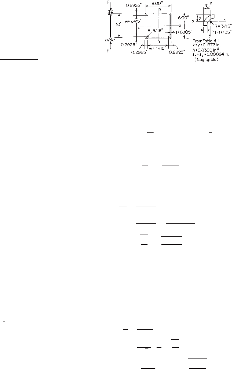
Example 5.1 Determine the allowable axial load for
the square tubular column shown in Fig. 5.24. Assume
that F
y
= 40 ksi, K
x
L
x
= K
y
L
y
= 10 ft, and the dead
load–live load ratio is
1
5
.UsetheASDandLRFD
methods.
SOLUTION
A. ASD Method
Since the square tube is a doubly symmetric closed section,
it will not be subject to torsional or flexural–torsional
buckling. It can be designed for flexural buckling.
Figure 5.24 Example 5.1.
1. Sectional Properties of Full Section
w = 8.00 − 2(R + t) = 7.415 in.
A = 4(7.415 × 0.105 + 0.0396) = 3.273 in.
2
I
x
= I
y
= 2(0.105)
1
12
(7.415)
3
+ 7.415
4 −
1
2
× 0.105
2
+ 4(0.0396)(4.0 −0.1373)
2
= 33.763 in.
4
r
x
= r
y
=
I
x
A
=
33.763
3.273
= 3.212 in.
2. Nominal Buckling Stress F
n
. According to Eq. (5.56),
the elastic flexural buckling stress F
e
is computed as
follows:
KL
r
=
10 × 12
3.212
= 37.36 < 200 OK
F
e
=
π
2
E
(KL/r)
2
=
π
2
(
29,500
)
(
37.36
)
2
= 208.597 ksi
λ
c
=
F
y
F
e
=
40
208.597
= 0.438 < 1.5
F
n
=
0.658
λ
2
c
F
y
=
0.658
0.438
2
40
= 36.914 ksi
3. Effective Area A
e
. Because the given square tube
is composed of four stiffened elements, the effec-
tive width of stiffened elements subjected to
uniform compression can be computed from Eqs.
(3.41)–(3.44):
w
t
=
7.415
0.105
= 70.619
λ =
1.052
√
k
w
t
F
n
E
λ =
1.052
√
4
(
70.619
)
36.914
29,500
= 1.314
DESIGN EXAMPLES 211
Since λ>0.673, from Eq. (3.42),
b = ρw
where
ρ =
1 − 0.22/λ
λ
=
1 − 0.22/1.314
1.314
= 0.634
Therefore,
b = (0.634)(7.415) = 4.701 in.
Theeffectiveareais
A
e
= 3.273 − 4(7.415 − 4.701)(0.105)
= 2.133 in.
2
4. Nominal and Allowable Loads. Using Eq. (5.53), the
nominal load is
P
n
= A
e
F
n
= (2.133)(36.914) = 78.738 kips
Theallowableloadis
P
a
=
P
n
c
=
78.738
1.80
= 43.74 kips
B. LRFD Method
In item A above, the nominal axial load P
n
was computed
to be 78.738 kips. The design axial load for the LRFD
method is
φ
c
P
n
= 0.85(78.738) = 66.93 kips
Based on the load combination of dead and live loads, the
required load is
P
u
= 1.2P
D
+ 1.6P
L
= 1.2P
D
+ 1.6(5P
D
) = 9.2P
D
where P
D
= axial load due to dead load
P
L
= axial load due to live load
By using P
u
= φ
c
P
n
, the values of P
D
and P
L
are
computed as follows:
P
D
=
66.93
9.2
= 7.28 kips
P
L
= 5P
D
= 36.40 kips
Therefore, the allowable axial load is
P
a
= P
D
+ P
L
= 43.68 kips
It can be seen that the allowable axial loads determined
by the ASD and LRFD methods are practically the same.
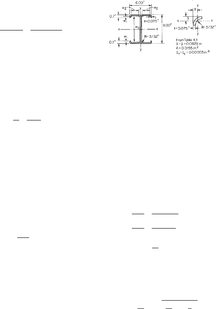
Example 5.2 Use the ASD and LRFD methods to deter-
mine the available strengths of the I-section (Fig. 5.25) to be
used as a compression member. Assume that the effective
length factor K is 1.0 for the x and y axes and that the
Figure 5.25 Example 5.2.
unbraced lengths for the x and y axes are 12 and 6 ft,
respectively. Also assume that K
t
L
t
= 6ft.UseF
y
= 33 ksi.
The intermediate fastener spacing is assumed to be 12 in.
SOLUTION
A. ASD Method
1. Properties of Full Section. Based on the method used
in Chapter 4, the following full section properties can be
computed:
A = 2.24 in.
2
I
x
= 22.1in.
4
I
y
= 4.20 in.
4
r
x
= 3.15 in. r
y
= 1.37 in.
2. Nominal Buckling Stress, F
n
. Since the given I-section
is a doubly symmetric section, the nominal buckling stress
will be governed by either flexural buckling or torsional
buckling as discussed in Section 5.4.1.
a. Elastic Flexural Buckling. By using Eq. (5.56), the
elastic flexural buckling stress can be computed as
follows:
K
x
L
x
r
x
=
(1)(12 × 12)
3.15
= 45.714
K
y
L
y
r
y
=
(1)(6 × 12)
1.37
= 52.555
Use
KL
r
= 52.555
Since the slenderness ratio KL/r is governed by the
column buckling about the y axis of the I-section, which
involves relative deformations that produce shear forces
in the connections between individual channels, the
modified slenderness ratio (KL/r )
m
should be used to
compute the elastic flexural buckling s tress F
e
. Based
on Eq. (5.76),
KL
r
m
=
KL
r
2
0
+
a
r
i
2
212 5 COMPRESSION MEMBERS
where (KL/r)
0
= 52.555
a = intermediate fastener spacing,
=12 in.
r
i
= radius of gyration of a channel
section about its y axis, =1.08 in.
Therefore,
KL
r
m
=
(52.555)
2
+
12
1.08
2
= 53.717
Since a/r
i
< 0.5(KL/r)
m
, requirement 1 of Section 5.10
is satisfied,
F
e
=
π
2
E
(KL/r)
2
m
=
π
2
(29,500)
(53.717)
2
= 100.902
b. Elastic Torsional Buckling. Using Eq. (5.22) of Section
5.4.1, the torsional buckling stress is
F
e
= σ
t
=
1
Ar
2
0
GJ +
π
2
EC
w
(
K
t
L
t
)
2
where A = 2.24 in.
2
r
0
=
r
2
x
+ r
2
y
=
(
3.15
)
2
+
(
1.37
)
2
= 3.435 in.
G = 11,300 ksi
J = 0.00418 in.
4
C
w
= 70.70 in.
6
E = 29,500 ksi
K
t
L
t
= 6ft
Therefore
F
e
= σ
t
=
1
(
2.24
)(
3.435
)
2
(
11,300
)(
0.00418
)
+
π
2
(
29,500
)(
70.70
)
(
6 × 12
)
2
= 152.02 ksi
The nominal buckling stress F
n
is determined by using
the smaller value of the elastic flexural buckling stress
and torsional buckling stress, that is,
F
e
= 100.902 ksi
λ
c
=
F
y
F
e
=
33
100.902
= 0.572 < 1.5
From Eq. (5.54),
F
n
= (0.658
λ
2
c
)F
y
= (0.658
0.572
2
)(33) = 28.777 ksi
3. Effective Area A
e
at Stress, F
n
w
1
= 0.7 − (R + t) = 0.5313 in.
w
2
= 3.0 − 2(R + t) = 2.6625 in
w
3
= 8.0 − 2(R + t) = 7.6625 in.
a. Effective Width of the Compression Flanges (Section
3.5.3.1). From Eq. (3.80),
S = 1.28
E
f
= 1.28
29,500
28.777
= 40.982
0.328S = 13.442
w
2
t
=
2.6625
0.075
= 35.50
Since w
2
/t > 0.328S , use Eq. (3.81) to compute the
required moment of inertia of the e dge stiffener I
a
as
follows:
I
a
= 399t
4
w
2
/t
S
− 0.328
3
= 399(0.075)
4
35.50
40.982
− 0.328
3
= 0.002 in.
4
The above computed value should not exceed the
following value:
I
a
= t
4
115(w
2
/t)
S
+ 5
= (0.075)
4
115(35.50)
40.982
+ 5
= 0.0033 in.
4
Therefore, use I
a
= 0.002 in.
4
For the simple lip edge
stiffener,
D = 0.7in. d = 0.5313 in.
d
t
=
0.5313
0.075
= 7.08
By using Eq. (3.83), the moment of inertia of the full
edge stiffener is
I
s
=
d
3
t
12
=
(w
1
)
3
t
12
=
(0.5313)
3
(0.075)
12
= 0.000937 in.
4
From Eq. (3.82),
R
I
=
I
s
I
a
=
0.000937
0.0020
= 0.469 < 1.0OK
The effective width b of the compression flange can be
calculated as follows:
D
w
2
=
0.7
2.6625
= 0.263
From Eq. (3.84),
n = 0.582 −
w
2
/t
4S
= 0.582 −
35.50
4 × 40.982
= 0.365 >
1
3

DESIGN EXAMPLES 213
Use n = 0.365. Since 0.25 < D/ w
2
< 0.8 and θ = 90
◦
,
k =
4.82 −
5D
w
2
(R
I
)
n
+ 0.43
= [4.82 − 5(0.263)](0.469)
0.365
+ 0.43 = 3.09 < 4.0
Use k = 3.09 to compute the effective width of the
compression flange.
From Eqs. (3.41)–(3.44),
λ =
1.052
√
k
w
2
t
f
E
=
1.052
√
3.09
(35.50)
28.777
29,500
= 0.664 < 0.673
ρ = 1.0
b = w
2
= 2.6625 in.
b. Effective Width of Edge Stiffeners
w
1
t
=
0.5313
0.075
= 7.084
λ =
1.052
√
k
w
1
t
f
E
=
1.052
√
0.43
(7.084)
28.777
29,500
= 0.355 < 0.673
d
s
= w
1
= 0.5313 in.
Based on Eq. (3.79), the reduced effective width of the
edge stiffener is
d
s
= R
I
d
s
= (0.469)(0.5313) = 0.249 in. <d
s
OK
c. Effective Width of Web Elements
w
3
t
=
7.6625
0.075
= 102.167 < 500 OK
λ =
1.052
√
k
w
3
t
f
E
=
1.052
√
4
(102.167)
28.777
29,500
= 1.678 > 0.673
ρ = 1 −
0.22/λ
λ
= 1 −
0.22/1.678
1.678
= 0.518
b = ρw
3
= (0.518)(7.6625) = 3.969 in.
d. Effective Area A
e
A
e
= 2.24 − [4(0.5313 − 0.249)
+ 2(7.6625 − 3.969)](0.075)
= 2.24 − 0.639 = 1.601 in.
2
4. Nominal Axial Load for Flexural Buckling. The
nominal load is
P
n
= A
e
F
n
= (1.601)(28.777) = 46.07 kips
5. Distortional Buckling Strength. Because edge-
stiffened flanges are used for the I-section, the nominal
axial load for distortional buckling should be checked
according to Section C4.2 of the North American
Specification as provided here in Section 5.8.
I. Application of Section C4.2(a) of the Specification. At
the present time (2009), the AISI Committee intends
to move Section C4.2(a) of the Specification to the
Commentary because it is just for preliminary design
and has been specifically derived to always be more
conservative than Section C4.2(b). However, the
following calculations are included for the purpose of
comparison:
a. Yield load P
y
: Based on Eq. (5.63),
P
y
= A
g
F
y
= (2.24)(33) = 73.92 kips
b. Distortional Buckling Load P
crd
: From Eq. (5.64),
P
crd
= A
g
F
d
in which, the elastic distortional buckling stress F
d
is calculated in accordance with Section C4.2(a) of
the North American Specification. In order to use
Eq. (5.65) to compute F
d
, the following geometric
limits should be satisfied:
i. 50 <(h
o
/t = 106.67)<200 OK
ii. 25 <(b
o
/t = 40)<100 OK
iii. 6.25 <(D/t= 9.33)<50 OK
iv. 45
◦
<(θ= 90
◦
) = 90
◦
OK
v. 2 <(h
o
/b
o
= 2.67)<8OK
vi. 0.04 <(Dsin θ/b
o
= 0.23)<0.5OK
From Eq. (5.65), the elastic distortional buckling stress
is calculated as follows:
F
d
= αk
d
π
2
E
12(1 − μ
2
)
t
b
o
2
From Eq. (5.67), the distortional buckling half-
wavelength L
cr
is
L
cr
= 12h
o
b
o
D sin θ
h
o
t
0.6
≤ 10h
o
= 12(8.00)
3.00 × 0.7 × sin 90
◦
8.00 × 0.075
0.6
≤ 10(8.00)
= 20.36 in. ≤ 80.00 in.
Use L
cr
= 20.36 in. Since (L
m
= L
y
= 72 in.) > L
cr
, α
= 1.0.
214 5 COMPRESSION MEMBERS
Based on Eq. (5.68), the plate buckling coefficient k
d
for distortional buckling is
k
d
= 0.1
b
o
D sin θ
h
o
t
1.4
= 0.1
3.00 × 0.7 × sin 90
◦
8.00 × 0.075
1.4
= 0.578
Since 0.05 <k
d
< 8.00, use k
d
= 0.578. The elastic
distortional buckling stress F
d
is
F
d
= (1)(0.578)
π
2
(29,500)
12(1 − 0.3
2
)
0.075
3.00
2
= 9.63 ksi
Therefore,
P
crd
= A
g
F
d
= 2.24(9.63) = 21.57 kips
Based on Eq. (5.62),
λ
d
=
P
y
P
crd
=
73.92
21.57
= 1.85 > 0.561
From Eq. (5.61), the nominal axial load for distortional
buckling based on Section C4.2(a) is
P
n
=
1 − 0.25
P
crd
P
y
0.6
P
crd
P
y
0.6
P
y
=
1 − 0.25
21.57
73.92
0.6
21.57
73.92
0.6
(73.92)
= 31.09 kips
II. Application of Section C4.2(b) of the Specification.
Based on the equations listed in Table 4.4, the geometric
flange properties for the C-section used for the given
I-section can be computed as follows. The reason
for the following calculations is that the mechanical
model for prediction of distortional buckling strength
considers the flange itself as a “column” which may
undergo restrained flexural–torsional buckling, and the
restraint comes from the web and additional attach-
ments. It should be noted that in the equations below the
symbols x
0
and y
0
are presented as x
0f
and y
0f
, respec-
tively, to prevent confusion with other sections of the
specification.
h = h
o
− t = 8.000 − 0.075 = 7.925 in.
b = b − t = 3.000 − 0.075 = 2.925 in.
d = D −
1
2
t = 0.700 −
1
2
× 0.075 = 0.6625 in.
A
f
= (b + d)t = (2.925 +0.6625)(0.075)
= 0.269 in.
2
I
xf
= t[t
2
b
2
+ 4bd
3
+ t
2
bd + d
4
]/12(b + d)
= (0.075)[(0.075)
2
(2.925)
2
+ 4(2.925)(0.6625)
3
+ (0.075)
2
(2.925)(0.6625)
+ (0.6625)
4
]/12(2.925 + 0.6625)
= 0.00637 in.
4
I
yf
= t[b
4
+ 4db
3
]/12(b + d)
= (0.075)[(2.925)
4
+ 4(0.6625)(2.925)
3
]/
12(2.925 + 0.6625)
= 0.243 in.
4
I
xyf
= tb
2
d
2
/4(b + d)
= (0.075)(2.925)
2
(0.6625)
2
/4(2.925 + 0.6625)
= 0.0196 in.
4
x
of
= b
2
/2(b + d) = (2.925)
2
/2(2.925 + 0.6625)
= 1.192 in.
y
of
=−d
2
/2(b + d)
=−(0.6625)
2
/2(2.925 + 0.6625)
=−0.0612 in.
h
x
=−[b
2
+ 2db]/2(b + d)
=−[(2.925)
2
+ 2(0.6625)(2.925)]/
2(2.925 + 0.6625)
=−1.733 in.
J
f
= [bt
3
+ dt
3
]/3
= [(2.925)(0.075)
3
+ (0.6625)(0.075)
3
]/3
= 0.000504 in.
4
C
wf
= 0.0in.
6