ASM Metals HandBook Vol. 14 - Forming and Forging
Подождите немного. Документ загружается.

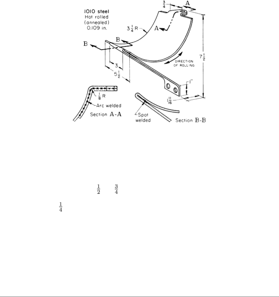
Fig. 3 Severely bent fuel tank bracket th
at was protected against fatigue failure by bending across the grain
and by local reinforcement. Dimensions given in inches.
Because of offsets in the developed blanks, they could be nested slightly by reversing every other one in stock layout. The
production procedure was as follows:
• Shear blank 267 × 451 mm (10 × 17 in.)
• Blank and pierce two parts from sheared blank
• Form 83 mm (3 in.) radius and 25 mm (1 in.) flange
• Bend 75 mm (3 in.) leg down 90°
• Flatten 75 mm (3 in.) leg
• Spot weld 75 mm (3 in.) leg
• Arc weld reinforcing strip
An 890 kN (100 tonf) single-action mechanical press was used for the second, third, and fourth operations listed above;
the fifth operation was done in a press brake. Single-operation dies were used for all operations. Blanking tools were of
D2 tool steel; bending tools were of O1 tool steel with a ground finish. Life of the tools before regrind was 50,000 pieces.
Mineral oil was the lubricant. The production lots were about 2500 pieces, and annual production was approximately
10,000 pieces.
Press Bending of Low-Carbon Steel
Die Construction
The same types of bending dies as those used in press brakes can generally be used in presses. However, there are major
differences, as follows.
First, because presses ordinarily are not long and narrow like press brakes, more consideration must be given to clearance
for removing the finished workpiece when the press is open, as well as clearance for the legs of the bend when the piece
is being formed. The bed dimensions of a press also limit the size of workpiece that can be bent.
Second, presses cycle rapidly, and shut height is not as easy to change; therefore, fewer pieces are bent in air, as described
in the article "Press-Brake Forming" in this Volume. More frequently, pieces are formed by bottoming the dies. This has
the advantage of decreasing springback.
Lastly, presses are usually used for workpieces less than 610 mm (2 ft) long, and press brakes for pieces longer than 610
mm (2 ft). However, the automotive industry bends very large sheet metal structural members on large presses by mass-
production methods.
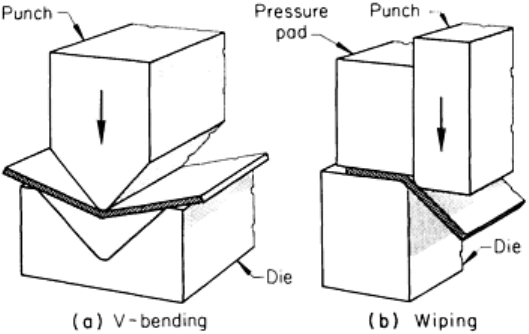
V-dies are composed of a V-block for a die and a wedge-shaped punch (Fig. 4a). The width of the opening in the V is
ordinarily at least eight times the stock thickness. In bending, the workpiece is laid over the V in the die, and the punch
descends to press the workpiece into the V to form the bend.
The included angle of a V-bend can be changed by
adjusting the distance that the punch forces the sheet
metal into the V-die. When the piece must be
overbent (to allow for springback), the angle of the
punch is smaller than the included angle on the part.
Bottoming the punch and striking the metal severely
at the bend is a means of reducing springback.
In V-die bending of a flange along the edge of a
wide sheet, distortion is likely to occur. Most of the
sheet overhangs the die and lifts up as bending takes
place. If the punch strikes too fast, the workpiece
will distort and will have irregular break lines.
However, if the press ram is slowed down just
before the punch hits the work, distortion is
minimized.
For this type of V-die work, presses are available in
which the ram advances rapidly, slows down just
above the work, proceeds slowly through the bottom
of the stroke, and returns rapidly. In addition, there
are presses in which the rate of ram advance can be controlled somewhat by the operator.
Wiping Dies. Another type of bending die is the wiping die (Fig. 4b). A pressure pad that is either spring loaded or
attached to a fluid cylinder clamps the workpiece to the die before the punch makes contact. The punch descends and
wipes one side of the workpiece over the edge of the die. The bend radius is on the edge of the die. To prevent the wiping
action from being too severe, there may be a radius or chamfer on the mating face of the punch. When springback must be
compensated for, the die is undercut to permit overbending. The flange metal can be put in slight tension by ironing it
between the punch and the die. Sharp bends generally cannot be made in one operation in a wiping die without cracking
the metal, because a punch or die with a sharp edge will cut the metal rather than bend it.
Interchangeable V-Dies. Figure 5 shows equipment for making various sizes of V-bends in a punch press. Four
different sizes of punches can be mounted into the punch holder, which is attached to the press slide. In operation, the
groove in the die that gives the needed bend is aligned with the punch, and the die is then fastened to the bolster plate on
the press bed. Adjustable side and end stops can be used to position the blanks for bending.
Fig. 4 Bending in a V-
die (a) and a wiping die (b). The
wiping die can be of inverted design. The workpiece would
move downward by the action of the punch aga
inst the
pressure pad, and the flange would bend upward.
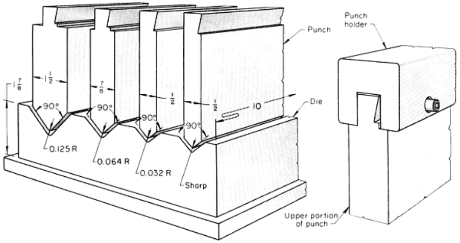
Fig. 5 V-bending punch and die for making a variety of bends in a punch press. Dimensions given in inches.
With equipment such as that illustrated in Fig. 5, rectangular boxes in a range of shapes and sizes are often produced more
economically by bending flat blanks into folded-end shapes than by deep drawing. Making folded-end pans by bending in
adjustable wing dies and cam dies with interchangeable punches is described in the article "Press Forming of Coated
Steel" in this Volume.
U-Bending Dies. U-shaped pieces can be bent in a die such as the one shown in Fig. 6. The width of the U is adjustable
by means of spacers and by changing the width of the knockout. Punches can be mounted in the press with a holder
similar to that shown in Fig. 5 and can be provided to the proper width and shape to make either a U or a channel shape.
Side clearance should be 10% more than stock thickness.
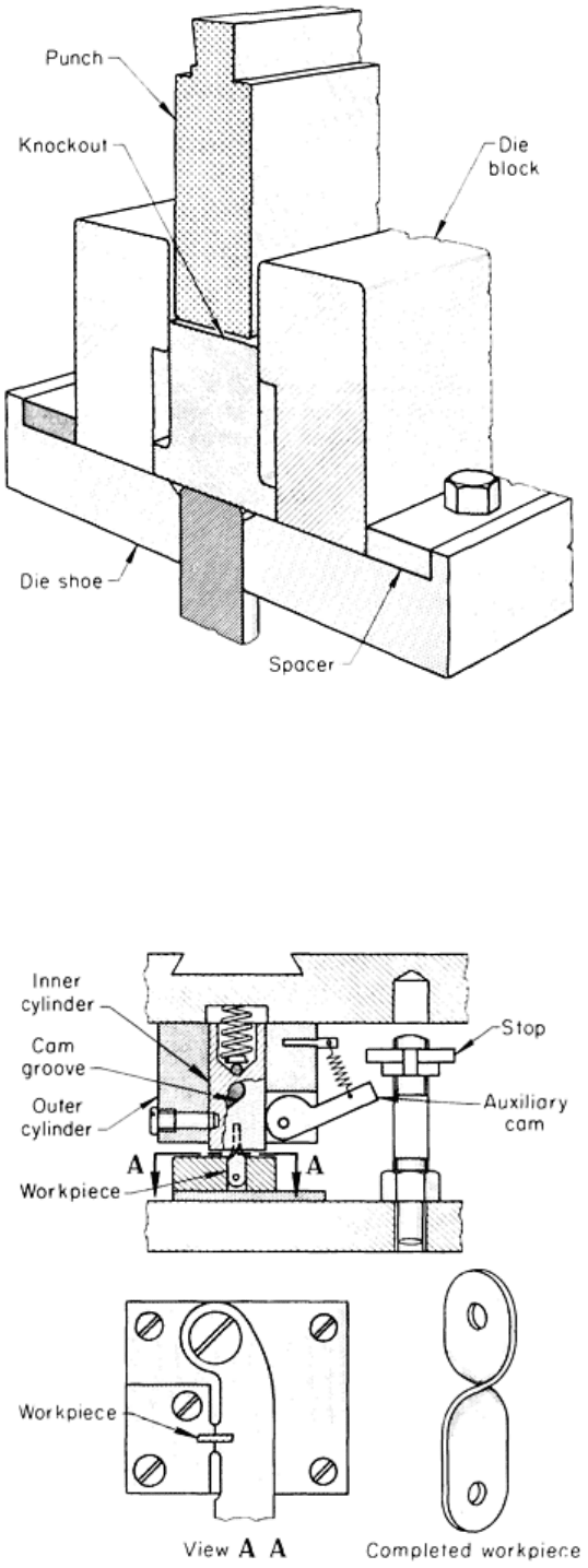
Fig. 6 Adjustable U-bending die for use in a punch press.
Rotary-bending dies (Fig. 7) are used to make bends or twists in bars or strip. These dies use cam action to rotate the
workpiece.
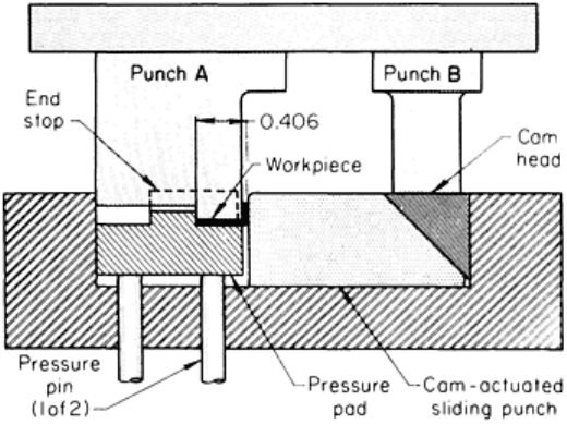
Fig. 7 Rotary-bending die used for 90° twisting of strip metal. Die is shown in close
d position; inner cylinder
has rotated to give workpiece a 90° twist. The auxiliary cam prevents rotation of the inner cylinder until it is
free of workpiece.
As shown in Fig. 7, a 90° twist is given to strip metal to make a connecting link. The punch is made in two major parts: a
hollow cylinder that is solidly mounted to the ram, and inside it a solid cylinder that is free to rotate. The inner cylinder
has a 90° helical cam groove in its cylindrical surface that engages a hardened pin in the outer cylinder.
When the ram descends, a slot in the face of the inner cylinder engages the end of the workpiece. After the inner cylinder
bottoms, as the ram continues to move down, the spring compresses, letting the outer cylinder move down over the inner
cylinder. The action of the pin in the groove makes the inner cylinder rotate, giving the workpiece a 90° twist.
An auxiliary cam keeps the inner cylinder from rotating back in the return stroke, until it has cleared the workpiece. Near
the top of the stroke, the auxiliary cam is released by a stop, allowing the inner cylinder to return to its starting position.
Cam-Actuated Flanging Dies. Horizontal motion is often needed to form, or partially form, a flange on a workpiece.
One of the most commonly used methods of producing this motion at right angles to the motion of the main press ram is
with an inclined surface, or cam, in the die mechanism.
As shown in Fig. 8, a blankholder contacts the work first and holds it in position. Resiliency, either in the form of
pressure pins leading to a die cushion or in the form of a spring, allows the ram to continue to descend. A cam actuates
the sliding punch, which either forms or completes the forming of the flange and is then retracted. The blank is placed on
the pressure pad, where it is held by punch A and wiped past the cam-actuated sliding punch to form the flange. Near the
bottom of the stroke, punch B contacts the cam head, which moves the sliding punch to set the flange to the 10.3 mm
(0.406 in.) dimension and a 90° angle. Cam-actuated sliding punches on each side of the forming punch can be used for
setting flanges on channel and U-shape parts.
Cam-actuated dies are often used in combination with
other tooling to produce complicated parts. When used
in tandem with a progressive die, a cam-actuated die
can significantly reduce the number of operations
needed to produce a part. A drawer front that
originally required nine separate operations (two
shearing, two notching, one piercing, one box-
forming, and three flanging) when using a press brake
was produced in only four separate operations (slitting
coil to width; notching, piercing, and cutting off in a
progressive die; box-forming in a second die; and
flanging the sides, top, and bottom in a cam-actuated
flanging die) with the incorporation of a cam-actuated
die.
Compound Flanging and Hemming Die. The
compound flanging and hemming die shown in Fig. 9
is unusual in having no horizontal motion of punches
or dies. There are two cushions: a spring-loaded hold-
down plate and an air cushion for the die plate. As the
ram descends, the hold-down makes first contact,
clamping the piece securely to the die. As the ram
continues to descend, the springs compress, and the
angled flange is formed between the angled face of the bending punch and the die plate.
Fig. 8 Cam-
actuated single flanging die used for producing
a multiflanged part. See text for description of operation.
Dimensions given in inches.
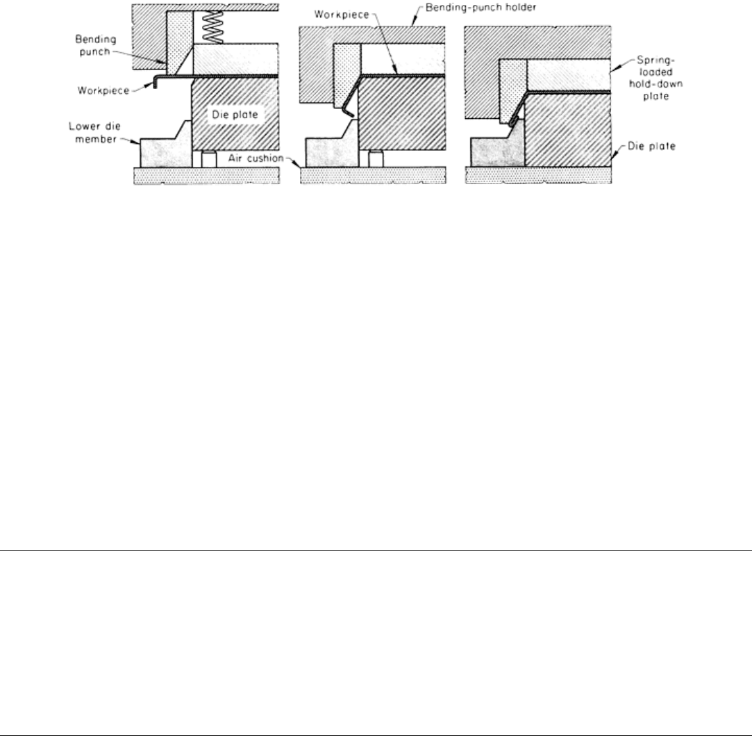
Fig. 9 Compound flanging and hemming die without horizontal motion.
The angle of the bend is set and slightly coined between the chamfer on the edge of the die plate and the angled face of
the punch. At this point, the hold-down plate bottoms against the bending-punch holder, then the air cushion begins to
yield, lowering the die plate. The edge of the workpiece bumps the corner of the lower die member and folds up into a
hem that is completed between the angled face of the bending punch and the mating face of the lower die member.
Wing Dies. Special dies for making U-shape bends have wings that turn up on each side as the punch descends. These
dies are described in the article "Bending and Forming of Tubing" in this Volume.
Die Materials. Simple bending dies are ordinarily subjected to less shock than other press-working tools; therefore, they
can often be made of low-carbon steel, heat-treated low-alloy steel such as 4140, or cast iron for low production of low-
carbon steel pieces. For moderately high production, they should be made of flame-hardening grades of carbon steel, such
as 1045, or flame-hardening cast iron, such as class 40 gray iron. Cam-operated dies, wiping dies, and dies used to make
curved flanges (shrink or stretch) must be made of a higher grade of material. Tool steels such as O1 or A2 are used for
moderately long production runs. For a total tool life of 1 million or more pieces, D2 tool steel is used.
Press Bending of Low-Carbon Steel
Single-Operation Dies
Single-operation dies are used for low production or on pieces that are so difficult to bend that only one operation at a
time is feasible. Some single-operation dies are general-purpose dies that can make bends in simple workpieces of many
different designs. Others are single-purpose dies for a particular piece.
Press Bending of Low-Carbon Steel
Use of Compound Dies
In a compound die, two or more operations are combined at a single work station without relocating the workpiece in the
die, so that a finished piece is produced with each stroke of the press. One or more of the operations done in the die can be
bending. The press speed (strokes per minute) for compound dies is generally only slightly lower than for single-
operation dies; therefore, production time and labor cost per piece are decreased almost in proportion to the number of
operations done in the compound die.
In most applications, the cost of a compound die does not differ greatly from the combined cost for equivalent separate
dies, and is sometimes less. Operations must be judiciously combined in making a compound die in order not to have die
sections that are too thin to be heat treated without distortion, or that will break down under the cyclic loading of ordinary
die operation. If these precautions are observed, die life and die maintenance costs should be nearly the same as the costs
for equivalent simple dies. Compound dies can be fed individual blanks, or they can be fed strip stock, as in the following
example.
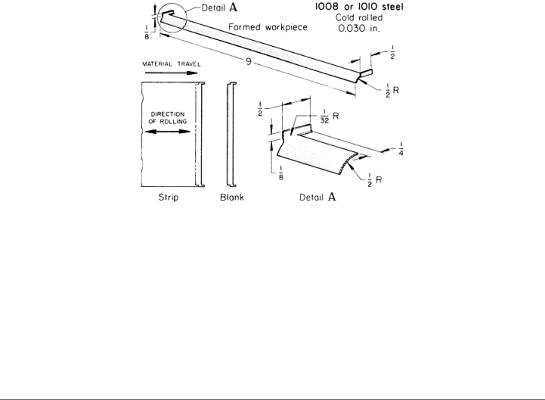
Example 3: Use of a Compound Die for Production of Blower Blades from Strip
Stock.
Blower blades, shaped as shown in Fig. 10, were cut off from strip stock and bent in a compound die in a 530 kN (60
tonf) mechanical press. The blades were made of 0.76 mm (0.030 in.) thick cold-rolled commercial-quality 1008 or 1010
steel, either plain or galvanized. Some aluminum blades were also made in the same die.
Fig. 10 Blower blade that was blanked and formed from strip stock in a compound die.
Dimensions given in
inches.
As shown in Fig. 10, the leading edge of one blade was made with the same cut as the trailing edge of the next. The bend
axis of the flanges was parallel with the rolling direction of the metal, and the curvature on the surface of the blade behind
the flanges was formed across the rolling direction.
The die material was W2 or A5 tool steel. For both materials, die life between regrinds was 1 million pieces. A 1:5
mixture of soluble oil and water was used as a lubricant because a wiping action was used in bending the flanges. The
production rate was 1600 pieces per hour, and the annual production was 150,000 pieces. The flanges at the ends of each
blade were used for attaching the blades at assembly.
Press Bending of Low-Carbon Steel
Use of Progressive Dies
Progressive dies are similar in function to compound dies in that they combine in one die set several operations that are
performed with one stroke of the press. In a progressive die, however, the operations are separated and distributed among
a number of stations. The stock progresses through these stations in the strip form until the finished workpiece is cut from
the strip at the last station. Consequently, at the start of a strip, there are several press strokes before a piece is produced.
Thereafter, a finished workpiece is produced with each stroke of the press, up to the end of the strip.
If the strips are short, sheared from sheets, they can be fed into the die so that each strip is butted against the end of the
preceding strip for continuous production. Otherwise, starting stops are used for each new strip.
Coil stock is fed into the die at one end. A hole or notch is usually made in the strip at the first station, and subsequent
stations use this as a pilot to keep the strip properly aligned and positioned while the operations are performed. When the
workpiece is complete, it is cut from the strip, which has acted as a holder to carry the piece from station to station.
Intricate pieces, often needing no further work, can be made in one press.
In planning the strip layout for progressive-die operations, consideration must be given to development of the part outline,
to provision for piloting, to distribution of press load and strength of die elements, and to ensuring minimum metal waste.
Some compromise among these factors is usually necessary in developing a sequence of operations and designing a
progressive die to accomplish these operations. The strip layout in the following example used the metal efficiently by
having the developed flanges surround the body of the preceding part.
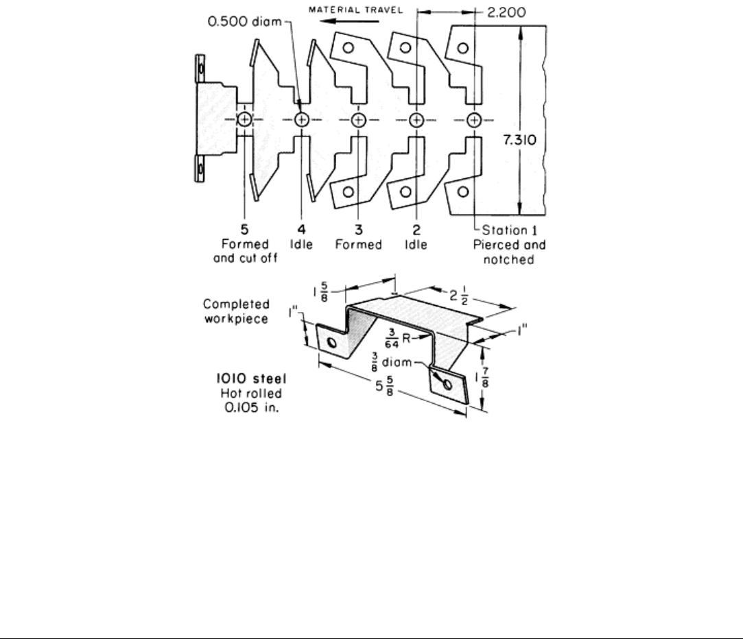
Example 4: Nesting of Workpieces to Minimize Stock Waste.
The bracket shown in the lower part of Fig. 11 was formed from hot-rolled 1010 steel strip in a progressive die with three
working and two idle stations. As shown in the upper part of Fig. 11, pieces were nested on the strip to minimize scrap.
The operations in the three working stations were as follows: pierce one pilot hole and two flange holes and notch the
contour, bend two tabs upward, and flange and cut off from the center connecting tab.
Fig. 11 Layout for progressive-die production of a bracket, with blanks nested to save stock.
Dimensions given
in inches.
The die was used in a 1330 kN (150 tonf) mechanical press that could make 50 strokes per minute. Allowing for setup
and downtime, production was 2800 pieces per hour. A light mineral oil was the lubricant.
The die was made of W1 tool steel hardened to 58 and 60 HRC. The punch-to-die clearance for cutting elements was 6%
of stock thickness per side. Annual production was 100,000 brackets.
Press Bending of Low-Carbon Steel
Use of Progressive Dies Versus Separate Dies
The choice between a progressive die and two or more separate dies (single-operation or compound) is not always clear-
cut. Various considerations can influence the decision; perhaps the most important is the size of the production order.
Other considerations are the rate of obsolescence of the product and the rate at which tool cost must be amortized.
The following example shows how these considerations can affect choice of type of die. In this example, increased annual
production requirements justified the use of a progressive die.
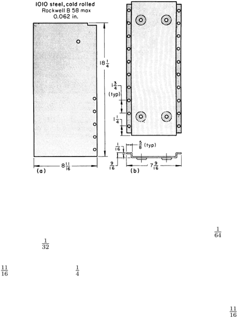
Example 5: Change from Three Separate Dies to a Progressive Die.
The part shown in Fig. 12(b) was produced from 1.6 mm (0.062 in.) thick cold-rolled 1010 steel that had a hardness of 58
HRB maximum. A progressive die, which made a finished part at each press stroke, replaced three dies in which 12 press
strokes were required for producing one piece. The separate dies were a standard piercing and notching die, an embossing
die, and a conventional V-die. Setup time for each die was 30 min.
Fig. 12 Strut that was produced in fewer press strokes with a progressive die than with standard press-
brake
tooling. (a) Blank after first stroke with standard tooling. (b) Finished part. Dimensions given in inches.
The cost of the progressive die was justified for the annual production of 60,000 parts (break-even point was 34,000
parts). Both methods made parts that were within the maximum dimensional tolerance of ±0.4 mm (± in.), and to the
maximum bend radius of 0.8 mm ( in.).
The original dies had been used in an 890 kN (100 tonf) press brake that operated at 600 strokes per hour on sheared
blanks 220 mm (8 in.) wide by 464 mm (18 in.) long. The press-brake operation consisted of piercing five holes in
the flange and one in the center and notching one corner (Fig. 12a). The other holes and the three other corner notches
were produced with three more strokes, with the workpiece being turned after each stroke. Four more strokes were needed
for embossing four holes (Fig. 12b). Bending required four strokes, bringing the total to 12 strokes.
The progressive die, made of O1 tool steel, pierced, embossed, notched, and cut off the strut from 220 mm (8 in.) wide
coil stock at a rate of 225 per hour. The die was set up in a 2700 kN (300 tonf) mechanical press. Mineral oil was used as
the lubricant for both methods.

Press Bending of Low-Carbon Steel
Transfer Dies
Transfer dies are similar in operation to progressive dies. The important difference is in the method of transferring
workpieces from station to station. The workpieces remain fastened to the stock strip in a progressive die, but they are
separate in a transfer die and are transferred from station to station within the die between press strokes by mechanical
fingers, levers, or cams. Transfer dies are particularly suited to the fabrication of parts that would be difficult to connect to
the stock skeleton with carrier tabs. Bends that cannot be made in a single step are often made in several stages in transfer
dies, and bending is often combined with cutting or other forming operations in transfer dies.
The advantages of transfer dies for bending include high production rate, greater versatility than progressive dies, and
more efficient use of stock. The last advantage is ordinarily achieved by blanking in a separate press, which permits close
nesting of parts. The disadvantages include high equipment cost (for dies, press attachments, and feeding devices), high
setup and tool maintenance cost, difficulty in handling thin work metal, and poor applicability to large or oddly shaped
parts that need variations in blankholder pressure and contour.
Transfer dies are well suited to the bending of small rings, cups, and cylinders. Transfer dies are used to make rings with
one joint.
Press Bending of Low-Carbon Steel
Lubrication
Lubrication is less important for most bending operations than for other types of forming. In many bending operations, no
lubricant is used; in others, the mill oil remaining on the stock or a light mineral oil applied before forming is sufficient to
prevent galling.
Exceptions to this practice are hole flanging, compression and stretch flanging, an severe bending in which wiping,
ironing, or drawing of the work metal may call for more effective lubrication. More information on lubrication, including
recommendations, is available in the article "Selection and Use of Lubricants in Forming of Sheet Metal" in this Volume.
Three examples in this article describe applications in which lubricants were used because of the nature of the bending
operations performed. In Example 1, in which accuracy was important and sharp-radius bends were made parallel with
the direction of rolling, the workpiece was lubricated with mineral oil before bending. In Example 2, mineral oil was
applied to the workpiece before flattening a bend to 180°. In Example 3, a soluble oil-water mixture was used with a
compound die that had a wiping component.
Press Bending of Low-Carbon Steel
Bending Cylindrical Parts
Generally, as the bend radius becomes larger, the allowance for springback must be more generous because less of the
bent metal has been stressed beyond its yield strength. Very large radii cannot be easily formed by ordinary bending, but
must be stretch formed (see the article "Stretch Forming" in this Volume). For large-radius bends, in which the workpiece
is formed to half a circle or more, the bend is often made in several stages, as in the following example.
Example 6: Bending a Cylindrical Part in a Progressive Die.
The part shown in Fig. 13 was made in a six-station progressive die from 1.2 mm (0.048 in.) thick cold-rolled 1010 or
1020 steel having a hardness of 65 to 75 HRB. The part was a valve used to adjust the size of the air intake in a gas
burner.