Baker R.C. Flow Measurement Handbook: Industrial Designs, Operating Principles, Performance, and Applications
Подождите немного. Документ загружается.

9.3 CALIBRATION, ENVIRONMENTAL COMPENSATION, AND OTHER FACTORS 197
e. The low flow rate and rotation may markedly alter the liquid flows on sliding
and stationary members. The bearing and clearance drag may be changed.
Back Slip Due to System Effects
f. The quantity of liquid in the pipework may not be precisely the same before
and after the slip test. For instance, 20 liters of liquid in a slip test fill 2.6 m of a
100-mm diameter pipe.
g. In tests using manual and automatic valves, one may be closed at the start of
the test and both closed at the end, slightly altering the pipe volume.
h. Upstream valve control may cause pressure changes leading to volume changes,
i. Gas may come out of solution during the test.
Back Slip Due to Calibration Vessel
j.
The measurement uncertainty oi the vessel is not better than about ±0.2% for
so short a run.
It appears that various effects occasionally may come together to cause the observa-
tion of back slip.
The observations of back slip appear likely to result from uncertainties in opera-
tion of the meter at low rotation. Variation during rotation can become important if
flows of about 15 liters are involved because this may result, for a 100-mm meter, in
less than two rotations. Thus the nonuniform calibrator transmission or variation in
vane clearance may occasionally result in an increased recorded rotation for a given
volume passed.
9.3.5 THE EFFECTS OF TEMPERATURE AND PRESSURE CHANGES
The effects of temperature and pressure variation are given in Equations (9.A.9) to
(9.A.18), using values in Figure 9.13. These values are, therefore, for a moving vane
type meter but will give some indication of the effect on others. Making use of values
of a
m
of 0.23 x 10~
4
for aluminum, 0.11 x 10~
4
for mild steel and cast iron, and of
Git
of 9 x 10~
4
for oil, Table 9.1 gives values for temperature changes of 10°C and
pressure changes of 1 bar taking E for mild steel as 207 GN/m
2
. One manufacturer
gives the effect of changes in pressure and temperature on the meter excluding the
effect of liquid changes, and this is reproduced in Figure 9.15.
9.3.6 THE EFFECTS OF GAS IN SOLUTION
Another effect not considered so far will be the presence of dissolved gas in solution.
The dissolved gas may cause no change in liquid volume, although it may have a
large volume in gaseous form. The mass of gas involved will often be small enough
to neglect.
However, under sudden pressure reduction, the gas may come out of solution.
This might occur during a slippage test, if the test is controlled on a valve upstream
of the meter, and might cause the rotor to turn due to the presence of the gas alone.
The problem can also arise when metering liquified petroleum gas (LPG) if the
back pressure on the meter is insufficient.
198
POSITIVE DISPLACEMENT FLOWMETERS
Table 9.1. The effects of temperature and
pressure changes
Description
Metal/
Liquid
For temperature change
Flowmeter
expansion
Differential
expansion
Liquid-density
change
Al
M.S.
Al
M.S.
Al/M.S.
Oil
For pressure change of 1
Flowmeter
expansion
Leakage gap
radial
Leakage gap
axial
M.S.
M.S.
M.S.
Aq
v
/q
v
(°/o)
of IOC
0.07
0.03
—
—
—
0.9
bar
0.003
—
At/t(%) '
— '*
v
37
i:
18 ?
19 I
v
— :
1.2 f
0.4 ?
9.4 ACCURACY AND CALIBRATION
percentage
change in
indication
0.02
0.01 -
Accuracy achievable from these meters will be highly dependent on the particular
design. Values have been suggested earlier. At the top end, the sliding vane meters
can achieve an accuracy that may be limited by the means of calibration. It is highly
likely that precision devices such as the oval gear meter will approach the level of
performance of the sliding vane meters.
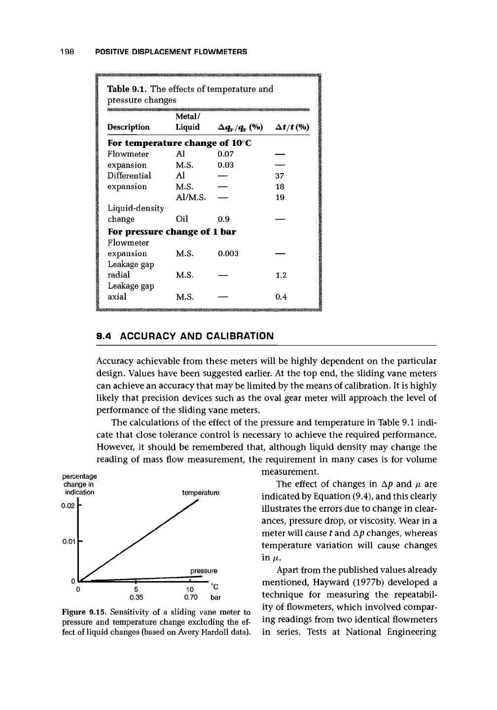
The calculations of the effect of the pressure and temperature in Table 9.1 indi-
cate that close tolerance control is necessary to achieve the required performance.
However, it should be remembered that, although liquid density may change the
reading of mass flow measurement, the requirement in many cases is for volume
measurement.
The effect of changes in Ap and \i are
indicated by Equation (9.4), and this clearly
illustrates the errors due to change in clear-
ances,
pressure drop, or viscosity. Wear in a
meter will cause t and Ap changes, whereas
temperature variation will cause changes
in \i.
Apart from the published values already
mentioned, Hayward (1977b) developed a
technique for measuring the repeatabil-
ity of flowmeters, which involved compar-
ing readings from two identical flowmeters
in series. Tests at National Engineering
temperature
pressure
°C
bar
Figure 9.15. Sensitivity of a sliding vane meter to
pressure and temperature change excluding the ef-
fect of liquid changes (based on Avery Hardoll data).
9.5 PRINCIPAL DESIGNS OF GAS METERS 199
Laboratory, Scotland, suggested that repeatabilities better than 10 ppm (0.001%)
could be obtained with vane-type flowmeters provided that the drift in readings,
which seemed to arise in the shaft encoder, could be eliminated.
Hayward (1979) commented that the rangeability was about
20:1,
linearity was
±0.05%,
and accuracy when newly calibrated was ±0.2% of volume over the range.
He suggested that these meters perform best in the maximum flow rate range of
0.002-0.05 m
3
/s.
Barnes (1982) underlined the superior accuracy, repeatability (within 0.05%),
and reliability of positive displacement flowmeters but drew attention to inaccuracies
that arose if the liquid contained free or entrained
gases.
Data from fuel oil, gasoline,
and propane were presented to show that the accuracy was highest when the meters
were used to measure flow at about 25% of the rated flow capacity. At both higher
and lower flows, increased slippage occurs and causes the meter to underregister.
The meters were also relatively insensitive to changes in viscosity. Barnes suggested
that if a meter initially calibrated for a liquid of
1
cP was used with a liquid of 100 cP,
the resulting shift in accuracy was of order 1.2%.
Reitz (1979) quoted the following figures: repeatability within 0.02%, accuracy
±0.25%
over a
20:1
flow range, and pressure loss 3 psi (0.2 bar) for liquids of viscosity
1 cP. He suggested that fluids with viscosities in the range 0.1 cP (gas) to 10
6
cP
(liquid) could be metered in this way. He noted that errors arise from excessive wear,
which increases slippage and causes underregistration, and entrained gas bubbles,
which occupy part of the measuring chamber and cause the meter to give too high
a reading.
Kent Meters (Scanes 1974) quoted an accuracy of
±0.5%
for a domestic oil meter
designed for rates as low as 0.1-101/h. The temperature range was quoted as -10°C
to 35°C, although temperatures as high as 90°C had apparently been recorded at
meter boxes sited in direct sunlight.
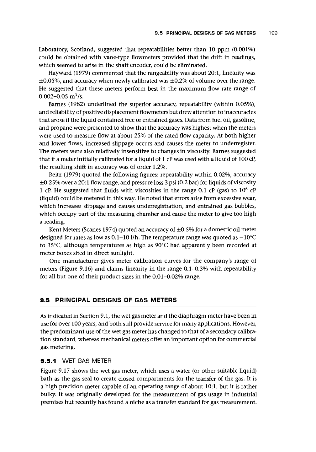
One manufacturer gives meter calibration curves for the company's range of
meters (Figure 9.16) and claims linearity in the range 0.1-0.3% with repeatability
for all but one of their product sizes in the 0.01-0.02% range.
9.5 PRINCIPAL DESIGNS OF GAS METERS
As
indicated in Section
9.1,
the wet gas meter and the diaphragm meter have been in
use for over 100
years,
and both still provide service for many applications. However,
the predominant use of the wet gas meter has changed to that of a secondary calibra-
tion standard, whereas mechanical meters offer an important option for commercial
gas metering.
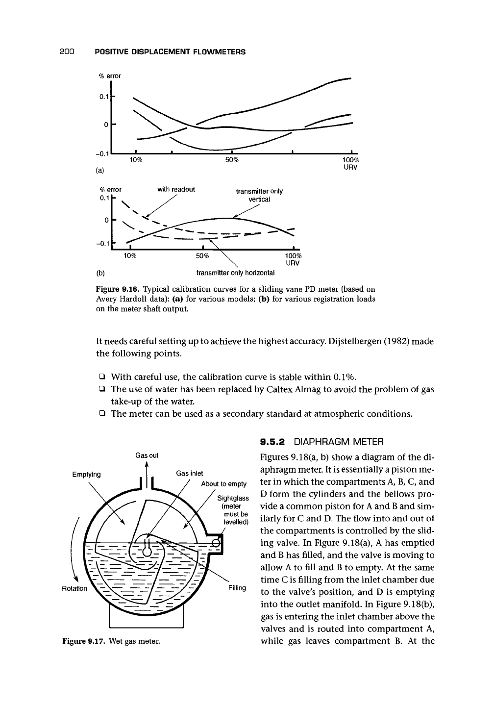
9.5.1 WET GAS METER
Figure 9.17 shows the wet gas meter, which uses a water (or other suitable liquid)
bath as the gas seal to create closed compartments for the transfer of the gas. It is
a high precision meter capable of an operating range of about 10:1, but it is rather
bulky. It was originally developed for the measurement of gas usage in industrial
premises but recently has found a niche as a transfer standard for gas measurement.
200
POSITIVE DISPLACEMENT FLOWMETERS
100%
URV
transmitter only horizontal
Figure 9.16. Typical calibration curves for a sliding vane PD meter (based on
Avery Hardoll data): (a) for various models; (b) for various registration loads
on the meter shaft output.
It needs careful setting up to achieve the highest accuracy. Dijstelbergen (1982) made
the following points.
• With careful use, the calibration curve is stable within
0.1%.
• The use of water has been replaced by Caltex Almag to avoid the problem of gas
take-up of the water.
• The meter can be used as a secondary standard at atmospheric conditions.
Gas out
Emptying
Gas inlet
About to empty
Sightglass
(meter
must be
levelled)
Rotation
\-\— /— —/~
A
Figure 9.17. Wet gas meter.
Filling
9.5.2 DIAPHRAGM METER
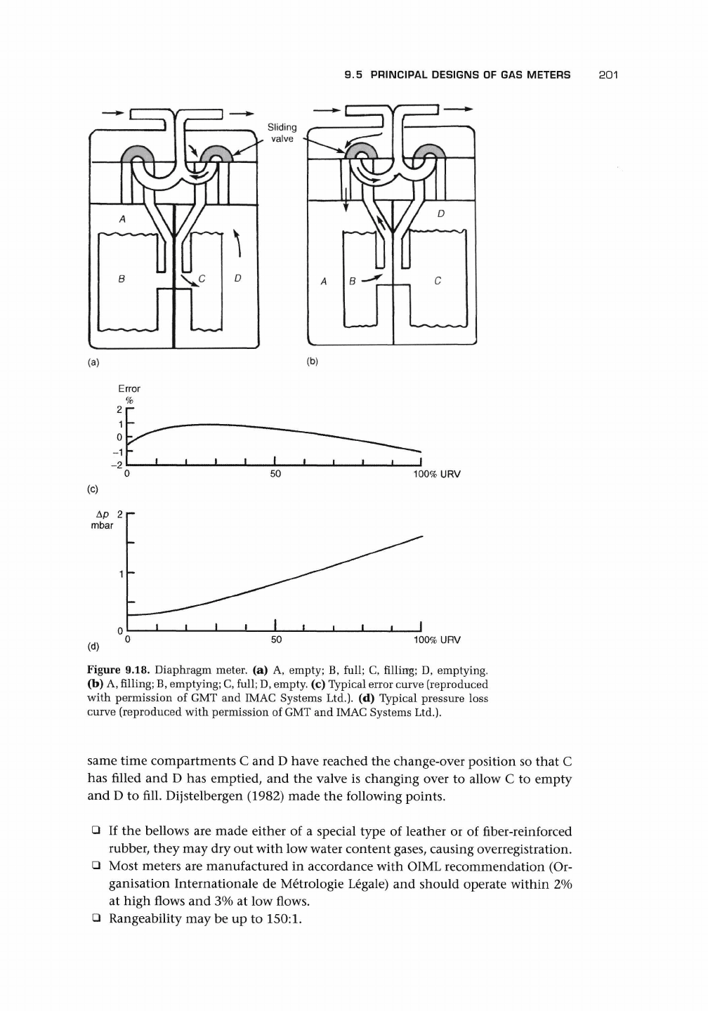
Figures 9.18(a, b) show a diagram of the di-
aphragm meter. It is essentially a piston me-
ter in which the compartments
A,
B, C, and
D form the cylinders and the bellows pro-
vide a common piston for
A
and
B
and sim-
ilarly for C and D. The flow into and out of
the compartments is controlled by the slid-
ing valve. In Figure 9.18(a), A has emptied
and
B
has filled, and the valve is moving to
allow A to fill and
B
to empty. At the same
time C is filling from the inlet chamber due
to the valve's position, and D is emptying
into the outlet manifold. In Figure 9.18(b),
gas is entering the inlet chamber above the
valves and is routed into compartment A,
while gas leaves compartment B. At the
9.5 PRINCIPAL DESIGNS OF GAS METERS
201
Sliding
* valve
(b)
Error
50
100% URV
(c)
Ap 2p
mbar
(d)
50
100% URV
Figure 9.18. Diaphragm meter, (a) A, empty; B, full; C, filling; D, emptying.
(b) A, filling;
B,
emptying; C, full;
D,
empty, (c) Typical error curve (reproduced
with permission of GMT and IMAC Systems Ltd.). (d) Typical pressure loss
curve (reproduced with permission of GMT and IMAC Systems Ltd.).
same time compartments C and D have reached the change-over position so that C
has filled and D has emptied, and the valve is changing over to allow C to empty
and D to fill. Dijstelbergen (1982) made the following points.
• If the bellows are made either of a special type of leather or of fiber-reinforced
rubber, they may dry out with low water content gases, causing overregistration.
• Most meters are manufactured in accordance with OIML recommendation (Or-
ganisation Internationale de Metrologie Legale) and should operate within 2%
at high flows and 3% at low flows.
• Rangeability may be up to
150:1.
202
POSITIVE DISPLACEMENT FLOWMETERS
The typical measurement uncertainty is ±1% [Figure 19.18(c)]. The maximum
allowable inlet pressure on some designs is about 0.1 bar above atmospheric, but
it may be up to 1 bar on other special versions. The coupling from the mechanical
meter to the output may consist of a magnetic coupling to the display. Operating
temperature range is typically -20 to +60°C. The meters operate to DIN 3374 and
BS
4161.
The pressure loss through the meter is about 1.5 mbar [Figure 19.18(d)].
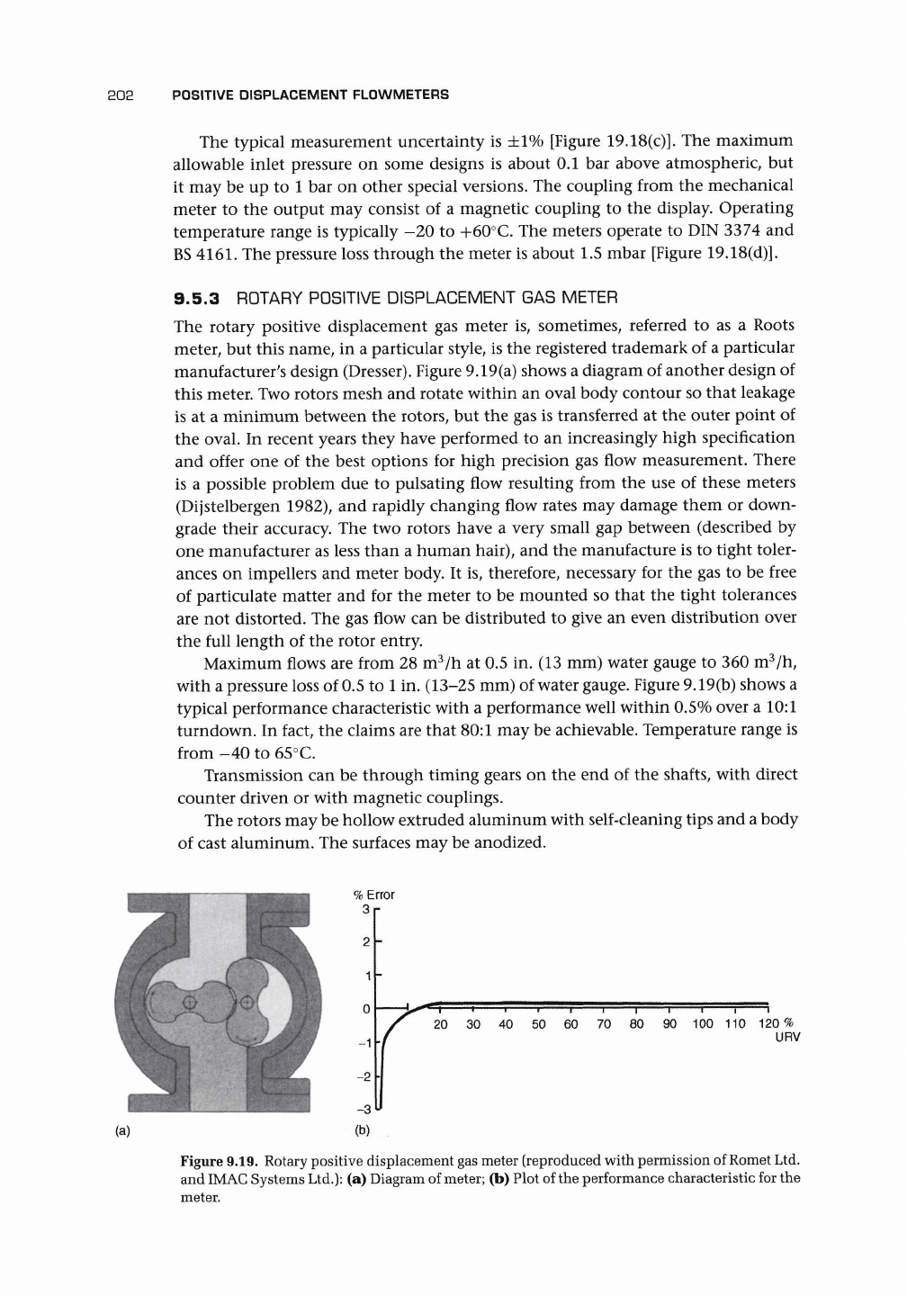
9.5.3 ROTARY POSITIVE DISPLACEMENT GAS METER
The rotary positive displacement gas meter is, sometimes, referred to as a Roots
meter, but this name, in a particular style, is the registered trademark of a particular
manufacturer's design (Dresser). Figure 9.19(a) shows a diagram of another design of
this meter. Two rotors mesh and rotate within an oval body contour so that leakage
is at a minimum between the rotors, but the gas is transferred at the outer point of
the oval. In recent years they have performed to an increasingly high specification
and offer one of the best options for high precision gas flow measurement. There
is a possible problem due to pulsating flow resulting from the use of these meters
(Dijstelbergen 1982), and rapidly changing flow rates may damage them or down-
grade their accuracy. The two rotors have a very small gap between (described by
one manufacturer as less than a human hair), and the manufacture is to tight toler-
ances on impellers and meter body. It is, therefore, necessary for the gas to be free
of particulate matter and for the meter to be mounted so that the tight tolerances
are not distorted. The gas flow can be distributed to give an even distribution over
the full length of the rotor entry.
Maximum flows are from 28 m
3
/h at 0.5 in. (13 mm) water gauge to 360 m
3
/h,
with a pressure loss of 0.5 to
1
in. (13-25 mm) of water gauge. Figure 9.19(b) shows a
typical performance characteristic with a performance well within 0.5% over a 10:1
turndown. In fact, the claims are that 80:1 may be achievable. Temperature range is
from -40 to 65°C.
Transmission can be through timing gears on the end of the shafts, with direct
counter driven or with magnetic couplings.
The rotors may be hollow extruded aluminum with self-cleaning tips and a body
of cast aluminum. The surfaces may be anodized.
(a)
% Error
3
2
1
0
-2
-3
(b)
20 30 40 50 60 70 80 90 100 110 120%
URV
Figure 9.19. Rotary positive displacement gas meter (reproduced with permission of Romet Ltd.
and IMAC Systems
Ltd.):
(a) Diagram of meter; (b) Plot of the performance characteristic for the
meter.
9.6 POSITIVE DISPLACEMENT METERS FOR MULTIPHASE FLOWS 203
The CVM meter
is
of similar design to Figure 9.3(b) with a main rotor that consists
of four vanes or moving walls that form metering compartments. The second rotor
is a sealing rotor that returns the vanes to the inlet side of the meter. The second
rotor may be two- or three-lobed, and its rotation will be precisely linked to that
of the main rotor. According to Dijstelbergen (1982), it is suitable for high pressure
metering, does not cause pulsations in the flow, handles flows up to 1,200 m
3
/h, and
a repeatability of 0.05% may be achievable.
9.6 POSITIVE DISPLACEMENT METERS
FOR MULTIPHASE FLOWS
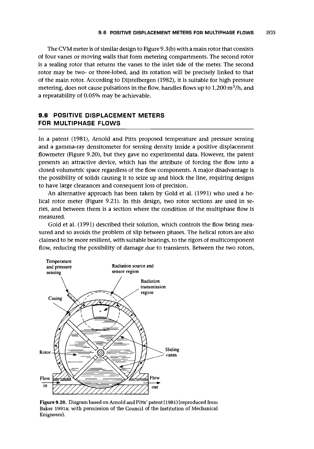
In a patent (1981), Arnold and Pitts proposed temperature and pressure sensing
and a gamma-ray densitometer for sensing density inside a positive displacement
flowmeter (Figure 9.20), but they gave no experimental data. However, the patent
presents an attractive device, which has the attribute of forcing the flow into a
closed volumetric space regardless of the flow components.
A
major disadvantage is
the possibility of solids causing it to seize up and block the line, requiring designs
to have large clearances and consequent loss of precision.
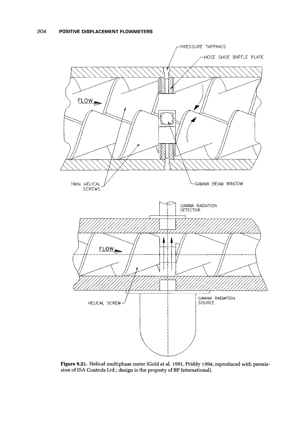
An alternative approach has been taken by Gold et al. (1991) who used a he-
lical rotor meter (Figure 9.21). In this design, two rotor sections are used in se-
ries,
and between them is a section where the condition of the multiphase flow is
measured.
Gold et al. (1991) described their solution, which controls the flow being mea-
sured and so avoids the problem of slip between phases. The helical rotors are also
claimed to be more resilient, with suitable bearings, to the rigors of multicomponent
flow, reducing the possibility of damage due to transients. Between the two rotors,
Temperature
and pressure Radiation source and
sensing sensor region
Radiation
transmission
region
Sliding
vanes
Figure 9.20. Diagram based on Arnold and Pitts' patent (1981) (reproduced from
Baker 1991a; with permission of the Council of the Institution of Mechanical
Enigneers).
204 POSITIVE DISPLACEMENT FLOWMETERS
PRESSURE TAPPINGS
HOSE SHOE BAFFLE PLATE
TWIN HELICAL
SCREWS
GAMMA BEAM WINDOW
GAMMA RADIATION
DETECTOR
Figure 9.21. Helical multiphase meter (Gold et al.
1991,
Priddy 1994; reproduced with permis-
sion of ISA Controls Ltd.; design is the property of
BP
International).
9.8 APPLICATIONS, ADVANTAGES, AND DISADVANTAGES 205
t I
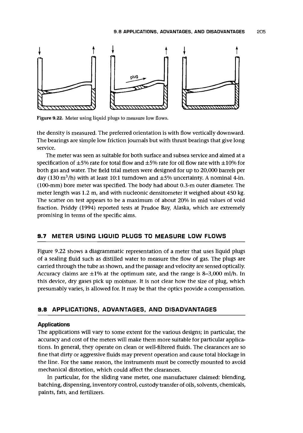
Figure 9.22. Meter using liquid plugs to measure low flows.
the density is measured. The preferred orientation is with flow vertically downward.
The bearings are simple low friction journals but with thrust bearings that give long
service.
The meter was seen as suitable for both surface and subsea service and aimed at a
specification of ±5% rate for total flow and ±5% rate for oil flow rate with ±10% for
both gas and water. The field trial meters were designed for up to 20,000 barrels per
day (130 m
3
/h) with at least 10:1 turndown and ±5% uncertainty. A nominal 4-in.
(100-mm) bore meter was specified. The body had about 0.3-m outer diameter. The
meter length was 1.2 m, and with nucleonic densitometer it weighed about 450 kg.
The scatter on test appears to be a maximum of about 20% in mid values of void
fraction. Priddy (1994) reported tests at Prudoe Bay, Alaska, which are extremely
promising in terms of the specific aims.
9.7 METER USING LIQUID PLUGS TO MEASURE LOW FLOWS
Figure 9.22 shows a diagrammatic representation of a meter that uses liquid plugs
of a sealing fluid such as distilled water to measure the flow of gas. The plugs are
carried through the tube as shown, and the passage and velocity are sensed optically.
Accuracy claims are ±1% at the optimum rate, and the range is 8-3,000 ml/h. In
this device, dry gases pick up moisture. It is not clear how the size of plug, which
presumably varies, is allowed for. It may be that the optics provide a compensation.
9.8 APPLICATIONS, ADVANTAGES, AND DISADVANTAGES
Applications
The applications will vary to some extent for the various designs; in particular, the
accuracy and cost of the meters will make them more suitable for particular applica-
tions.
In general, they operate on clean or well-filtered fluids. The clearances are so
fine that dirty or aggressive fluids may prevent operation and cause total blockage in
the line. For the same reason, the instruments must be correctly mounted to avoid
mechanical distortion, which could affect the clearances.
In particular, for the sliding vane meter, one manufacturer claimed: blending,
batching, dispensing, inventory control, custody transfer of
oils,
solvents, chemicals,
paints, fats, and fertilizers.
206 POSITIVE DISPLACEMENT FLOWMETERS
For high viscosity fluids, the flow passage may create too great a pressure drop.
For some
oils,
the temperature of the liquid may need to be sensed and compensation
used.
Presumably, the design developed for multiphase flows will eliminate the need
for well-filtered fluids.
Advantages
The advantages are seen in high precision instruments, and their accuracy after cali-
bration is possibly only limited by the calibration facility
used.
Most are little affected
by viscosity. The most accurate ones among them, therefore, provide a device that
is highly suitable for custody transfer and fiscal transfer applications.
Disadvantages
The meters may create pulsations and may
be
subject to damage from rapidly varying
flows.
Damage to the meters causing them to stop rotating will also cause total line
blockage. They may have a high initial price and may require careful maintenance
with high associated costs. The meters may create a substantial pressure loss.
9.9 CHAPTER CONCLUSIONS
What is likely to be the future of such meter designs? No doubt other clever designs
will be introduced such as that selected as a utility gas meter (Kim et al. 1993b,
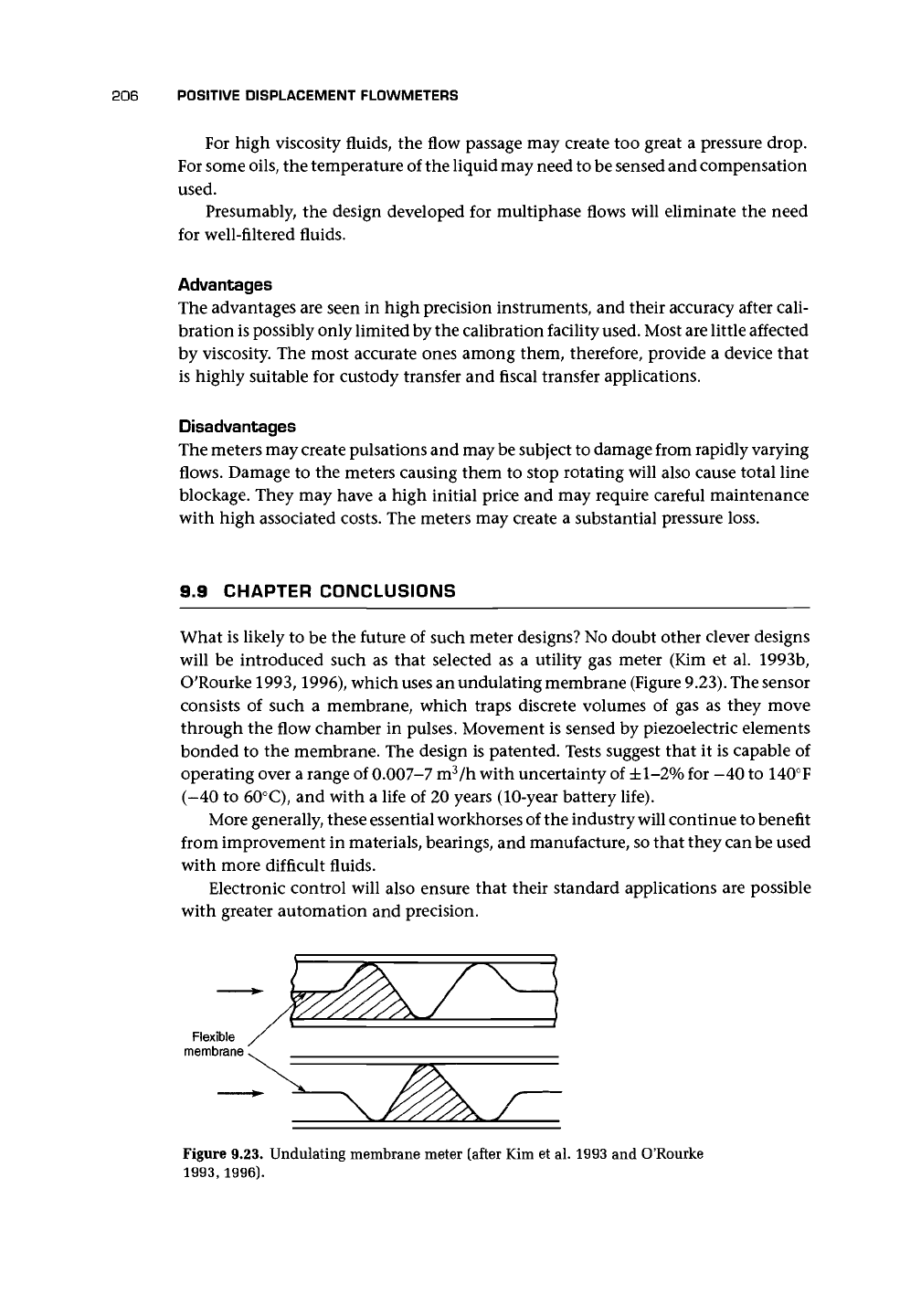
O'Rourke 1993,1996), which uses an undulating membrane (Figure 9.23). The sensor
consists of such a membrane, which traps discrete volumes of gas as they move
through the flow chamber in pulses. Movement is sensed by piezoelectric elements
bonded to the membrane. The design is patented. Tests suggest that it is capable of
operating over a range of 0.007-7 m
3
/h with uncertainty of ±1-2% for -40 to 140°F
(-40 to 60°C), and with a life of 20 years (10-year battery life).
More generally, these essential workhorses of the industry will continue to benefit
from improvement in materials, bearings, and manufacture, so that they can be used
with more difficult fluids.
Electronic control will also ensure that their standard applications are possible
with greater automation and precision.
Figure 9.23. Undulating membrane meter (after Kim et al. 1993 and O'Rourke
1993,
1996).