Baker R.C. Flow Measurement Handbook: Industrial Designs, Operating Principles, Performance, and Applications
Подождите немного. Документ загружается.

10.1
INTRODUCTION
217
Profile
A
Profile
B
<t
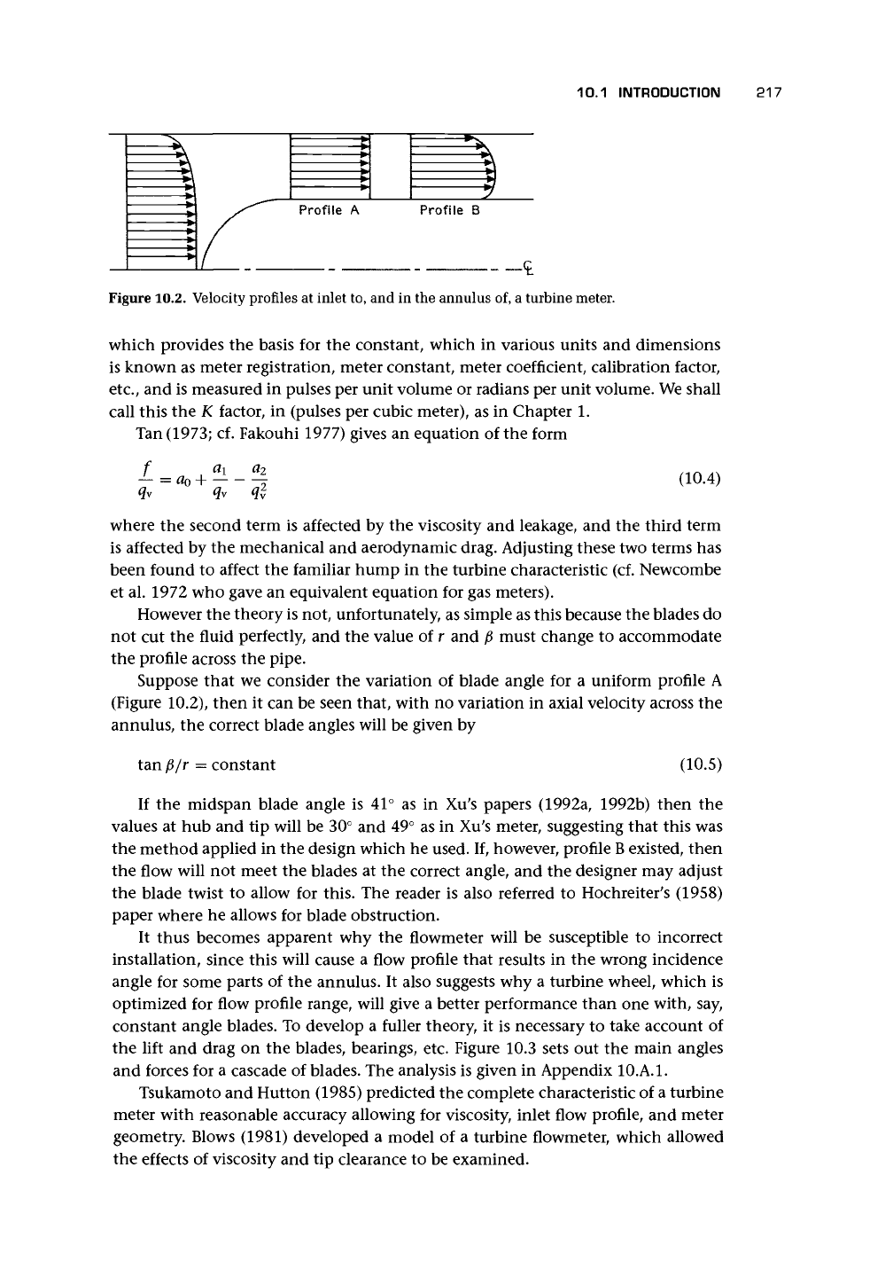
Figure
10.2.
Velocity profiles
at
inlet
to, and in the
annulus
of, a
turbine
meter.
which provides the basis for the constant, which in various units and dimensions
is known as meter registration, meter constant, meter coefficient, calibration factor,
etc.,
and is measured in pulses per unit volume or radians per unit volume. We shall
call this the K factor, in (pulses per cubic meter), as in Chapter 1.
Tan
(1973;
cf. Fakouhi 1977) gives an equation of the form
-*- = a
0
+
q
v
q
y
q*
(10.4)
where the second term is affected by the viscosity and leakage, and the third term
is affected by the mechanical and aerodynamic drag. Adjusting these two terms has
been found to affect the familiar hump in the turbine characteristic (cf. Newcombe
et al. 1972 who gave an equivalent equation for gas meters).
However the theory is not, unfortunately, as simple as this because the blades do
not cut the fluid perfectly, and the value of r and
/3
must change to accommodate
the profile across the pipe.
Suppose that we consider the variation of blade angle for a uniform profile A
(Figure 10.2), then it can be seen that, with no variation in axial velocity across the
annulus, the correct blade angles will be given by
tan/3/r = constant
(10.5)
If the midspan blade angle is 41° as in Xu's papers (1992a, 1992b) then the
values at hub and tip will be 30° and 49° as in Xu's meter, suggesting that this was
the method applied in the design which he used. If, however, profile
B
existed, then
the flow will not meet the blades at the correct angle, and the designer may adjust
the blade twist to allow for this. The reader is also referred to Hochreiter's (1958)
paper where he allows for blade obstruction.
It thus becomes apparent why the flowmeter will be susceptible to incorrect
installation, since this will cause a flow profile that results in the wrong incidence
angle for some parts of the annulus. It also suggests why a turbine wheel, which is
optimized for flow profile range, will give a better performance than one with, say,
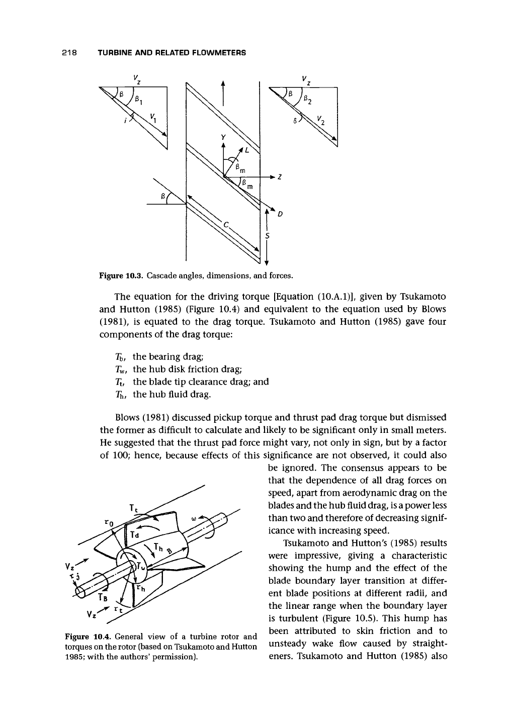
constant angle blades. To develop a fuller theory, it is necessary to take account of
the lift and drag on the blades, bearings, etc. Figure 10.3 sets out the main angles
and forces for a cascade of blades. The analysis is given in Appendix
10.A.1.
Tsukamoto and Hutton (1985) predicted the complete characteristic of a turbine
meter with reasonable accuracy allowing for viscosity, inlet flow profile, and meter
geometry. Blows (1981) developed a model of a turbine flowmeter, which allowed
the effects of viscosity and tip clearance to be examined.
218
TURBINE
AND
RELATED FLOW METERS
Figure
10.3.
Cascade
angles,
dimensions,
and
forces.
The equation for the driving torque [Equation (10.A.1)], given by Tsukamoto
and Hutton (1985) (Figure 10.4) and equivalent to the equation used by Blows
(1981),
is equated to the drag torque. Tsukamoto and Hutton (1985) gave four
components of the drag torque:
T
b
, the bearing drag;
T
w
,
the hub
disk friction drag;
T
t
,
the
blade
tip
clearance drag;
and
T
h
,
the hub
fluid drag.
Blows (1981) discussed pickup torque
and
thrust
pad
drag torque
but
dismissed
the former
as
difficult
to
calculate
and
likely
to be
significant only
in
small meters.
He suggested that
the
thrust
pad
force might vary,
not
only
in
sign,
but by a
factor
of
100;
hence, because effects
of
this significance
are not
observed,
it
could also
be ignored.
The
consensus appears
to be
that
the
dependence
of all
drag forces
on
speed, apart from aerodynamic drag
on the
blades
and the hub
fluid drag,
is a
power less
than
two and
therefore
of
decreasing
signif-
icance with increasing speed.
Tsukamoto
and
Hutton's (1985) results
were impressive, giving
a
characteristic
showing
the
hump
and the
effect
of the
blade boundary layer transition
at
differ-
ent blade positions
at
different radii,
and
the linear range when
the
boundary layer
is turbulent (Figure 10.5). This hump
has
,
.
r
,
been attributed
to
skin friction
and to
Figure
10.4.
General view
of a
turbine rotor
and
torques on the rotor (based on Tsukamoto and Hutton unsteady wake flow caused by straight-
1985;
with the authors' permission). eners. Tsukamoto and Hutton (1985) also
10.1 INTRODUCTION
219
Turbulent
Transition /
—
Laminar . 1
3.4
3.2
Power Law Upstream Profile
1*10~
6
m
2
/s
Parabolic Upstream Profile
Measured by Fakouhi (1977)
o v »
• 21
A 47
a 170
, , , , • • .,! . ..... ..I I
10°
10*
10°
Re
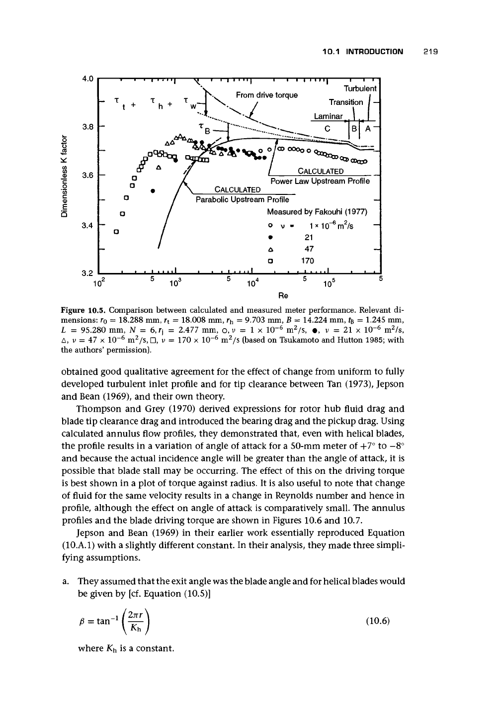
Figure 10.5. Comparison between calculated and measured meter performance. Relevant di-
mensions: r
0
= 18.288 mm, r
t
= 18.008 mm, r
h
= 9.703 mm, B = 14.224 mm, t
B
= 1-245 mm,
L = 95.280 mm, N = 6,fj = 2.477 mm, o, v = 1 x 10"
6
m
2
/s, •. v = 21 x 10~
6
m
2
/s,
A, v = 47 x 10~
6
m
2
/s, D, v = 170 x 10~
6
m
2
/s (based on Tsukamoto and Hutton 1985; with
the authors' permission).
obtained good qualitative agreement for the effect of change from uniform to fully
developed turbulent inlet profile and for tip clearance between Tan (1973), Jepson
and Bean (1969), and their own theory.
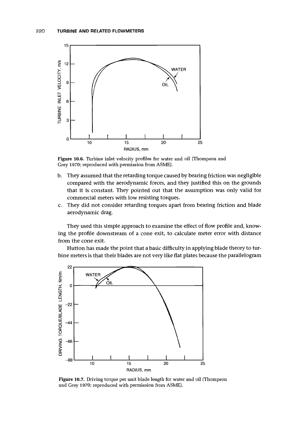
Thompson and Grey (1970) derived expressions for rotor hub fluid drag and
blade tip clearance drag and introduced the bearing drag and the pickup drag. Using
calculated annulus flow profiles, they demonstrated that, even with helical blades,
the profile results in a variation of angle of attack for a 50-mm meter of +7° to -8°
and because the actual incidence angle will be greater than the angle of attack, it is
possible that blade stall may be occurring. The effect of this on the driving torque
is best shown in a plot of torque against radius. It is also useful to note that change
of fluid for the same velocity results in a change in Reynolds number and hence in
profile, although the effect on angle of attack is comparatively small. The annulus
profiles and the blade driving torque are shown in Figures 10.6 and 10.7.
Jepson and Bean (1969) in their earlier work essentially reproduced Equation
(10.A.1) with a slightly different constant. In their analysis, they made three simpli-
fying assumptions.
a. They assumed that the exit angle was the blade angle and for helical blades would
be given by [cf. Equation (10.5)]
= tan"
1
2nr\
(10.6)
where K
h
is a constant.
220 TURBINE AND RELATED FLOWMETERS
10
IITY, m/s
I
9
1—
JJ
? 6
LJU
-7
TURBir
CO
n
-
-
—
-
!
// ^^v WATER
II *%
II
OIL
V
/
I 1 ! 1 1
10
15
RADIUS, mm
20
25
Figure 10.6. Turbine inlet velocity profiles for water and oil (Thompson and
Grey 1970; reproduced with permission from ASME).
b.
They assumed that the retarding torque caused by bearing friction was negligible
compared with the aerodynamic forces, and they justified this on the grounds
that it is constant. They pointed out that the assumption was only valid for
commercial meters with low resisting torques.
c. They did not consider retarding torques apart from bearing friction and blade
aerodynamic drag.
They used this simple approach to examine the effect of flow profile and, know-
ing the profile downstream of a cone exit, to calculate meter error with distance
from the cone exit.
Hutton has made the point that a basic difficulty in applying blade theory to tur-
bine meters is that their blades are not very like flat plates because the parallelogram
DC
Q
LU
-22 —
5
=> -44 —
O
DC
O
S -66 -
-88
Figure 10.7. Driving torque per unit blade length for water and oil (Thompson
and Grey 1970; reproduced with permission from ASME).
10.2 PRECISION LIQUID METERS
221
Calibration constant shift
Turbine blade profile
Degree of
separation
I
Linearization by controlled flow separation
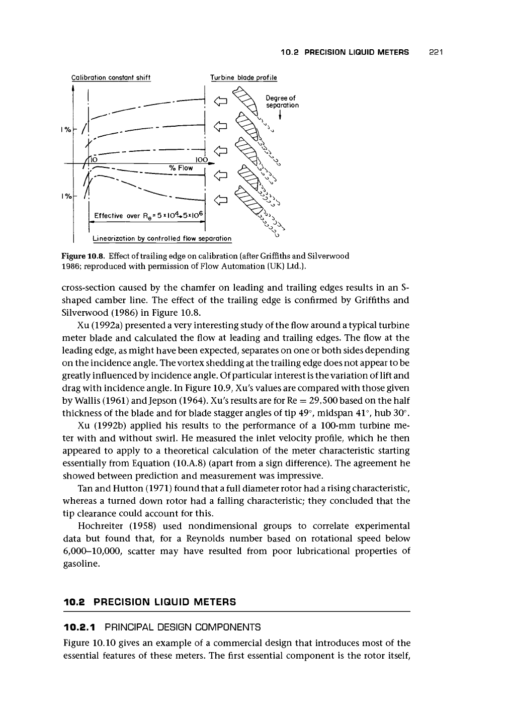
Figure 10.8. Effect of trailing edge on calibration (after Griffiths and Silverwood
1986;
reproduced with permission of Flow Automation (UK) Ltd.).
cross-section caused by the chamfer on leading and trailing edges results in an S-
shaped camber line. The effect of the trailing edge is confirmed by Griffiths and
Silverwood (1986) in Figure 10.8.
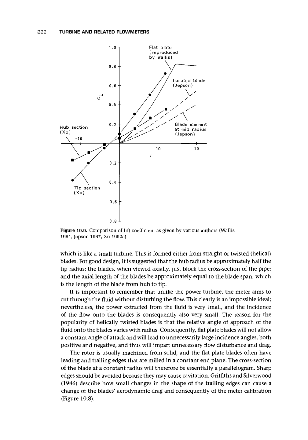
Xu (1992a) presented
a
very interesting study of the flow around a typical turbine
meter blade and calculated the flow at leading and trailing edges. The flow at the
leading edge, as might have been expected, separates on one or both sides depending
on the incidence angle. The vortex shedding at the trailing edge does not appear to be
greatly influenced by incidence angle. Of particular interest
is
the variation of lift and
drag with incidence angle. In Figure 10.9, Xu
;
s values are compared with those given
by Wallis (1961) andjepson (1964). Xu's results are for
Re
= 29,500 based on the half
thickness of the blade and for blade stagger angles of tip 49°, midspan 41°, hub 30°.
Xu (1992b) applied his results to the performance of a 100-mm turbine me-
ter with and without swirl. He measured the inlet velocity profile, which he then
appeared to apply to a theoretical calculation of the meter characteristic starting
essentially from Equation (10.A.8) (apart from a sign difference). The agreement he
showed between prediction and measurement was impressive.
Tan and Hutton (1971) found that a full diameter rotor had a rising characteristic,
whereas a turned down rotor had a falling characteristic; they concluded that the
tip clearance could account for this.
Hochreiter (1958) used nondimensional groups to correlate experimental
data but found that, for a Reynolds number based on rotational speed below
6,000-10,000, scatter may have resulted from poor lubricational properties of
gasoline.
10.2 PRECISION LIQUID METERS
10.2.1 PRINCIPAL DESIGN COMPONENTS
Figure 10.10 gives an example of a commercial design that introduces most of the
essential features of these meters. The first essential component is the rotor
itself,
222 TURBINE AND RELATED FLOWMETERS
1
.0
-i
0.8 -
0.6 --
0.4 --
0.2 "-
Tip section
(Xu)
0.2 •
0.4
0.6
0.8
Flat plate
(reproduced
by Wallis)
Blade element
at mid radius
(Jepson)
20
Figure 10.9. Comparison of lift coefficient as given by various authors (Wallis
1961,
Jepson 1967, Xu 1992a).
which is like a small turbine. This is formed either from straight or twisted (helical)
blades. For good design, it is suggested that the hub radius be approximately half the
tip radius; the blades, when viewed axially, just block the cross-section of the pipe;
and the axial length of the blades be approximately equal to the blade span, which
is the length of the blade from hub to tip.
It is important to remember that unlike the power turbine, the meter aims to
cut through the fluid without disturbing the flow. This clearly is an impossible ideal;
nevertheless, the power extracted from the fluid is very small, and the incidence
of the flow onto the blades is consequently also very small. The reason for the
popularity of helically twisted blades is that the relative angle of approach of the
fluid onto the blades varies with radius. Consequently, flat plate blades will not allow
a constant angle of attack and will lead to unnecessarily large incidence angles, both
positive and negative, and thus will impart unnecessary flow disturbance and drag.
The rotor is usually machined from solid, and the flat plate blades often have
leading and trailing edges that are milled in a constant end plane. The cross-section
of the blade at a constant radius will therefore be essentially a parallelogram. Sharp
edges should be avoided because they may cause cavitation. Griffiths and Silverwood
(1986) describe how small changes in the shape of the trailing edges can cause a
change of the blades' aerodynamic drag and consequently of the meter calibration
(Figure 10.8).
10.2 PRECISION LIQUID METERS 223
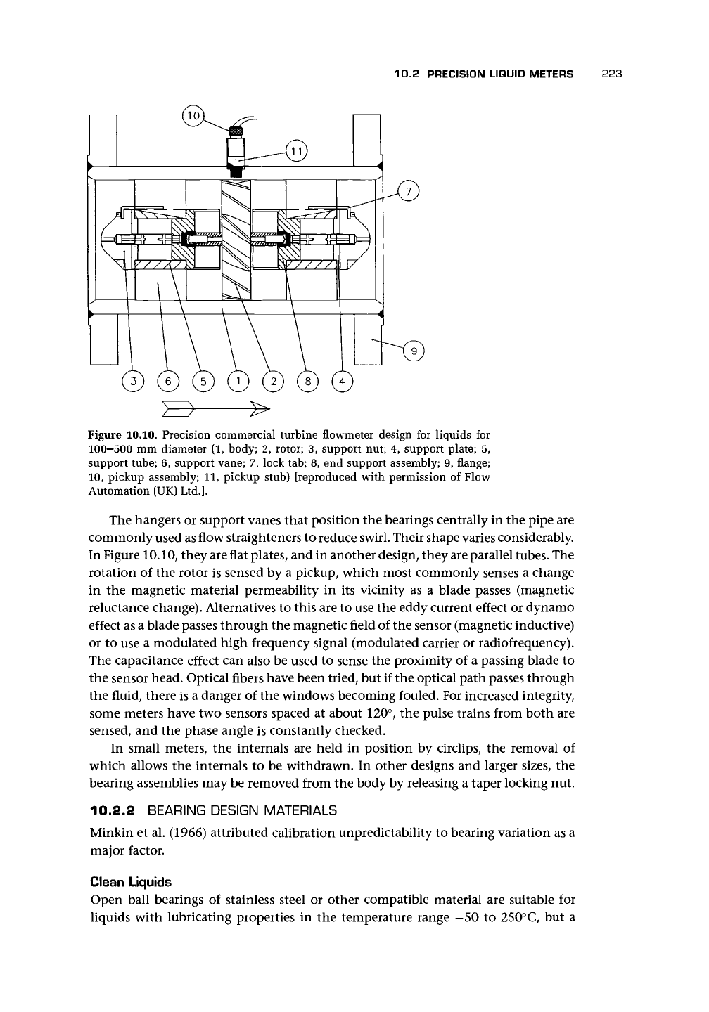
Figure 10.10. Precision commercial turbine flowmeter design for liquids for
100—500 mm diameter (1, body; 2, rotor; 3, support nut; 4, support plate; 5,
support tube; 6, support vane; 7, lock tab; 8, end support assembly; 9, flange;
10,
pickup assembly; 11, pickup stub) [reproduced with permission of Flow
Automation (UK)
Ltd.].
The hangers or support vanes that position the bearings centrally in the pipe are
commonly used as flow straighteners to reduce swirl. Their shape varies considerably.
In Figure 10.10, they are flat plates, and in another design, they are parallel
tubes.
The
rotation of the rotor is sensed by a pickup, which most commonly senses a change
in the magnetic material permeability in its vicinity as a blade passes (magnetic
reluctance change). Alternatives to this are to use the eddy current effect or dynamo
effect as a blade passes through the magnetic field of the sensor (magnetic inductive)
or to use a modulated high frequency signal (modulated carrier or radiofrequency).
The capacitance effect can also be used to sense the proximity of a passing blade to
the sensor head. Optical fibers have been tried, but if the optical path passes through
the fluid, there is a danger of the windows becoming fouled. For increased integrity,
some meters have two sensors spaced at about 120°, the pulse trains from both are
sensed, and the phase angle is constantly checked.
In small meters, the internals are held in position by circlips, the removal of
which allows the internals to be withdrawn. In other designs and larger sizes, the
bearing assemblies may be removed from the body by releasing a taper locking nut.
10.2.2 BEARING DESIGN MATERIALS
Minkin et al. (1966) attributed calibration unpredictability to bearing variation as a
major factor.
Clean Liquids
Open ball bearings of stainless steel or other compatible material are suitable for
liquids with lubricating properties in the temperature range -50 to 250°C, but a
224 TURBINE AND RELATED FLOWMETERS
filter with a mesh size small enough to prevent solid particle ingress into the bearings
should be used.
Liquids in General
Tungsten carbide or high chrome/high cobalt journal bearings possibly with carbide
pinions and a stellite sleeve are suitable in the range —50 to 400°C unlubricated.
The bearings are lubricated by the metered fluid and made up of tungsten carbide
with a hardness of Rockwell C-94 and a surface smoothness of 0.05 /xm. Tungsten
carbide with cobalt bonding is most common, but the cobalt is leached out by acidic
solutions used for cleaning. Stellite may then be used as a less durable alternative
for more corrosive fluids.
A
more recent alternative is nickel-bonded carbide bushes
with titanium carbide shafts. An alternative design uses rotor pins of hard metal in
sapphire bearings with thrust plate and rings made with curved contact surfaces for
line contact. Polytetrafluoroethylene (PTFE) is used in some applications. Ceramic
bearings (e.g., A1
2
O
3
), may also be an option.
One manufacturer has used a ball-and-sleeve design. The shaft was tipped with
an ellipsoid and ran in a ceramic sleeve so that line contact was achieved. Typi-
cal bearing life was claimed as 12-24 months when used with 50-75% duty cy-
cle in clean particulate-free gasoline. For ball race bearings correctly lubricated, a
life of 4,000-6,000 hours was claimed, and for journal bearings 20,000 hours or
more was claimed, depending upon the properties of the measured fluid and rate of
flow.
For some larger sizes (above about 80 mm) only an upstream bearing is used; it
consists of a tungsten carbide (or other suitable materials) bush and shaft. Special
bearings are available for cryogenic applications (cf. Rivetti et al. 1987). Hydrostatic
bearings may be suitable for dirty fluids. House and Johnson (1986) applied hydro-
static bearings and obtained a remarkable performance (turndown ratio for water
of
1,000:1)
and suitability for dirty fluids. Wemyss and Wemyss (1975) described
the development of the Hoverflo bearingless meter. Some manufacturers provide
application charts.
Ball bearings have been found satisfactory for cryogenic applications in rocket
testing because of their ability to tolerate overspeed and operation with
gas.
However,
journal bearings, although less linear, may be more repeatable.
10.2.3 STRAINERS
Typical values for strainers are given by manufacturers with maximum allowable
particulate sizes (Table 10.1).
10.2.4 MATERIALS
Because the signal is usually obtained from magnetic sensing, it is common to make
the tube of austenitic stainless steel to allow the magnetic field to penetrate. How-
ever, carbon steel is used for flanges and sometimes also for the bodies; in this in-
stance, provision is made for the pickup assembly to function despite the magnetic
body.
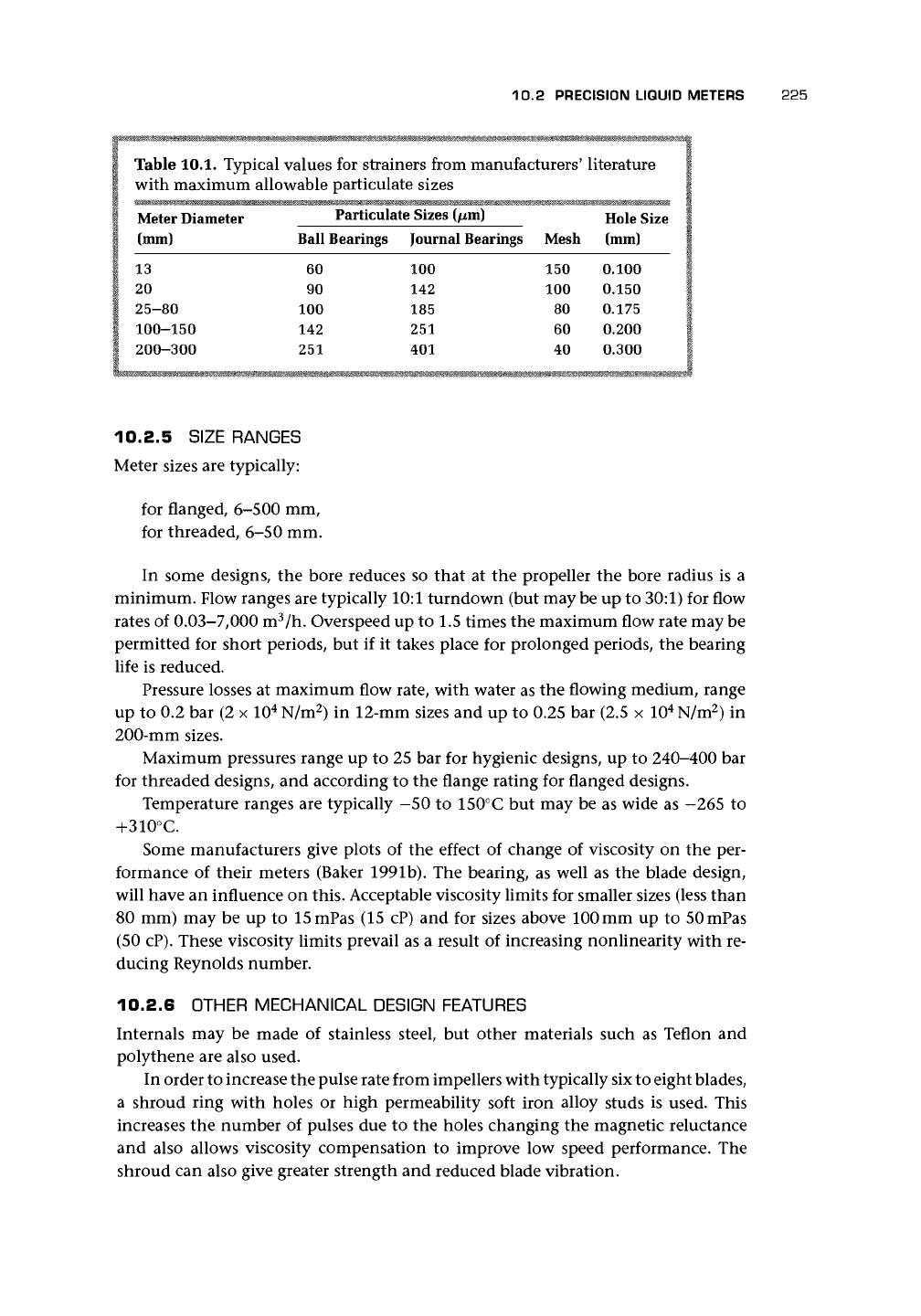
10.2 PRECISION LIQUID METERS 225
Table 10.1. Typical values for strainers from manufacturers' literature
with maximum allowable particulate sizes
Meter Diameter
(mm)
13
20
25-80
100-150
200-300
rariicuia
Ball Bearings
60
90
100
142
251
ie sizes t/xmj
Journal Bearings
100
142
185
251
401
Mesh
150
100
80
60
40
Hole Size
(mm)
0.100
0.150
0.175
0.200
0.300
10.2.5
SIZE RANGES
Meter sizes are typically:
for flanged, 6-500 mm,
for threaded, 6-50 mm.
In some designs, the bore reduces so that at the propeller the bore radius is a
minimum. Flow ranges are typically 10:1 turndown (but may be up to 30:1) for flow
rates of 0.03-7,000 m
3
/h. Overspeed up to 1.5 times the maximum flow rate may be
permitted for short periods, but if it takes place for prolonged periods, the bearing
life is reduced.
Pressure losses at maximum flow rate, with water as the flowing medium, range
up to 0.2 bar (2 x 10
4
N/m
2
) in 12-mm sizes and up to 0.25 bar (2.5 x 10
4
N/m
2
) in
200-mm sizes.
Maximum pressures range up to 25 bar for hygienic designs, up to 240-400 bar
for threaded designs, and according to the flange rating for flanged designs.
Temperature ranges are typically -50 to 150°C but may be as wide as -265 to
+310°C.
Some manufacturers give plots of the effect of change of viscosity on the per-
formance of their meters (Baker 1991b). The bearing, as well as the blade design,
will have an influence on this. Acceptable viscosity limits for smaller sizes (less than
80 mm) may be up to 15mPas (15 cP) and for sizes above 100 mm up to 50mPas
(50 cP). These viscosity limits prevail as a result of increasing nonlinearity with re-
ducing Reynolds number.
10.2.6 OTHER MECHANICAL DESIGN FEATURES
Internals may be made of stainless steel, but other materials such as Teflon and
polythene are also used.
In order to increase the pulse rate from impellers with typically six to eight blades,
a shroud ring with holes or high permeability soft iron alloy studs is used. This
increases the number of pulses due to the holes changing the magnetic reluctance
and also allows viscosity compensation to improve low speed performance. The
shroud can also give greater strength and reduced blade vibration.
226 TURBINE AND RELATED FLOWMETERS
In some small designs of turbine meter, the blades have a T shape so that at the
tip they are longer (longer chord) than at the hub. One reason given for this is to
improve insensitivity to viscosity change, which may result from a greater driving
torque achieved by increasing the blade lift at the maximum radius. It may also
flatten the characteristic hump at low speed. I am not aware of published data to
confirm these tendencies.
Some designs can be used bidirectionally, but, of course, they require calibration
in each direction.
Response time constants measured with water or with a liquid of similar density
range from 0.005 to 0.05 s for a 50% flow rate change or up to 0.17 s to reach 63%
of a step change final value.
After use with corrosive fluids, the meter should be cleaned with solvents. How-
ever, maximum rotational speeds should be carefully observed.
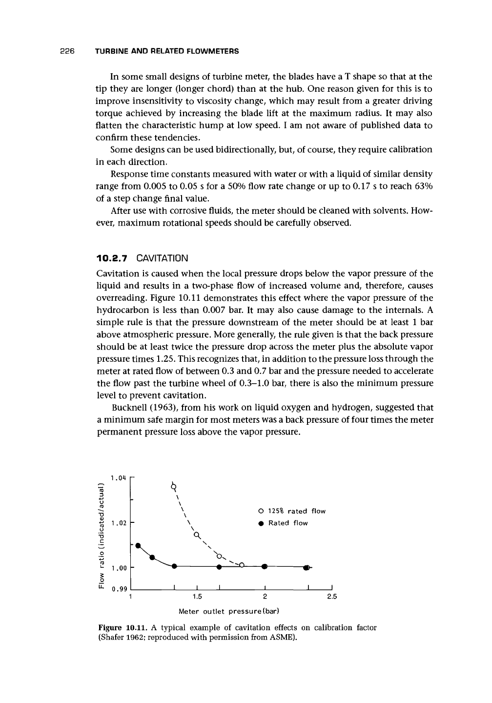
10.2.7 CAVITATI0N
Cavitation is caused when the local pressure drops below the vapor pressure of the
liquid and results in a two-phase flow of increased volume and, therefore, causes
overreading. Figure 10.11 demonstrates this effect where the vapor pressure of the
hydrocarbon is less than 0.007 bar. It may also cause damage to the internals. A
simple rule is that the pressure downstream of the meter should be at least 1 bar
above atmospheric pressure. More generally, the rule given is that the back pressure
should be at least twice the pressure drop across the meter plus the absolute vapor
pressure times 1.25. This recognizes that, in addition to the pressure loss through the
meter at rated flow of between 0.3 and 0.7 bar and the pressure needed to accelerate
the flow past the turbine wheel of 0.3-1.0 bar, there is also the minimum pressure
level to prevent cavitation.
Bucknell (1963), from his work on liquid oxygen and hydrogen, suggested that
a minimum safe margin for most meters was a back pressure of four times the meter
permanent pressure loss above the vapor pressure.
1.04
S
1-02
O
u
1.00
^ 0.99
\
\
x
x
O 125% rated flow
\ • Rated flow
\
J I I
1 1.5 2 2.5
Meter outlet pressure (bar)
Figure
10.11.
A typical example of cavitation effects on calibration factor
(Shafer 1962; reproduced with permission from ASME).