Baker R.C. Flow Measurement Handbook: Industrial Designs, Operating Principles, Performance, and Applications
Подождите немного. Документ загружается.

9.A.1 FLOWMETER EQUATION 207
The successful use of positive displacement meters in such a hostile environment
as oil-well flows suggests that other difficult applications may be within range.
Total blockage of the line in the event of failure is, perhaps, the greatest disad-
vantage, and ways of dealing with this through an automatically controlled bypass,
in the event of blockage, may overcome this problem.
APPENDIX
9.A
Theory for a Sliding Vane Meter
The theory of the meter was set out by Hahn (1968). In his paper he considered the
motion of the vanes and calculated the radial velocity and acceleration if the internal
controlling cam gave a sinusoidal motion. He noted that the resultant forces between
vane and wall contributed to the wear of the vanes. Avoidance of jerky motion and
shock stresses is clearly important.
He also calculated the volumetric flow rate (cf. Baker and Morris 1985 whose work
was in ignorance of that due to Hahn). Hahn pointed out that the radial motion of
the vanes results in a sinusoidal fluctuation superimposed on the volume versus
rotation characteristic and that the amplitude of this fluctuation can be of order
0.05-0.1%
for various designs. This, in turn, would be shown in an irregularity
of the rotation of the shaft of as much as
1.25%.
However, in practice there will
be a balance between varying flow, pressure variation, and rotor velocity variation.
Hahn also gave characteristics showing variation of within 0.2% over a range of 14:1
(slight drop of
1.5-2%
with increasing flow) and changes of +0.15% for a change in
viscosity from 0.75 to 4 cP.
9.A.1 FLOWMETER EQUATION
The ideal behavior of the meter is given by the product of transferred volume, the
number of volumes transferred per revolution, and the rotational speed. For the ac-
tual behavior allowance has to be made for the leakage that takes place past the mov-
ing rotors. The bulk volumetric flow for a meter of the sliding vane type is given by
q
y
= [n (r
0
2
- rf) -
8]
Nl
ax
- Leakage flow (9.A.I)
where £
ax
is the axial length of the chamber. The flow in each gap (Figure 9.A.I) will
be governed by
z
(9.A.2)
dy
where [i is the fluid velocity at y in the gap, t is the clearance, p
u
and pa are the
upstream and downstream pressures, L is the length of the clearance gap or, in the
case of the vanes, the thickness of the vanes, and
/JL
is the viscosity. This results in a
208 POSITIVE
DISPLACEMENT FLOWMETERS
,1
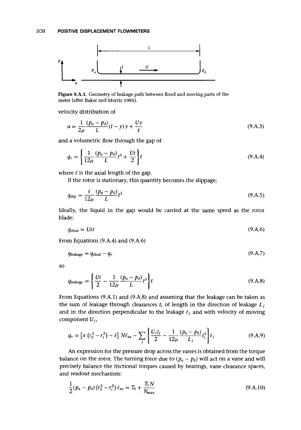
Figure
9.A.I. Geometry of
leakage
path between fixed and moving parts of the
meter
(after Baker and Morris 1985).
velocity
distribution of
u
= ^-i (t-
Uy
and
a
volumetric
flow through the gap of
1
(Ai - Pd)., Ut
(9.A.3)
(9.A.4)
where
I is the axial length of the gap.
If
the rotor is stationary, this quantity
becomes
the slippage;
(9.A.5)
Ideally,
the liquid in the gap would be carried at the same speed as the rotor
blade:
(9.A.6)
(9.A.7)
(9.A.8)
From Equations (9.A.I) and (9.A.8) and assuming that the leakage can be taken as
the sum of leakage through clearances tj of length in the direction of leakage L
;
and in the direction perpendicular to the leakage lj and with velocity of moving
component [/,-,
<?ideal
= Uti
From
Equations (9.A.4) and (9.A.6)
^leakage
= ^ideal — <?v
SO
\ut i (Pu-Pd)^
(9.A.9)
An expression for the pressure drop across the vanes is obtained from the torque
balance on the rotor. The turning force due to (p
u
- p
d
) will act on a vane and will
precisely balance the frictional torques caused by bearings, vane clearance spaces,
and readout mechanism:
(9.
A.
10)
9.A.2 EXPANSION OF THE FLOWMETER DUE TO TEMPERATURE 209
where 7o is a constant torque and
T\N/N
max
is a speed-dependent torque. Part of the
torque
TiN/N
max
will be due to the clearance drag torque:
where r
;
is the radius from the rotational axis of the ;th clearance.
9.A.2 EXPANSION OF THE FLOWMETER DUE TO TEMPERATURE
If a
m
is the coefficient of linear expansion of the metal, then a change in temperature
AT
m
of the metal of the flowmeter will cause a change in length
so that
^=3a
m
AT
m
(9.A.12)
giving the fractional change in measured volume per revolution of the flowmeter
rotor.
Differential Expansion
If the expansion of the rotor differs from that of the casing due either to different
temperatures or to different materials, then the clearances will be designed for the
greatest relative movement between these members. The change in the value of the
clearance t will be
-=a
m
AT
m
- (9.A.13)
between uniform temperature conditions and conditions when the temperature of
the internal rotor and the casing differ by A
7^.
For the case where the temperatures
are the same but the coefficients of expansion differ, this becomes
At r~
(9.A.14)
Liquid Density Change
The change in the bulk flow due to expansion of the liquid will be
(9.A.15)
where a
t
is the coefficient of volume expansion of the liquid.
Because many liquids are bought and sold by volume, this change is of
a
different
significance from those given before. The volume passed by the meter
may,
therefore,
be important. In some cases, the change in liquid density may be ignored.
210 POSITIVE DISPLACEMENT FLOW METERS
9.A.3 PRESSURE EFFECTS
Provided that the meter is supplied with an outer pressure vessel, there should be no
net pressure causing distortion of the inner meter. However, this is not invariably
so.
The meter will then suffer from two distortions, hoop stress and axial stress. For
convenience, we will consider these effects separately and ignore the effects of one
on the other.
Bulk Flow Error
If Ap is the difference between internal and external pressure and E is Young's mo-
dulus of elasticity, then the change in the outer radius will be
IT-IT
(9A16)
where £, is the thickness of the outer casing. The axial stress will cause an elongation
of
where £
ax
is the axial length of the meter's measuring chamber. Together these lead
(neglecting Poisson
;
s ratio effects) to an increase in measuring volume, which causes
an error in the volumetric flow rate of
Leakage Gap
In certain designs, the hoop stress will cause an increase in the clearance of
At
=
Arc
=
rjAp
t t ttoE
v ;
whereas the axial stress will cause an increase in end clearance at each end of
At A£
ax
r
o
4x Ap
t t
(9.A.20)
Clearly these calculations are simplifications of the actual expansion that will occur,
but they allow some estimate of likely errors to be made.
9.A.4 METER ORIENTATION
Bearings at Each End of Shaft
Assuming that the shaft behaves like a beam simply supported at each end and that
the rotor weight is evenly distributed along the shaft, then the maximum deflection
at the point midway between the bearings will be given by
Deflection =
SMgi
\ (9.A.21)
9.A.5 ANALYSIS OF CALIBRATORS
211
where
M is the
mass
of the
rotor,
g is
acceleration
due to
gravity,
and r
s
is
shaft
radius.
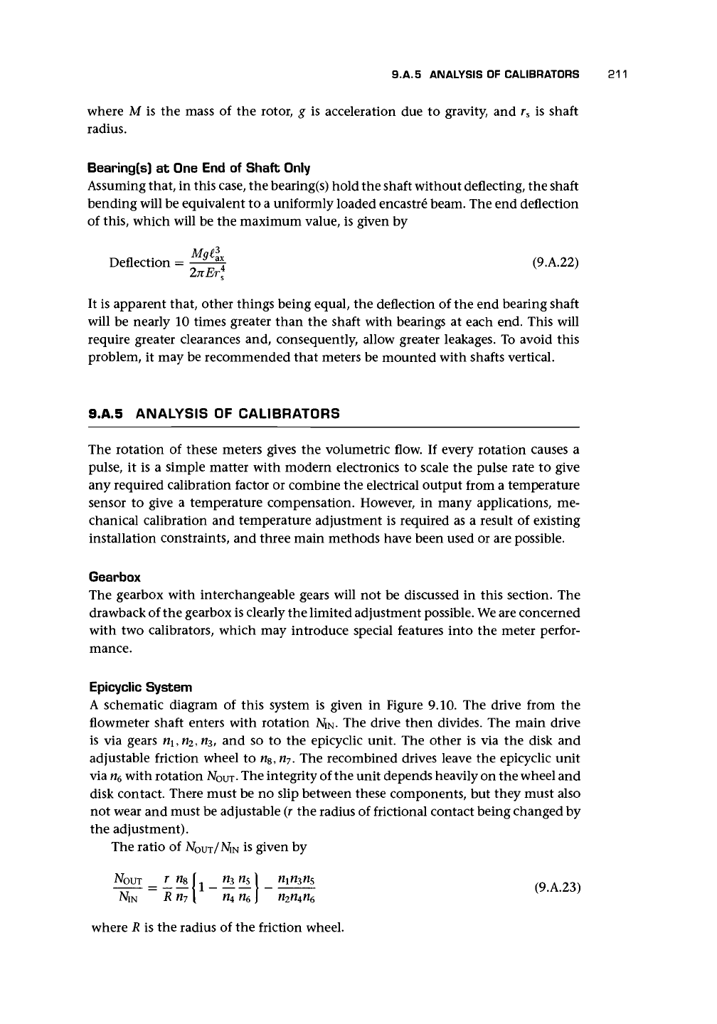
Bearing(s)
at
One End
of
Shaft Only
Assuming that,
in
this case, the bearing(s) hold the shaft without deflecting, the shaft
bending will be equivalent
to a
uniformly loaded encastre beam. The end deflection
of this, which will
be the
maximum value,
is
given
by
Mai
3
Deflection
=
y a
*
(9.A.22)
It
is
apparent that, other things being equal,
the
deflection
of
the end bearing shaft
will
be
nearly
10
times greater than
the
shaft with bearings
at
each end. This will
require greater clearances
and,
consequently, allow greater leakages.
To
avoid this
problem,
it
may be recommended that meters
be
mounted with shafts vertical.
9.A.5 ANALYSIS
OF
CALIBRATORS
The rotation
of
these meters gives
the
volumetric flow.
If
every rotation causes
a
pulse,
it is a
simple matter with modern electronics
to
scale
the
pulse rate
to
give
any required calibration factor
or
combine
the
electrical output from
a
temperature
sensor
to
give
a
temperature compensation. However,
in
many applications,
me-
chanical calibration
and
temperature adjustment
is
required
as a
result
of
existing
installation constraints,
and
three main methods have been used
or
are possible.
Gearbox
The gearbox with interchangeable gears will
not be
discussed
in
this section.
The
drawback of the gearbox is clearly the limited adjustment possible. We are concerned
with
two
calibrators, which
may
introduce special features into
the
meter perfor-
mance.
Epicyclic System
A schematic diagram
of
this system
is
given
in
Figure
9.10. The
drive from
the
flowmeter shaft enters with rotation 2V
IN
.
The
drive then divides.
The
main drive
is
via
gears tt\, n
2
, n
3
,
and so to the
epicyclic unit.
The
other
is via the
disk
and
adjustable friction wheel
to
n
s
,n
7
.
The
recombined drives leave
the
epicyclic unit
via n
6
with rotation
A/OUT-
The integrity of the unit depends heavily on the wheel and
disk contact. There must
be no
slip between these components,
but
they must also
not wear and must be adjustable
(r
the radius
of
frictional contact being changed by
the adjustment).
The ratio
of
N
O
UT/MN is given by
NOUT
^L ffcWs
1
rnn
3
ns
NIM
Rn
7
[
n
4
n
6
\ n
2
n
4
n
6
where
R is the
radius
of
the friction wheel.
212 POSITIVE DISPLACEMENT FLOWMETERS
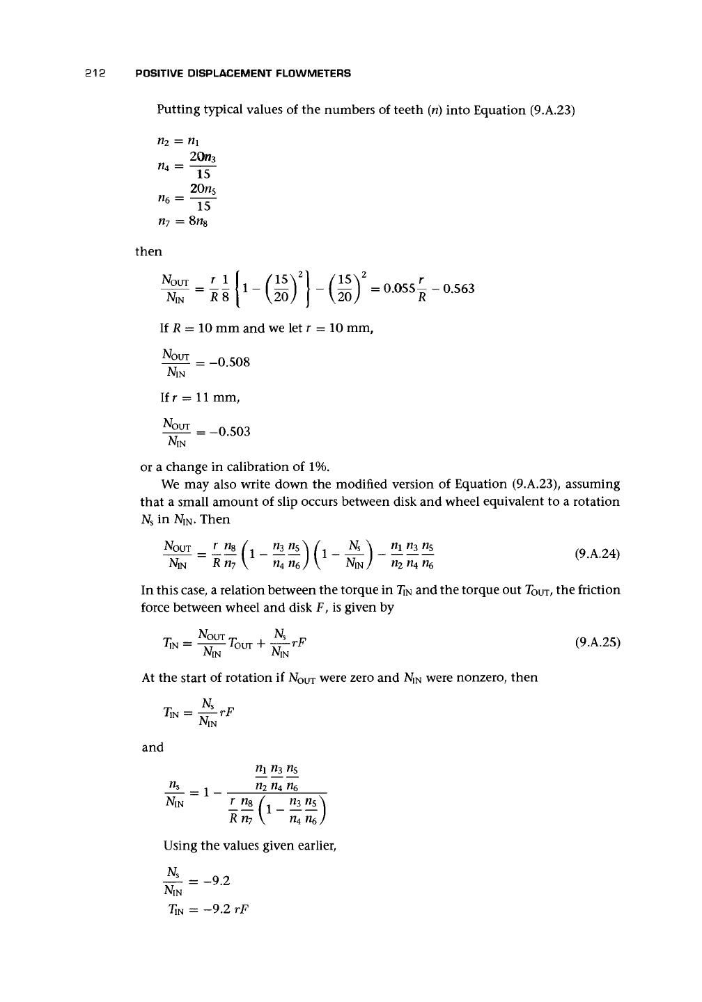
Putting typical values of the numbers of teeth
(ri)
into Equation (9.A.23)
n
2
= rii
n
4
=
n
6
=
15
20n
5
~15~
n
7
= Sn
8
then
NQUT
If
JR
= 10 mm and we let r = 10 mm,
^^ = -0.508
Ifr = 11 mm,
1ST
=
-°-
503
or a change in calibration of 1%.
We may also write down the modified version of Equation (9.A.23), assuming
that a small amount of slip occurs between disk and wheel equivalent to a rotation
N
s
in
NIN.
Then
K™ = L
n
A d _
Hi!!*]
(i-**L\- ^^
(9.A.24)
N
IN
R n
7
\ n
4
n
6
j \ N
iN
) n
2
n
4
n
6
In this case, a relation between the torque in Ti
N
and the torque out T
O
m, the friction
force between wheel and disk F, is given by
(9.A.25)
At the start of rotation if N
O
UT were zero and Ni
N
were nonzero, then
NIN
and
n
2
n
4
n
6
= 1-
R n
7
V n
4
n
6
Using the values given earlier,
—5-
= -9.2
T
lN
= -9.2 rF
9.A.6 APPLICATION OF EQUATIONS TO A TYPICAL METER 213
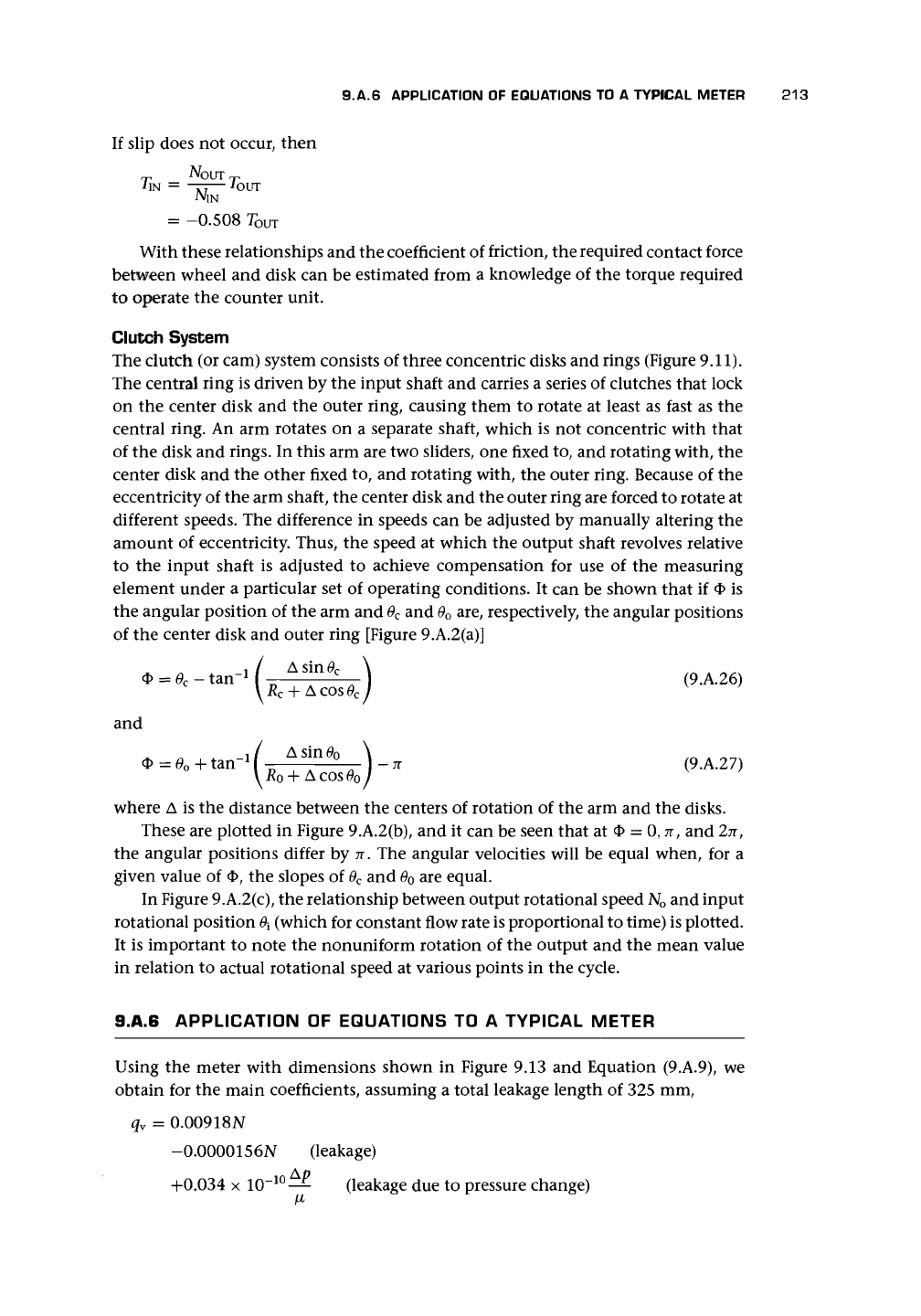
If slip does not occur, then
NOUT rj,
iiN = —j^— -four
NIN
=
-0.508
TOUT
With these relationships and the coefficient of friction, the required contact force
between wheel and disk can be estimated from a knowledge of the torque required
to operate the counter unit.
Clutch System
The clutch (or cam) system consists of three concentric disks and rings (Figure 9.11).
The central ring is driven by the input shaft and carries a series of clutches that lock
on the center disk and the outer ring, causing them to rotate at least as fast as the
central ring. An arm rotates on a separate shaft, which is not concentric with that
of the disk and rings. In this arm are two sliders, one fixed to, and rotating with, the
center disk and the other fixed to, and rotating with, the outer ring. Because of the
eccentricity of the arm shaft, the center disk and the outer ring are forced to rotate at
different speeds. The difference in speeds can be adjusted by manually altering the
amount of eccentricity. Thus, the speed at which the output shaft revolves relative
to the input shaft is adjusted to achieve compensation for use of the measuring
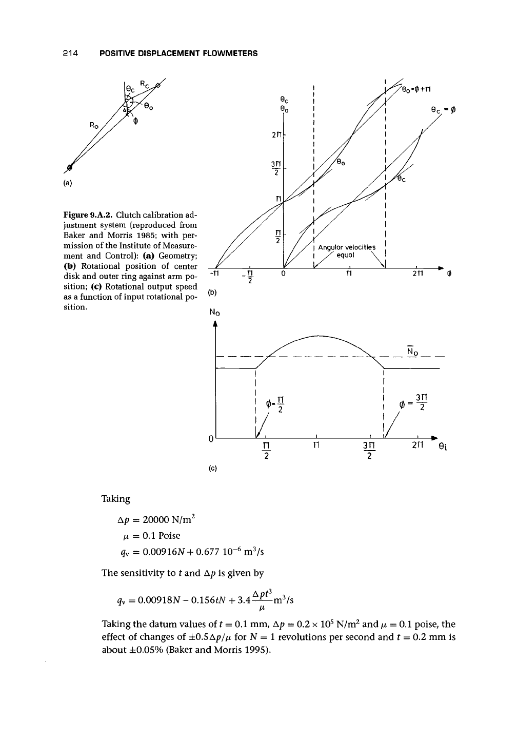
element under a particular set of operating conditions. It can be shown that if O is
the angular position of the arm and
0
c
and
0
o
are, respectively, the angular positions
of the center disk and outer ring [Figure 9.A.2(a)]
f
p
)
(9.A.26)
and
* =
0
o
+ tan"
1
(
A
f
e
\) -
* (9.A.27)
y^
+
Acos^/
where A is the distance between the centers of rotation of the arm and the disks.
These are plotted in Figure 9.A.2(b), and it can be seen that at
<J>
= 0, n, and 2n
f
the angular positions differ by n. The angular velocities will be equal when, for a
given value of $, the slopes of
6
C
and 0
0
are equal.
In Figure 9.A.2(c), the relationship between output rotational speed N
o
and input
rotational position
0
x
(which for constant flow rate is proportional to time) is plotted.
It is important to note the nonuniform rotation of the output and the mean value
in relation to actual rotational speed at various points in the cycle.
9.A.6 APPLICATION OF EQUATIONS TO A TYPICAL METER
Using the meter with dimensions shown in Figure 9.13 and Equation (9.A.9), we
obtain for the main coefficients, assuming a total leakage length of 325 mm,
q
v
= 0.00918N
-0.0000156N (leakage)
+0.034 x
10~
10
—
(leakage due to pressure change)
214
POSITIVE DISPLACEMENT FLOWMETERS
Figure 9.A.2. Clutch calibration ad-
justment system (reproduced from
Baker
and
Morris 1985; with
per-
mission
of
the Institute
of
Measure-
ment
and
Control):
(a)
Geometry;
(b) Rotational position
of
center
disk
and
outer ring against arm po-
sition;
(c)
Rotational output speed
as
a
function
of
input rotational po-
sition.
No
/
1
1
I
!/
1/.
^\
N
o
\
1
I
1
i
0
=
T
/
,
!/ , .
2
n
3Tt
2
2T1
(c)
Taking
Ap = 20000 N/m
2
[i = 0.1 Poise
q
v
= 0.00916N + 0.677 10~
6
m
3
/s
The sensitivity to t and Ap is given by
q
v
= 0.00918N - 0.156tN + 3
Taking the datum values of t = 0.1 mm, Ap = 0.2 x 10
5
N/m
2
and /x = 0.1 poise, the
effect of changes of ±0.5Ap//x for N = 1 revolutions per second and t = 0.2 mm is
about ±0.05% (Baker and Morris 1995).
CHAPTER
1O
Turbine
and
Related Flowmeters
10.1 INTRODUCTION
10.1.1
BACKGROUND
Spirals, screws,
and
windmills have
a
long history
of use for
speed measurement.
Robert Hook proposed
a
small windmill
in
1681
for
measuring air velocity
and
later
one
for use as a
ship's
log
(distance meter).
A
Captain Phipps,
in
1773, created
a
ship's
log,
using
the
principle that
a
spiral,
in
turning, moves through
the
length
of
one
turn
of the
spiral. Many centuries earlier,
it
appears that
a
Roman architect,
Vitruvius, suggested
a
more basic form
of
this device.
In 1870 Reinhard Woltmann developed
a
multibladed
fan to
measure river flows
(Medlock 1986).
The
device
was a
forerunner
of the
long helical screw-type meter
still called after
him and
used widely
for
pipe flows
in the
water industry.
The
first
modern meters,
of
the type with which we are mainly concerned, were developed
in
the United States
in 1938
(Watson
and
Furness 1977;
cf.
Furness 1982). These were
attractive
for
fuel flow measurement
in
airborne applications. They consisted
of a
helically bladed rotor
and
simple bearings. Improved sleeve bearings were developed
for longer life with hardened thrust balls
or
endstones
to
withstand
the
axial load.
An alternative, developed over several years
and
patented
by
Potter (1961),
was to
profile
the hub of
the rotor
so
that
the
pressure balance across
the
rotor, rather than
the thrust
on the
bearings, held
it
against
the
axial drag forces. This allowed
the
rotor
to run on a
single journal bearing.
10.1.2
QUALITATIVE DESCRIPTION
OF
OPERATION
The turbine consists
of a
bladed rotor that turns
due to the
flow
in the
pipe.
In
most
of the
designs
to be
discussed,
the
rotor
is
designed
to
create
the
minimum
disturbance
as the
oncoming flow passes around it. Ideally,
it
cuts perfectly through
the fluid
in a
helix
so
that every revolution
of the
helix represents
one
complete
axial length
of the
screw,
and
hence
a
calculable volume
of the
fluid.
In
practice,
there
are
drag forces, which slightly retard
the
rotation. These result from frictional
drag
on the
blades,
the
hub,
the
faces
of
the rotor,
and the tip of
the blades; bearing
drag, also
a
frictional effect;
and
drag
due to the
means
by
which
the
rotation
is
measured, which
is
usually
a
magnetic drag. These drag forces affect
the
otherwise
ideal relationship
of
constant fluid volume
for
each rotor revolution
and
lead
to
nonlinearity.
215
216
TURBINE AND RELATED FLOWMETERS
The rotor has to be held in the stream, and so supports are invariably necessary
to position the bearings centrally in the pipe. Virtue is made of necessity, and these
supports are used to provide some flow straightening, since the turbine meter is of a
type particularly susceptible to swirl. The oncoming fluid will therefore need to flow
over the upstream support, and the naturally occurring profile, where the velocity of
the fluid is lower at the pipe wall than at the center of the pipe, will be redistributed
into the annular passage past the
blades,
and, perhaps most importantly, there will be
a reduction in any swirl component due both to conservation of angular momentum
during the redistribution and to the straightening effect of the supports. The velocity
in this passage will vary a small amount with radial position, and a well-designed
turbine rotor will generally have helical blades to match the axial and tangential
velocity of the rotor at each radial position.
The main variants from this description are the Pelton and vane or paddle wheel
designs. In the former, a tangential jet of fluid hits the buckets or blades of the wheel
and causes them to rotate. This design has two alternative virtues: it can be made
as a simple insertion probe to obtain an estimate of the flow rate, or it can be used
in very small flows to register where other designs fail. Other designs using larger
paddle wheels and angled propellers are also available (cf. Baker 1991b, 1993).
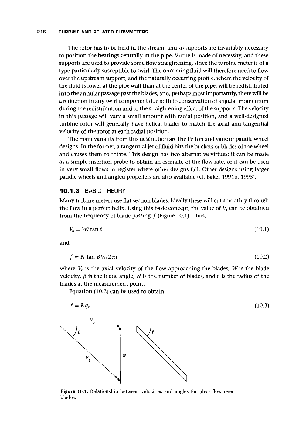
10.1.3 BASIC THEORY
Many turbine meters use flat section blades. Ideally these will cut smoothly through
the flow in a perfect helix. Using this basic concept, the value of
V
z
can be obtained
from the frequency of blade passing f (Figure 10.1). Thus,
=
W/t<m/3
and
f=N tan
(10.1)
(10.2)
where V
z
is the axial velocity of the flow approaching the blades, W is the blade
velocity,
f5
is the blade angle, N is the number of blades, and r is the radius of the
blades at the measurement point.
Equation (10.2) can be used to obtain
f=Kq
v
(10.3)
Figure 10.1. Relationship between velocities and angles for ideal flow over
blades.