Baker R.C. Flow Measurement Handbook: Industrial Designs, Operating Principles, Performance, and Applications
Подождите немного. Документ загружается.

10.3 PRECISION GAS METERS
237
1000
a 61 bar
nat. gas
2000
flow rate (m3/h)
+ 7.8 bar
nat. gas
3000 4000
1.0 bar
(a)
b
UJ
-0.20
-0.40
-0.60
0.01
Reynolds nurrber (10*6)
61 bar + 7.8 bar • 1.0 bar
nat. gas nat. gas air
(b)
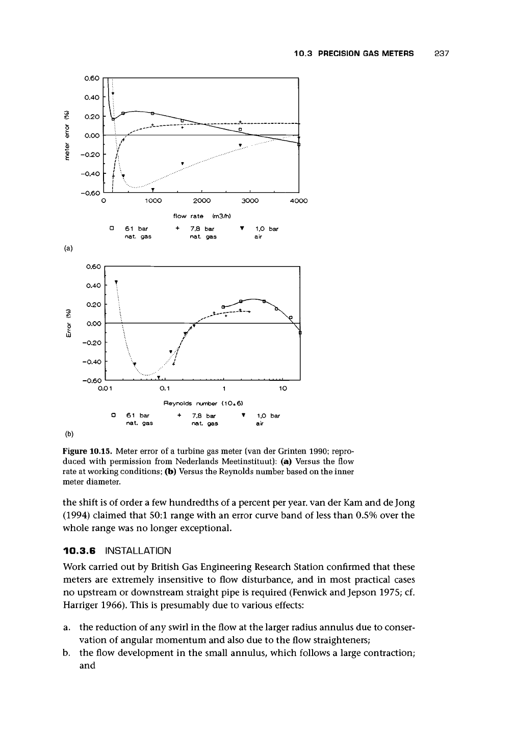
Figure 10.15. Meter error of a turbine gas meter (van der Grinten 1990; repro-
duced with permission from Nederlands Meetinstituut): (a) Versus the flow
rate at working conditions; (b) Versus the Reynolds number based on the inner
meter diameter.
the shift is of order a few hundredths of a percent per year, van der Kam and
de
Jong
(1994) claimed that 50:1 range with an error curve band of less than 0.5% over the
whole range was no longer exceptional.
10.3.6 INSTALLATION
Work carried out by British Gas Engineering Research Station confirmed that these
meters are extremely insensitive to flow disturbance, and in most practical cases
no upstream or downstream straight pipe is required (Fenwick and Jepson 1975; cf.
Harriger 1966). This is presumably due to various effects:
a. the reduction of any swirl in the flow at the larger radius annulus due to conser-
vation of angular momentum and also due to the flow straighteners;
b.
the flow development in the small annulus, which follows a large contraction;
and
238 TURBINE AND RELATED FLOWMETERS
c. the integrating effect due to the linear relationship between lift coefficient and
incidence for small incidence angles.
They suggested that flow straighteners should only be used upstream if there is a
possibility of persistent swirling flow at inlet (cf. Mottram and Hutton 1987).
For inlet flow disturbance, van der Kam and Dam (1993) suggested that the inlet
flow conditioner could be quite effective in removing swirl, so that swirling flow from
a double elbow out-of-plane (with a 40° swirl angle) may not cause errors of more
than 0.3% (cf. Bellinga and Stronk 1974 on the development of a straightener). Also
change in pipe size before the meter is insignificant. In extreme cases, a tube bundle
may deal with the problem. Roughness does not affect performance. Temperature
effects are small for a 20° C variation but are difficult to examine due to the lack of a
suitable rig. The turbine meter is not suitable for wet or dirty flows. Gases should be
clean and free of liquids and dust; otherwise, a filter with 5-/xm filtration quality or
better should be used. The upstream pipework should be cleaned before installing
the meter (cf. Bonner 1993 and ISO 9951).
According to Harriger (1966), a short-coupled installation with as little as 4D
upstream (2D straightener and 2D straight pipe) is allowable. However, swirl and
pulsation can cause significant errors. Meters have
a
built-in flow straightener, which
removes some of the swirl. Straightening vanes may be necessary if pipe fittings are
at 5D or less upstream. The meter should be carefully centered and protuberances
should be avoided for at least 5D upstream. Downstream the pipework should be full
bore,
but no other restrictions are placed on it. van der Kam and van Dellen (1991)
for a 300-mm gas turbine meter suggested that 10D upstream length was sufficient
to keep the meter within the limits allowed and 15D if swirl was present.
Excessive speeds can damage the meter, but 20% excess may be allowable for
short periods.
Temperature should be measured downstream within 2D. One manufacturer
gives a temperature range of -10 to 50°C.
If, as a result of changes in the process conditions, liquid condensate is produced
in the pipework, means of drainage should be provided.
10.3.7 SENSING
The alternative means of measuring the rotation of the wheel are the mechanical
system involving a gear train, which can result in retarding forces due to gear losses,
losses in the magnetic coupling, and loads from the meter register and calibration
adjustment, or the electromagnetic design in which the loads are much reduced.
For a high frequency signal, a proximity switch operating off the aluminum blades,
metal strips contained in the hub, or a follower disk on the main shaft, with magnetic
probe or proximity switch, allow up to 3 kHz. For low frequencies of 1-10 pulses per
revolution, a reed switch or slot sensor are used.
10.3.8 UNSTEADY FLOW
The gas turbine meter is affected by varying or pulsating flows. The increasing flow
creates higher incidence angles on the turbine blades, and the turbine wheel accel-
erates fast. However, when the flow decreases, the blades presumably stall with low
10.3 PRECISION GAS METERS 239
3
I
Q
a.
§
o
ROTOR SPEED DECAY TIME-t
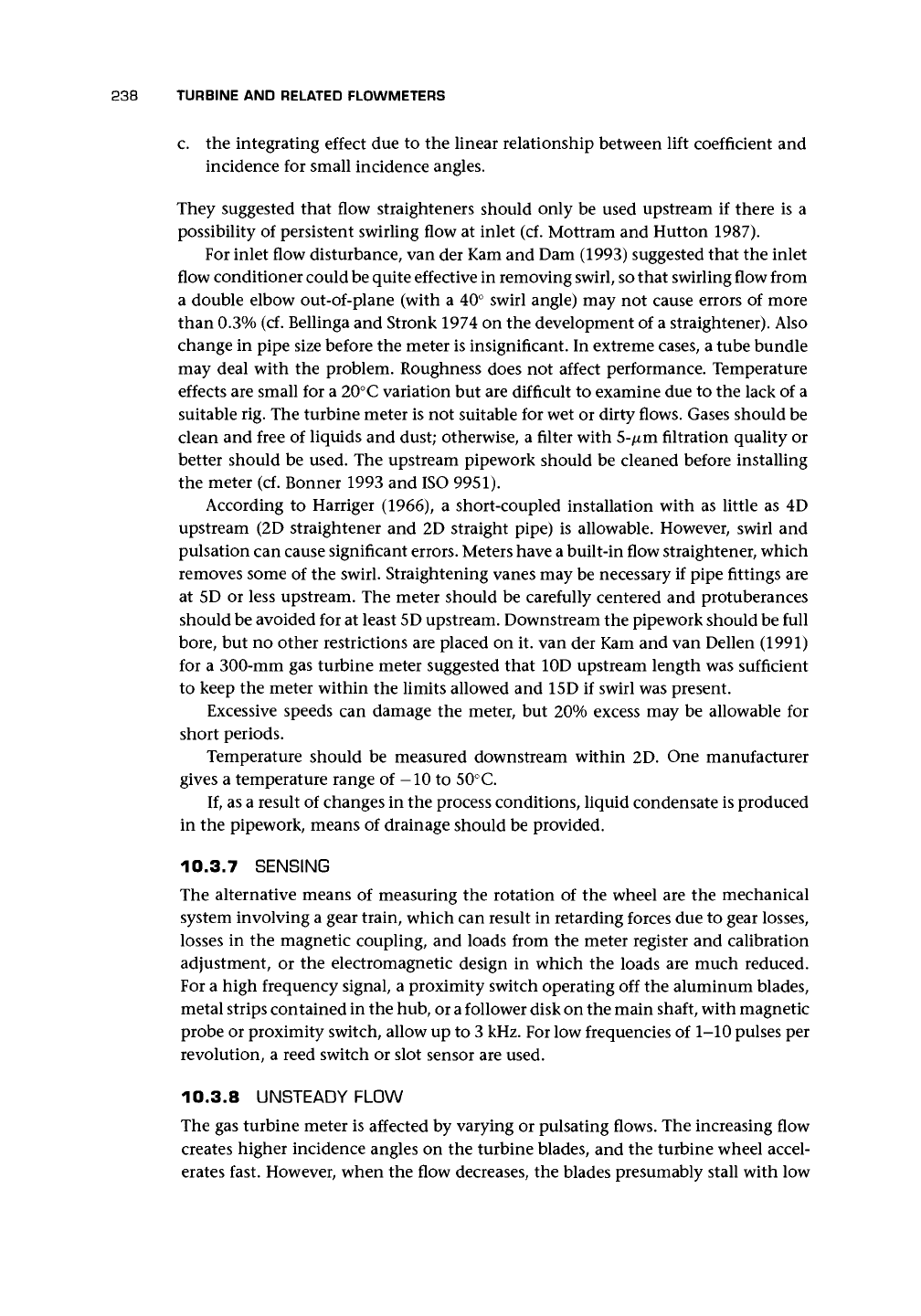
Figure 10.16. Rotor speed decay curve for no flow [Equation
(10.
A..
20)]
of
a
given
meter during coasting process of the spin test (Lee and Evans 1970; reproduced
with permission from ASME).
retarding force and hence low deceleration. The effect is to give an overestimation of
the total flow. The turbine bearings may be damaged if subject to fluctuating flows
for extended periods. Head (1956) gave a pulsation factor, which for turbine meters
was
^ =
(l+abF
2
)
(10.8)
qv
where q
x
is the indicated flow rate, q
v
is the actual flow rate, a = | for sinusoidal
variation of flow, b is taken as unity for nonfollowing meters, and r is full flow
amplitude relative to average flow. Head gives r = 0.1 as the practical threshold for
significant error.
The transient analysis is given in Appendix 10.A.2. From this analysis, a speed
decay curve for no flow is obtainable (Figure 10.16). We can obtain from this curve
the rotor coast time to standstill and the final slope 5 of the curve, which is related
to the ratio of the nonfluid drag and the inertia and hence to the condition of the
bearings. However, de Jong and van der Kam (1993) were doubtful as to its value
for high pressures. The reader is also referred to the paper by Lee and Evans (1970)
who describe how they obtained speed of decay curves using an externally applied
mechanical friction loading method and also gave typical values of inertia (e.g., for
a 150-mm low pressure meter with plastic rotor / = 0.242 x 10~
3
kg m
2
and for a
high pressure meter with aluminum rotor / = 0.486 x 10~
3
kg m
2
). They also gave
rj
= 0.2 as used in Appendix 10.A.2.
Lee et al. (1975) obtained the effect of sinusoidal pulsation on errors. Assuming
the worst situation where rotor inertia is too great to follow pulsation, they obtained
for a pulsation index of 0.1 about 0.5% error and for 0.2 about 2% error where the
240 TURBINE AND RELATED FLOWMETERS
•4
' i
i
1
i
r
v
mean
•
Time
Experiment
O T =20S
A T =50S
D
T =360S
Theory
0.1 0.2 0.3 0.4 0.5 0.6 0.7 0.8 0.9
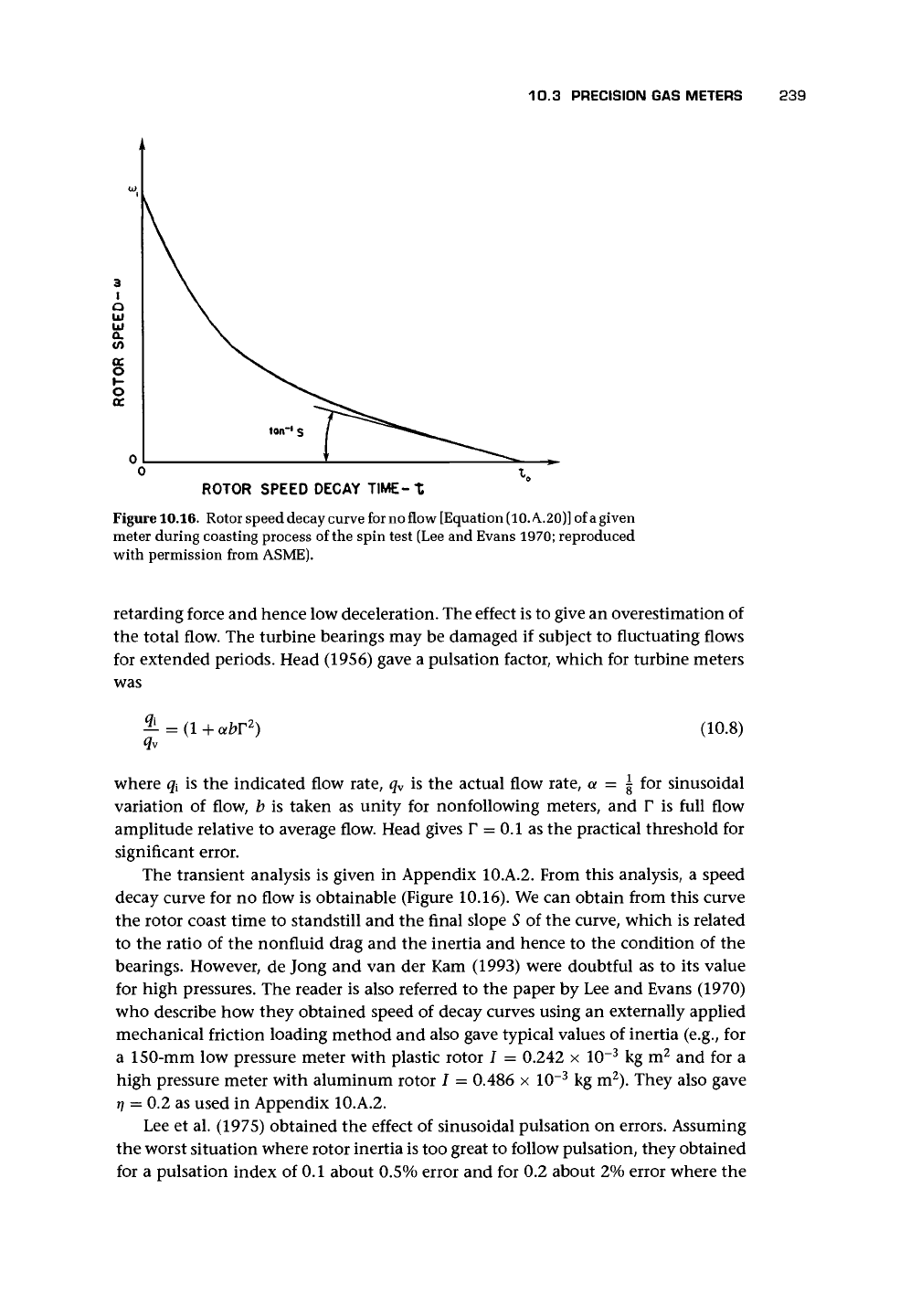
Figure 10.17. Effect of modulating flow on the performance of
a
4-in. (100-mm)
turbine meter (Fenwick and Jepson
1975;
reproduced with permission of British
Gas).
pulsation index is assumed to be given by
=
Vmax ~ ^min
V
max
+
V
min
Figure 10.17 is adapted from Fenwick and Jepson (1975) and shows the effect on
a turbine meter of a square wave pulsation. McKee (1992) found errors rising from
zero for a 2% variation to 1.5% for 6% and above (cf. Atkinson 1992 who developed
a computational analysis of the meter error for near-sinusoidal flow pulsations and
Cheesewright et al. 1996 who queried the lack of reports of flows with pulsating
waveforms).
Fenwick and Jepson (1975) gave as an example a 100-mm meter subjected
to on-off pulsations with a period of 60 s resulting in a 40% overregistration (cf.
Grenier 1991).
I worked with some data from tests where a gas conversion process required
variations in natural gas flows from high to low flow and back with sudden change
and significant errors, which were predicted by the methods of Jepson and others.
10.3.9 APPLICATIONS
One manufacturer claims that its meters can be used with all nonaggressive gases
and fuel gases including town gas, natural gas, refinery gas, coke-oven gas, propane,
butane, liquid gas/air mixtures, acetylene, ethane, nitrogen, carbon dioxide (dry),
air, and all inert gases.
It is unusual for the turbine meter to be applied to flows of oxygen for the fol-
lowing reasons.
a. Any lubricant used must be compatible with oxygen.
10.4 WATER METERS 241
b.
A maximum flow rate of order 10 m/s may be specified for oxygen flows in
pipework that may oxidize, and this tends to be rather low for a gas turbine
meter.
Pfrehm (1981) described a system adapted from long accepted and accurate liquid
measurement techniques to the mass measurement of ethylene gas. It consisted of
a meter, density measurement, flow computer, and piston bidirectional pipe prover.
The meter is claimed to provide accuracies of ±0.2% with linearity from 20% or less
to 100% of maximum flow.
10.3.10 ADVANTAGES AND DISADVANTAGES
Newcombe and Griffiths (1973) made the following suggestions.
a. Changes in friction and blade form due to mechanical deterioration or damage
reduces the meter's rangeability and gives a slow registration. Filtering limits the
rate of deterioration, but regular proving tests are required. Spin down tests can
indicate bearing deterioration.
b.
Rapid flow variations cause the meter to read fast. For a 10 minute off/10 minute
on cycle, one meter read 3% fast.
c. Swirl will affect registration unless a straightener is fitted.
d. Registration shifts between low and high pressure operation and, due to high
bearing friction, can be as large as 2%.
e. Security of gas flow is not affected if the meter fails.
To these, van der Kam et al. (1990) add reliability, high accuracy, dual measurement,
and back-up system in a device with proven technology.
10.4 WATER METERS
10.4.1 PRINCIPAL DESIGN COMPONENTS
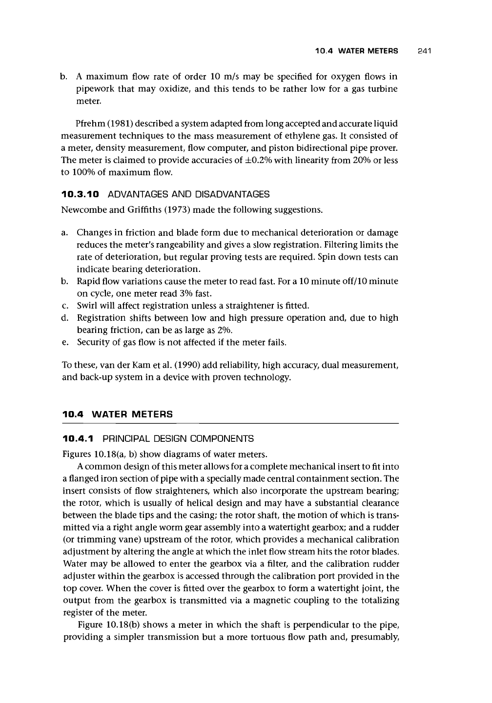
Figures 10.18(a, b) show diagrams of water meters.
A
common design of this meter allows for a complete mechanical insert to fit into
a flanged iron section of pipe with a specially made central containment section. The
insert consists of flow straighteners, which also incorporate the upstream bearing;
the rotor, which is usually of helical design and may have a substantial clearance
between the blade tips and the casing; the rotor shaft, the motion of which is trans-
mitted via a right angle worm gear assembly into a watertight gearbox; and a rudder
(or trimming vane) upstream of the rotor, which provides a mechanical calibration
adjustment by altering the angle at which the inlet flow stream hits the rotor blades.
Water may be allowed to enter the gearbox via a filter, and the calibration rudder
adjuster within the gearbox is accessed through the calibration port provided in the
top cover. When the cover is fitted over the gearbox to form a watertight joint, the
output from the gearbox is transmitted via a magnetic coupling to the totalizing
register of the meter.
Figure 10.18(b) shows a meter in which the shaft is perpendicular to the pipe,
providing a simpler transmission but a more tortuous flow path and, presumably,
242 TURBINE AND RELATED FLOWMETERS
Figure 10.18. Diagrams of water meters (reproduced with permission of
Meinecke):
(a) Gas and
Water Meter Manufacturers meter; (b) Gas and Water Meter Manufacturers meter with shaft
perpendicular to the pipe.
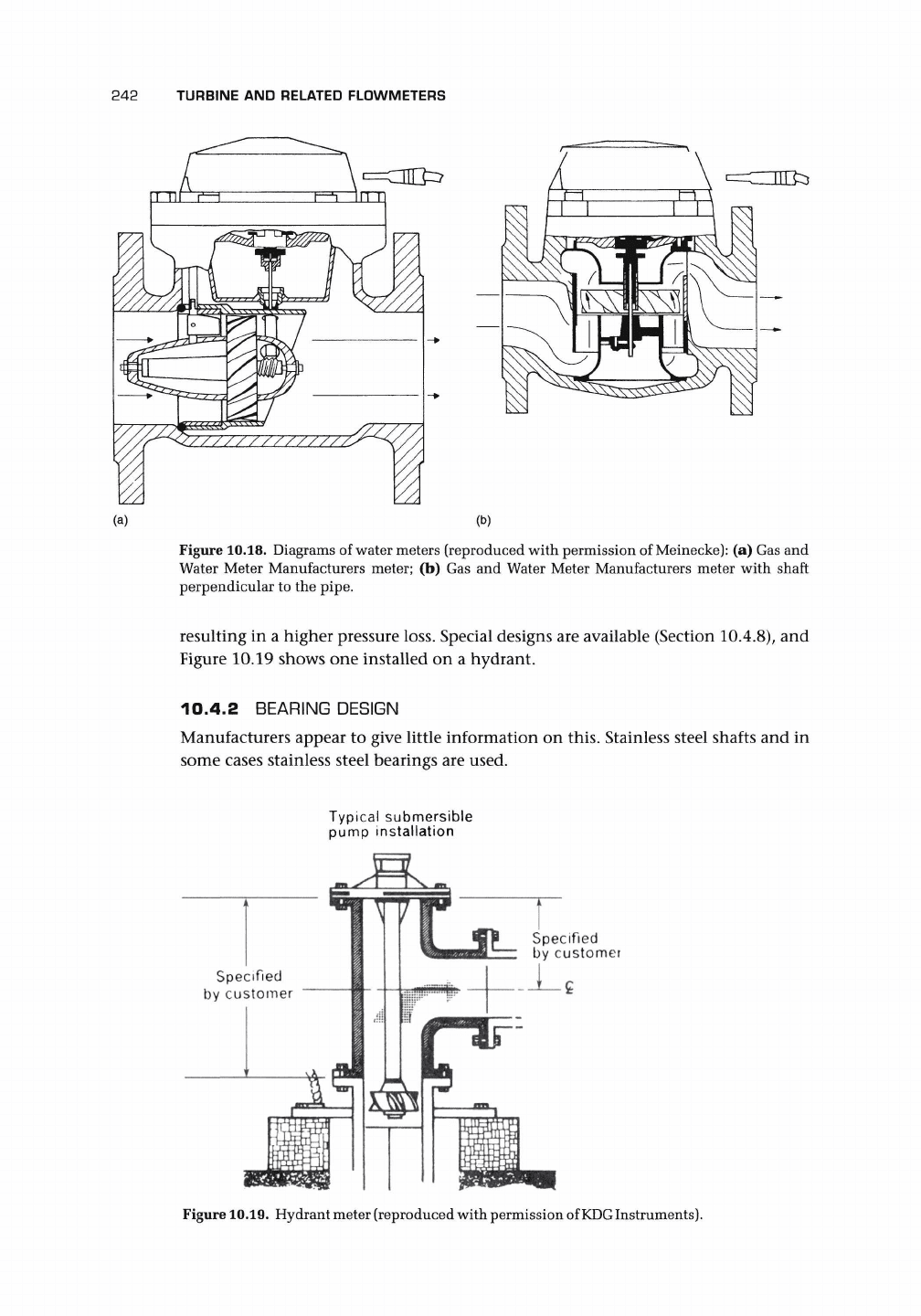
resulting in a higher pressure loss. Special designs are available (Section 10.4.8), and
Figure 10.19 shows one installed on a hydrant.
10.4.2 BEARING DESIGN
Manufacturers appear to give little information on this. Stainless steel shafts and in
some cases stainless steel bearings are used.
Typical submersible
pump installation
Specified
by customer
Figure
10.19.
Hydrant meter (reproduced with permission of
KDG
Instruments).
10.4 WATER METERS 243
10.4.3 MATERIALS
For temperatures up to 40° C, polythene propellers are suitable, but for meters for
hot water, the internals are of hot-water-resistant plastic up to 150°C, and for tem-
peratures up to 200° C, the measuring element may be red bronze and the wheel may
be stainless steel. Other materials used are brass and stainless steel.
10.4.4 SIZE RANGE
Meters range from 15 to 500 mm. One manufacturer has introduced a dual system,
which combines meters of very different capacity and uses a valve to control the
flow through the larger meter.
10.4.5 SENSING
This is usually via a gear train but may also use optoelectrical methods, reed switches,
etc.
10.4.6 CHARACTERISTICS
AND
ACCURACY
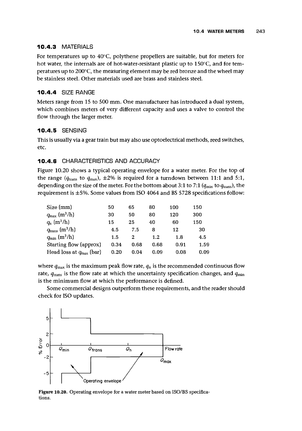
Figure 10.20 shows a typical operating envelope for a water meter. For the top of
the range (g
t
rans to
q
max
),
±2% is required for a turndown between 11:1 and 5:1,
depending on the size of the meter. For the bottom about 3:1 to 7:1 (g
min
to
quans),
the
requirement is ±5%. Some values from ISO 4064 and
BS
5728 specifications follow:
Size
(mm) 50 65 80 100 150
qmax
(m
3
/h) 30 50 80 120 300
q
n
(m
3
/h) 15 25 40 60 150
q
trans
(m
3
/h)
q
min
(m
3
/h)
Starting flow (approx)
Head loss at g
max
(bar)
4.5
1.5
0.34
0.20
7.5
2
0.68
0.04
8
1.2
0.68
0.09
12
1
0
0
.8
.91
.08
30
4.5
1.59
0.09
where q
max
is the maximum peak flow rate, q
n
is the recommended continuous flow
rate,
g
t
rans is the flow rate at which the uncertainty specification changes, and g
min
is the minimum flow at which the performance is defined.
Some commercial designs outperform these requirements, and the reader should
check for ISO updates.
5 -
2
o
£ 0
-2
-5 -
Figure 10.20. Operating envelope for a water meter based on ISO/BS specifica-
tions.
^min
<?trons
\
\
Operating
envelope
/
i
On
/
/
Flow rate
^max
244
TURBINE
AND
RELATED FLOWMETERS
10.4.7
INSTALLATION
A typical requirement
for
installation
is
5D
upstream.
In
addition,
air and
solid
matter should
be
avoided.
10.4.8
SPECIAL DESIGNS
Irrigation and mainline designs are inserted through openings
in
the pipe, manholes,
and saddles
or
by
a
bolted flange
in a
T
piece. Accuracy
is
unlikely
to
be
high. Sizes
can
be as
great
as 1,000 mm
in
diameter.
10.5 OTHER PROPELLER
AND
TURBINE METERS
10.5.1
QUANTUM DYNAMICS FLOWMETER
One design used
a
patented twin-turbine configuration whereby
the
downstream
slave turbine drove
the
shaft
on
which
the
indicator turbine bearings rotate freely.
Under normal conditions,
the
rotational speeds
of
the
indicator
and
slave turbines
are closely matched.
At
high flow rates,
the
rotational speeds
of the
indicator
tur-
bine
and the
slave turbine/shaft assembly will begin
to
diverge.
An
integral flow-
straightening device upstream
of
the
indicator turbine reduces swirl
and
hence
the
effect
of
upstream flow distortion. With
a
special design
of
RF
pickup, claims
of
±0.01%
linearity
for
a
turndown
of
between 350:1
and
500:1 have been made.
In
gaseous flow, these rangeabilities were claimed
to
correspond
to
a
mass turndown
in excess
of
1,000:1.
10.5.2
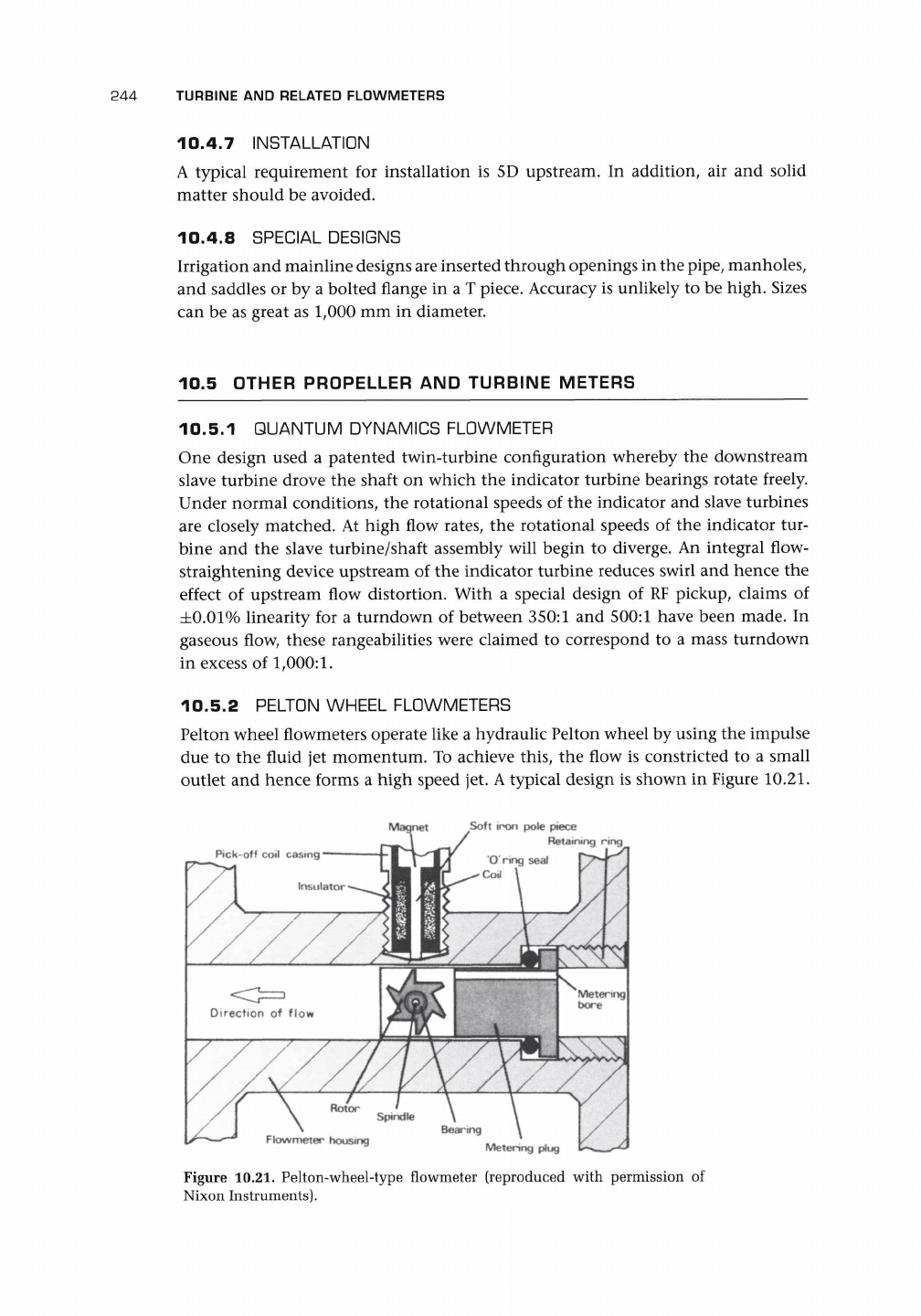
PELTON WHEEL FLOWMETERS
Pelton wheel flowmeters operate like
a
hydraulic Pelton wheel
by
using
the
impulse
due
to the
fluid
jet
momentum.
To
achieve this,
the
flow
is
constricted
to
a
small
outlet
and
hence forms
a
high speed
jet.
A typical design
is
shown
in
Figure
10.21.
Pick-off coil casing
Insulator
Soft iron pole piece
Retaining ring
O ring seal
Co*l
\ 1/
/
/
\
Bearing
/•
'—*
Flowmeter housing
__
Metering plug
fc-
Figure
10.21.
Pelton-wheel-type flowmeter (reproduced
wi
Nixon Instruments).
with permission
of
10.6 CHAPTER CONCLUSIONS 245
It
is
designed for use with liquids. An up-
stream filter with
a
60-mesh insert may be
recommended. A typical low flow range
is
0.18-1.81/min with a repeatability claimed
as ±0.25%. The passing of the rotor tips
is
sensed by a reluctance pickup.
Other designs on the Pelton wheel prin-
ciple have also been used to produce meters
capable
of
flow rates as low as 0.06 1/h
to
0.75 m
3
/h with repeatability
of
±0.3% of
FSD.
Alternatively, they have been used as
a bypass flowmeter, which operates across
an orifice to allow higher ranges.
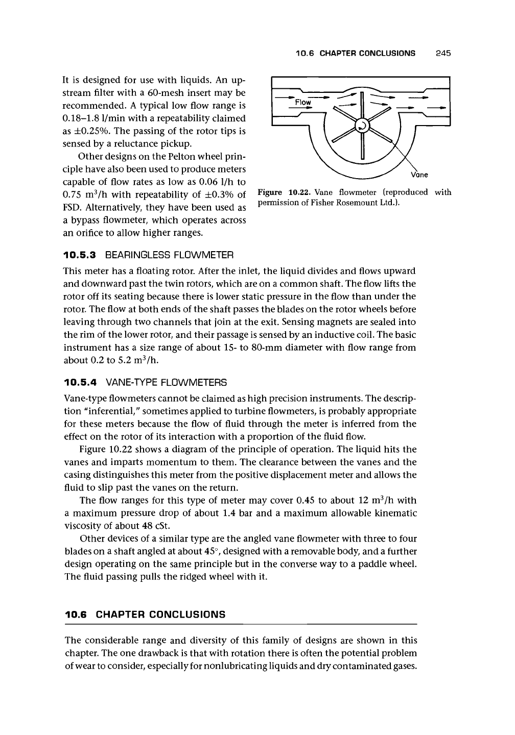
Vane
Figure 10.22. Vane flowmeter (reproduced with
permission of Fisher Rosemount Ltd.).
10.5.3
BEARINGLESS FLOWMETER
This meter has
a
floating rotor. After the inlet, the liquid divides and flows upward
and downward past the twin rotors, which are on a common shaft. The flow lifts the
rotor off its seating because there is lower static pressure in the flow than under the
rotor. The flow at both ends of the shaft passes the blades on the rotor wheels before
leaving through two channels that join at the exit. Sensing magnets are sealed into
the rim of the lower rotor, and their passage is sensed by an inductive coil. The basic
instrument has
a
size range of about 15- to 80-mm diameter with flow range from
about 0.2 to 5.2 m
3
/h.
10.5.4
VANE-TYPE FL0WMETERS
Vane-type flowmeters cannot be claimed as high precision instruments. The descrip-
tion "inferential," sometimes applied to turbine flowmeters, is probably appropriate
for these meters because the flow
of
fluid through the meter is inferred from the
effect on the rotor of its interaction with a proportion of the fluid flow.
Figure 10.22 shows
a
diagram of the principle of operation. The liquid hits the
vanes and imparts momentum to them. The clearance between the vanes and the
casing distinguishes this meter from the positive displacement meter and allows the
fluid to slip past the vanes on the return.
The flow ranges for this type
of
meter may cover 0.45
to
about 12 m
3
/h with
a maximum pressure drop
of
about 1.4 bar and
a
maximum allowable kinematic
viscosity of about 48 cSt.
Other devices of a similar type are the angled vane flowmeter with three to four
blades on a shaft angled at about 45°, designed with a removable body, and a further
design operating on the same principle but in the converse way to a paddle wheel.
The fluid passing pulls the ridged wheel with it.
10.6 CHAPTER CONCLUSIONS
The considerable range and diversity
of
this family
of
designs are shown
in
this
chapter. The one drawback is that with rotation there is often the potential problem
of wear to consider, especially for nonlubricating liquids and dry contaminated gases.
246 TURBINE AND RELATED FLOWMETERS
However, against this must be set their extraordinary
versatility.
Very high accuracy is
achieved in some; very large turndown ratio is achieved in others; and suitability for
a wide range of fluids and a very wide price range are also features of the family. New
designs with extraordinarily great turndown and others with self-checking ability
indicate that the family is far from dying out.
The problem of bearing wear has been controlled but requires that all types of
meter are subject to regular maintenance, van der Kam and de Jong (1994) claimed
that the gas turbine meter, calibrated at the operational pressure, can be one of the
most accurate gas meters available at present and could be used more for custody
transfer. Gasunie have suffered very few mechanical failures (blade failure or dam-
aged bearings) and van der Kam and Dam (1993) reckon the turbine meter still the
best option and capable of further development.
Great care must be exercised in ensuring that the installation does not invali-
date the calibration. Transient behavior in gases results in an overregistration of the
flow. New sensor technologies may lead to lower drag and higher integrity of signal,
particularly in adverse radiation environments.
Intelligent designs that build in a self-checking or condition-monitoring facility
are likely to be of particular value for metering high value fluids in fiscal and custody
transfer applications.
Theoretical analysis of flow through the meter should take account of the
very small deflection compared with the substantial deflection that occurs in a
power turbine. Ferreira (1988) attempted some computational work on the flows
within some turbine meters and compared these with LDA measurements. The
results were interesting and original, but the nature of the flow and the very
small deflections, which result in the case of a well-designed rotor, suggest that
future computations should take account of these features in a perturbation-type
analysis.
APPENDIX
1O.A
Turbine Flowmeter Theory
10.A.1 DERIVATION OF TURBINE FLOWMETER
TORQUE EQUATIONS
Blade Aerodynamics
There are two distinct approaches to the blade forces in the literature. Using cascade
theory, Tsukamoto and Hutton (1985) give the driving force as
rV
2
z
s(t<mp
2
-
which equates the torque to the change in angular momentum of the fluid passing
through the blade row. Replacing p
x
by p - i and p
2
by p -
8,
and noting that both