Baker R.C. Flow Measurement Handbook: Industrial Designs, Operating Principles, Performance, and Applications
Подождите немного. Документ загружается.

10.2 PRECISION LIQUID METERS 227
10.2.8 SENSOR DESIGN AND PERFORMANCE
A direct mechanical drive to register may be used in large meters. However most
commonly, to obtain rotor speed, blade passing is sensed by the change in the mag-
netic field around the sensor. The terms given to the various methods suffer from
some variation, and the following are suggested for consistency (Olsen 1974):
a.
Inductive:
Magnets are embedded in the hub or blades, and a pickup coil with a
soft iron pole piece senses their passage;
b.
Variable
reluctance:
A permanent magnet with pickup coil is positioned in the
body of the flowmeter near the propeller/rotor, which senses the variation of the
flux due to the passage of each blade or shroud ring stud of highly permeable
magnetic rotor material;
c.
Radiofrequency
(RF):
An oscillator applies a high frequency carrier signal to the
coil in the pickup assembly, and the passing of the rotor blades modulates the
carrier. At very high frequencies of signal transmission, the skin effect is such
that the electromagnetic field is essentially reflected by the passing blades with
negligible drag effect on the wheel.
d.
Photoelectric:
A light beam is interrupted by the passage of the blades. Optical
fiber methods, which are intrinsically safe, may also be used where the light
reflects off the blade tips. The problem with this method is that the windows
tend to become fouled, and so light transmission through the liquid is not to
be recommended in many applications. Place and Maurer (1986) proposed an
optical system that overcame this problem where the blade passage rocked a
magnetic element and the rocking was sensed optically;
e.
Magnetic reed
switch:
Contacts are opened and closed by magnets in the rotor or
some rotating part of the meter.
The resulting signal must be amplified with care and shielded from extraneous noise
due to voltage sources or magnetic fields because spurious pulses can introduce sig-
nificant errors.
Vibration may also cause microphonic effects. Screened cable should be used, and
the distance from the flowmeter to the preamplifier should be as short as possible
and typically not greater than 2 m.
Typically the pulse is amplified from about 15 mV root-mean-square (RMS) to 8
V
amplitude (increases with flow rate) and is of
0.5-
to 20-ms duration. The pulse rate
ranges from 50 Hz to 3 kHz, and impedance from 300 to 1,500 ohms. A maximum
transmission cable length has been given as 1,000 m by one manufacturer. The signal
is then applied to a signal converter, an electronic gearbox, to convert pulse rate into
cubic meters per hour and total into cubic meters.
A
high pulse density is desirable
where a meter is to be calibrated against a volumetric standard such as a prover loop
where generally it is recommended that 10,000 pulses or more should be collected
per unit reference volume. Eide (1991) described a 12-in. Brooks Compact Prover
and a 3-in. Brooks turbine meter modified to give 27,000 pulses/m
3
, which were
used to calibrate pipe provers. The uncertainty of the water draw was better than
±0.003%,
and the master meter's uncertainty was 0.02%.
Ball (1977) demonstrated that below about 1/3 FSD, the drag due to a magnetic
pickup could cause differences compared with an RF pickup and at 1/6 FSD could
indicate an error of 4% rising further with decreasing speed.
228 TURBINE AND RELATED FLOWMETERS
Typical
Performance
Curves
±0.12%
reading ovei
{restricted flow range
±0.25%
of
reading over
operating flow range
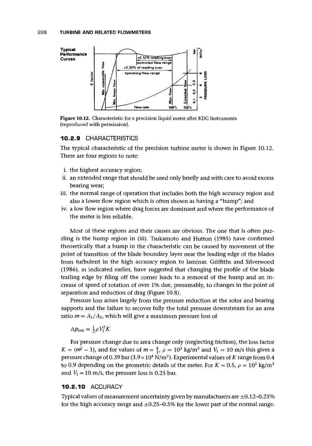
Figure 10.12. Characteristic for a precision liquid meter after KDG Instruments
(reproduced with permission).
10.2.9 CHARACTERISTICS
The typical characteristic
of
the precision turbine meter
is
shown
in
Figure 10.12.
There are four regions
to
note:
i. the highest accuracy region;
ii.
an extended range that should be used only briefly and with care to avoid excess
bearing wear;
iii.
the normal range
of
operation that includes both the high accuracy region and
also
a
lower flow region which is often shown as having
a
"hump"; and
iv. a low flow region where drag forces are dominant and where the performance of
the meter is less reliable.
Most
of
these regions
and
their causes are obvious. The one that
is
often puz-
zling
is the
hump region
in
(iii). Tsukamoto
and
Hutton (1985) have confirmed
theoretically that
a
hump
in the
characteristic can be caused
by
movement
of
the
point
of
transition
of
the blade boundary layer near the leading edge
of
the blades
from turbulent
in the
high accuracy region
to
laminar. Griffiths
and
Silverwood
(1986),
as
indicated earlier, have suggested that changing the profile
of
the blade
trailing edge
by
filing
off the
corner leads
to a
removal
of the
hump
and an in-
crease
of
speed
of
rotation
of
over 1% due, presumably,
to
changes
in
the point of
separation and reduction
of
drag (Figure 10.8).
Pressure loss arises largely from the pressure reduction
at
the rotor and bearing
supports and the failure
to
recover fully the total pressure downstream
for an
area
ratio m
=
A\/A
2l
which will give
a
maximum pressure loss of
For pressure change due to area change only (neglecting friction), the loss factor
K
=
(m
2
-
1), and
for
values
of
m =
|, p =
10
3
kg/m
3
and
V
x
=
10 m/s this gives
a
pressure change of 0.39 bar
(3.9 x
10
4
N/m
2
). Experimental values of
K
range from 0.4
to 0.9 depending on the geometric details
of
the meter. For K = 0.5,
p =
10
3
kg/m
3
and
V\
= 10 m/s, the pressure loss is 0.25 bar.
10.2.10 ACCURACY
Typical values of measurement uncertainty given by manufacturers are ±0.12-0.25%
for the high accuracy range and ±0.25-0.5% for the lower part of the normal range.
10.2 PRECISION LIQUID METERS 229
This is sometimes given as a linearity. The meters are capable of calibration to achieve
these values and possibly slightly better than ±0.1 to 0.5% over a turndown ratio
of 6:1 at least and up to 18:1 for thrust-compensated designs. With achievable un-
certainty of ±0.15%, they can meet the requirements of oil pipeline and custody
transfer applications.
Repeatability is typically given as ±0.05% for meters of less than or equal to
50 mm and ±0.02% for meters of greater than or equal to 75 mm. Such precision
values do not take into account bias errors often present in calibration equipment.
Mattingly et al. (1977) obtained day-to-day laboratory repeatability of ±0.07-0.12%.
Shafer (1962) made the important point that before calibration the meter needs
to be soaked in the calibration fluid and run for some time beforehand. He ob-
tained impressive performances of 0.1-0.2% agreement as typical of year-to-year
repeatability.
These meters are widely used as transfer standards, and for best performance
the meter is calibrated with upstream and downstream pipework and an upstream
straightener. Twin meter packages of turbine and other meter types have been used
for transfer standards, but Minkin et al. (1966) used a twin turbine meter arrange-
ment to give extra confidence.
Withers et al. (1971) tested 5 x 75 mm meters on water, kerosene, gas oil, and
spindle oil and obtained repeatability to better than ±0.05% (95% confidence)
on all. However the characteristics were very varied when used with different
liquids and temperatures. The temperature effect was shown to be due more to
viscosity than to expansion. Despite the apparent variation, the authors claimed
to be able to determine a universal curve for each meter in terms of Reynolds
number.
Minkin et al. (1966) reported extensive tests on two groups of meters rang-
ing from about 20 to 50 mm diameter in which they showed the following
results.
a. The calibration factor for full scale had a maximum deviation from the mean
over 2 years of 0.6%.
b.
The calibration factor for water and liquid hydrogen for a good meter (horizontal
and vertical orientation) varied by less than 1% over 3 years apart from one
occasion with 2% change.
c. The orientation of meters affected lower range values more than full
scale.
d. The effect of thermal expansion resulted in a calibration factor ratio for
C
wate
r/
Qiquidhydrogen of 0.991-0.994 theoretically with wider experimental variation
(cf. Shamp 1971 who reckoned registration for liquid nitrogen at -190°C was
1.5-1.9%
less than for water at about 15°C).
It is also necessary to calibrate in the same orientation as installation.
10.2.11 INSTALLATION
Installation is one of the major causes of meter error. The ideal long straight length
of upstream pipe required to achieve a fully developed (usually turbulent) profile
is seldom possible even in calibration facilities. It may be worth considering the
230 TURBINE AND RELATED FLOWMETERS
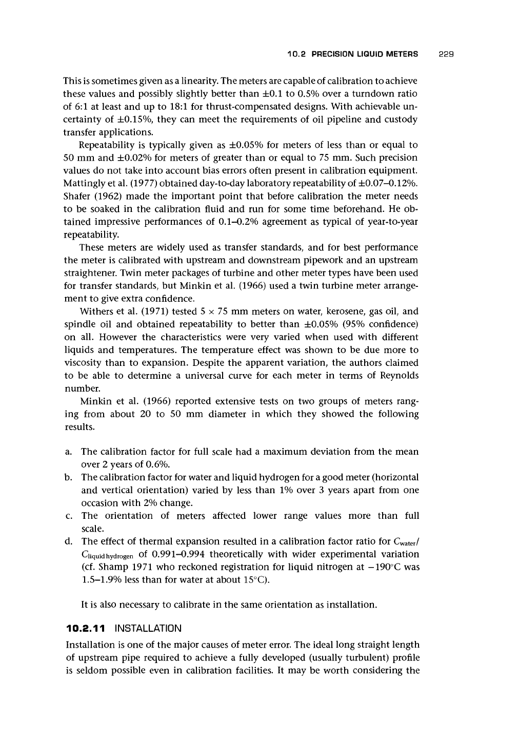
To achieve the maximum performance from a turbine flowmeter it is essential that straight pipe sections are
fitted immediately upstream and downstream of the flowmeter position. For liquid flows the dimensions
indicated below should be considered a minimum and for gas flow they should be multiplied by 4.
flow straightener
T
3D 5D minimum
10D minimum
5D minimum
Figure 10.13. Installation for
a
precision liquid meter as suggested by Quadrina
Ltd.
(reproduced
with permission).
calibration of the flowmeter together with surrounding pipework and straightener,
to eliminate, as far as possible, the effect of upstream flow effects. Because of the
susceptibility of turbine meters to asymmetry and swirl, generated by upstream fit-
tings,
it is common for manufacturers to provide recommendations for upstream
pipe configurations, including the use of flow conditioners. In most cases these
will, presumably, be to avoid additional error. These are sometimes accompanied by
a diagram. A typical example is shown in Figure
10.13.
This suggests that an up-
stream straight length of 10 diameters is required, with the downstream end of a
flow straightener, 3D long, positioned at least 5D upstream of the meter. It is always
slightly surprising that some other manufacturers, who provide a useful diagram like
this one, suggest that without a flow straightener the user should still allow only,
say, 10D of straight pipe upstream of the flowmeter.
ANSI/API have suggested from experience that an upstream length of 20D and
a downstream length of 5D provided effective straightening in many installations.
In addition, maximum allowable misalignment of the meter bore and the preceding
pipework has been given as
5%.
Values are given in Table 10.2 for upstream distances
for particular fittings for a commercial instrument, which have also been given by
API.
Wafer construction has been available, allowing installation between flanges.
Presumably great care is needed in the positioning of this meter to obtain sat-
isfactory results. Published data suggest that some of these figures for upstream
spacing may be overly optimistic and that
the uncertain effects of an upstream valve
indicate the need to avoid this configura-
tion and, if unavoidable, to use a straight-
ener.
Larger hub-to-tip ratios appear to be
less sensitive to profile, and the larger the
tip clearance the less the sensitivity. Salami
(1984) confirmed that a commercial meter
with a hub-to-tip ratio of about 0.5 and a tip
clearance of 10% was almost insensitive to
changes from uniform to turbulent profile
(cf. Tan 1976 and Jepson and Bean 1969).
Table 10.2. An example of upstream
spacings from manufacturer
Fitting
Reducer
Swept elbow
Two swept bends in
the same plane
Two swept bends in
perpendicular planes
Valve
Upstream Distance
15D
20D
25D
40D
50D
10.2 PRECISION LIQUID METERS
231
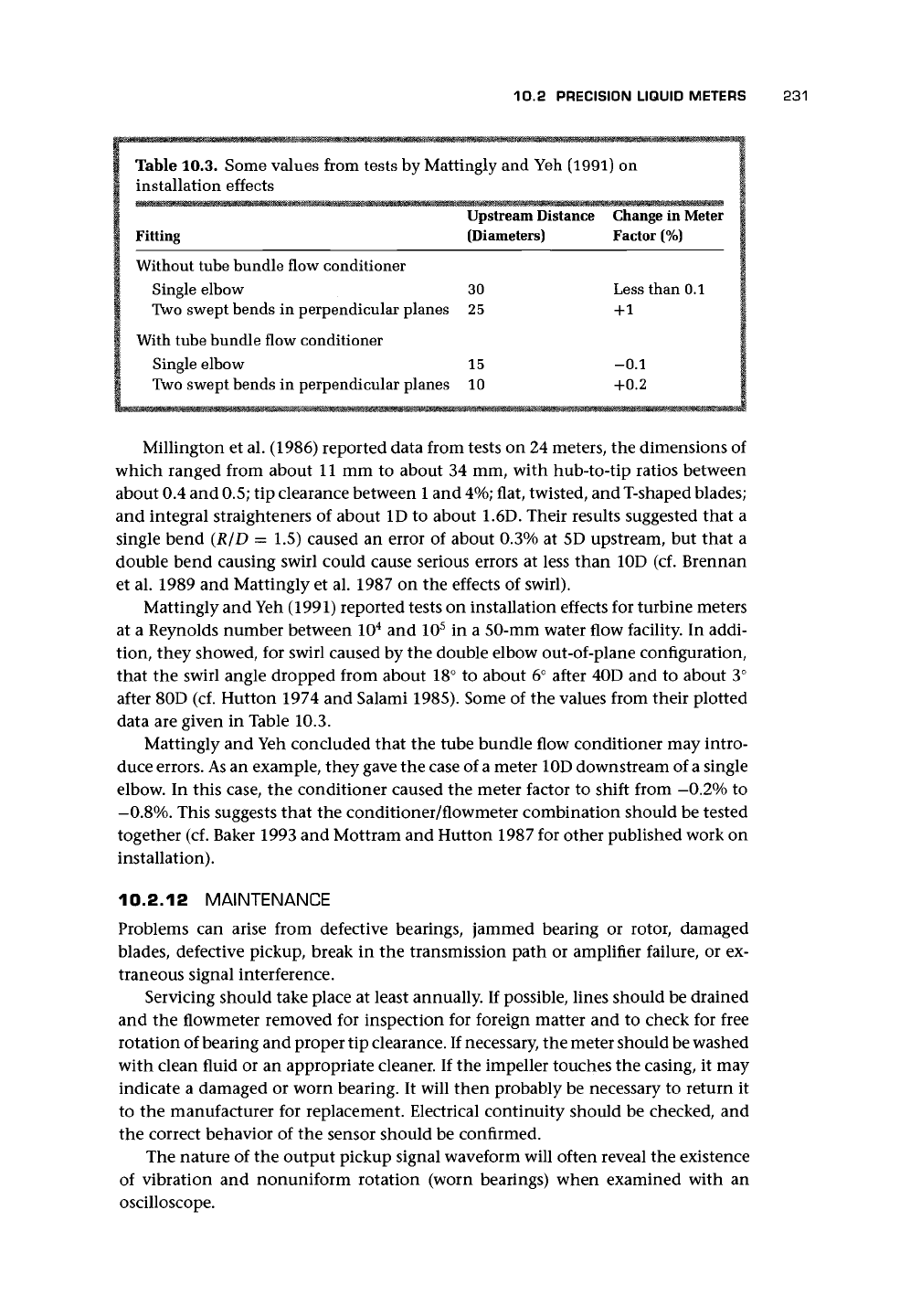
Table 10.3. Some values from tests by Mattingly and Yeh (1991) on
installation effects
Upstream Distance Change
in
Meter
Fitting (Diameters) Factor
(%)
Without tube bundle flow conditioner
Single elbow 30 Less than 0.1
Two swept bends in perpendicular planes 25 +1
With tube bundle flow conditioner
Single elbow 15 -0.1
Two swept bends in perpendicular planes 10 +0.2
Millington
et
al. (1986) reported data from tests
on 24
meters,
the
dimensions of
which ranged from about
11 mm to
about
34 mm,
with hub-to-tip ratios between
about 0.4 and
0.5;
tip clearance between
1
and
4%;
flat, twisted, and T-shaped blades;
and integral straighteners
of
about
ID to
about
1.6D.
Their results suggested that
a
single bend
(R/D = 1.5)
caused
an
error
of
about 0.3%
at 5D
upstream,
but
that
a
double bend causing swirl could cause serious errors
at
less than
10D (cf.
Brennan
et al. 1989
and
Mattingly
et
al. 1987
on the
effects
of
swirl).
Mattingly
and
Yeh (1991) reported tests
on
installation effects
for
turbine meters
at
a
Reynolds number between
10
4
and 10
5
in a
50-mm water flow facility.
In
addi-
tion, they showed,
for
swirl caused
by the
double elbow out-of-plane configuration,
that
the
swirl angle dropped from about
18° to
about
6°
after
40D and to
about
3°
after 80D
(cf.
Hutton 1974
and
Salami 1985). Some
of the
values from their plotted
data
are
given
in
Table 10.3.
Mattingly
and
Yeh concluded that
the
tube bundle flow conditioner
may
intro-
duce errors.
As
an
example, they gave the case
of
a
meter 10D downstream
of
a single
elbow.
In
this case,
the
conditioner caused
the
meter factor
to
shift from -0.2%
to
-0.8%.
This suggests that
the
conditioner/flowmeter combination should
be
tested
together
(cf.
Baker 1993
and
Mottram
and
Hutton 1987
for
other published work
on
installation).
10.2.12 MAINTENANCE
Problems
can
arise from defective bearings, jammed bearing
or
rotor, damaged
blades, defective pickup, break
in the
transmission path
or
amplifier failure,
or ex-
traneous signal interference.
Servicing should take place
at
least annually.
If
possible, lines should
be
drained
and
the
flowmeter removed
for
inspection
for
foreign matter
and to
check
for
free
rotation of bearing and proper tip clearance. If necessary, the meter should be washed
with clean fluid
or an
appropriate cleaner.
If
the impeller touches
the
casing,
it may
indicate
a
damaged
or
worn bearing.
It
will then probably
be
necessary
to
return
it
to
the
manufacturer
for
replacement. Electrical continuity should
be
checked,
and
the correct behavior
of the
sensor should
be
confirmed.
The nature
of the
output pickup signal waveform will often reveal
the
existence
of vibration
and
nonuniform rotation (worn bearings) when examined with
an
oscilloscope.
232 TURBINE AND RELATED FLOWMETERS
10.2.13
VISCOSITY,
TEMPERATURE,
AND
PRESSURE
Temperature differences between calibration and operation cause dimensional chan-
ges,
viscosity change, density change, and velocity pattern shifts (Gadshiev et al.
1988).
Manufacturers (cf. the standard documents) may provide correction factors
(cf. Hutton 1986 concerning a universal Reynolds number curve).
Linear range decreases progressively above
1
cSt and virtually disappears between
50 and 100 cSt. Helical blades are affected much less by viscosity change than con-
stant angle blades. Lower flow
rates,
smaller meter sizes, and high viscosity all lead to
decrease in the range of linear operation. Other causes are gum, varnish, and other
deposits on the bearings. A running-in period will usually overcome this problem.
Care is needed in specifying liquid type when purchasing a turbine meter for a par-
ticular application since the viscosity of, for instance, JP-5 fuel can vary from 0.8 to
10
cSt or more (cf. Ball 1977 who gave a polynomial series for the effect of viscosity).
Pressure and temperature will have an effect on the liquid volume and will also
affect the dimensions of the meter.
10.2.14 UNSTEADY FLOW
The effect of pulsation in liquid flow is much less than in gas flow because the
density of the rotor is closer to that of the fluid. There may, however, be a tendency
to overestimate the flow rate. Grey (1956) gave values of time constant for a range
of meter sizes and showed that, in the range 12-150 mm sensing element diameter,
the value was in the range 1-5 ms at full flow rate and 2-9 ms at half flow rate.
Increased blade angle was also noted to increase the time constant. Higson (1964)
suggested that the equation
^^ = exp(-t/fe) (10.7)
qq
where q
x
is the initial flow rate, q
2
is the final flow rate, q
t
is the flow rate at time
t, and £
R
is the relaxation time, gives the transient behavior of a meter. He showed
that, for the 20-mm meter used, change to 63% of the step change took about 0.6
revolutions and 6-110 ms. To return to equilibrium takes about 4t
R
.
One assumes, although to the author's knowledge there is no experimental flow
data, that when the wheel slows down as the flow in the pipeline stops, the liquid
or gas between the blades will be carried round in the wheel with little interchange
with the upstream or downstream fluid.
10.2.15 MULTIPHASE FLOW
Baker (1991a) contains a list of references relating to the use of the meter in mul-
tiphase flows. The turbine meter has been used in experiments to model nuclear
plant operating a long way from normal conditions (e.g., Ohlmer and Schulze 1985).
Under the resulting flows, high precision is not necessarily required. Much of the
published data for water-air flows do more to warn of the unpredictability than to
offer hope of high precision and some data appeared to exhibit a hysteresis effect
in vertical upward water-air flows. A small increase in air content from about 4%
to about 5% caused an error increase of about 15%, and this was not immediately
removed by reducing the air content back to 4%.
A
possible explanation was that a
10.2 PRECISION LIQUID METERS 233
vortex structure within the meter had trapped air and caused it to be drawn into the
bearing. Upstream jet mixing may reduce errors. Meter speed has also been found
to increase with increased solids concentration for the same volumetric flow rate. I
consider that the safe rule is to avoid using the meter in multiphase flows.
Mark et al. (1990a, 1990b) sought to interpret the data from the pulse spacing
in a turbine meter for void fraction measurement in a two-phase flow. They claimed
that fluctuation in the time between pulses was caused by the presence of the second
phase. They termed this variation signal turbulence and claimed that, at any flow
rate,
it was directly proportional to void fraction.
Johnson and Farroll (1995) claim that, even though errors in turbine water and
air flows can be as high as 12.5% for a void fraction of
25%,
the use of measurement
of the fluctuations in the turbine rotor speed can be used to measure void fraction
and water flow rate to an improved precision. The reader is referred to the original
article for more details but should be cautious when making general deductions from
this approach.
10.2.16 SIGNAL PROCESSING
Electrical noise may be the most troublesome element in turbine meter systems. Two
sensors are used where increased reliability and self-checking is required. However,
the signal-to-noise ratio should be high so that the counter is not affected by the
noise.
Footprinting of turbine meters can be used as a means of real-time measurement
monitoring and control. This has been used as a means to extend calibration inter-
vals (Gwaspari 1990). The use of the full-frequency spectrum, for so long discarded
as noise, opens up the possibility of condition monitoring particularly where the
theoretical understanding is sufficient to link the spectrum distribution with me-
chanical and electrical causes (Higham et al. 1986, Turner et al. 1989; however, cf.
Cheesewright et al. 1998).
10.2.17
APPLICATIONS
Typical applications are
in the process industries - providing precision, corrosion resistance, intrinsic
safety, good temperature and pressure rating, and ease of installation;
in oil (including crude) pipelines - where shroud rings may be used with nickel
rivets to increase the count rate by
4:1;
when duty payable on hydrocarbons;
may be able to cope with abrasive sand-laden crudes (Morse 1976);
in a range of mechanical engineering test rigs;
in the drinks and dairy industry;
in cryogenics - with ball and journal bearings in liquid hydrogen, oxygen, nitro-
gen, argon, carbon dioxide, normal and superfluid helium; rapid changes in
density which occur due to temperature changes; cryogenic fluids since they
are clean and of low viscosity. (The most appropriate bearing is one with stain-
less steel balls, nonmetallic cage, and preferably self-lubricating properties. Ro-
tors for cryogenic service are usually of a nickel alloy to ensure compatibility
with liquid oxygen);
234 TURBINE AND RELATED FLOWMETERS
in sanitary products - where the exacting requirements for precision measure-
ment are appropriate for turbine application;
as a secondary standard - to provide a transfer standard for the calibration of
other meters;
as a reference system - consisting of two meters in series so that the reference
system is self-checking. (Of course the meters need to be isolated from each
other by flow conditioning in the line between them);
for high pressure - with very high pressure capabilities; and
for high and low temperatures.
(cf. Baker 1993 for application references).
10.2.18 ADVANTAGES AND DISADVANTAGES
The compactness of the turbine meter gives it a considerable advantage over the
positive displacement meter. The pressure drop may be twice as great for a pos-
itive displacement meter. Short-term repeatability is excellent, being better than
0.02%, whereas long-term repeatability may be only 0.2% over a period of
6
months,
so that, for custody transfer, regular proving under operating conditions is neces-
sary. Although viscosity effects for large meters used with crude oil are less than for
smaller meters; nevertheless, a 200-mm meter will be affected by as much as
\°/o
for
changes from 1 to 30 cSt and will need to be reproved for large changes due to fluid
change or temperature. Above about 50 cSt, it will probably be necessary to use pos-
itive displacement meters. It is best for light products with viscosities which change
little.
Other advantages are pulsed output, reliability over extended periods, and rapid
response. Disadvantages are particles affecting bearing and wheel and sensitivity to
installation and swirl, which may affect calibration.
10.3 PRECISION GAS METERS
10.3.1 PRINCIPAL DESIGN COMPONENTS
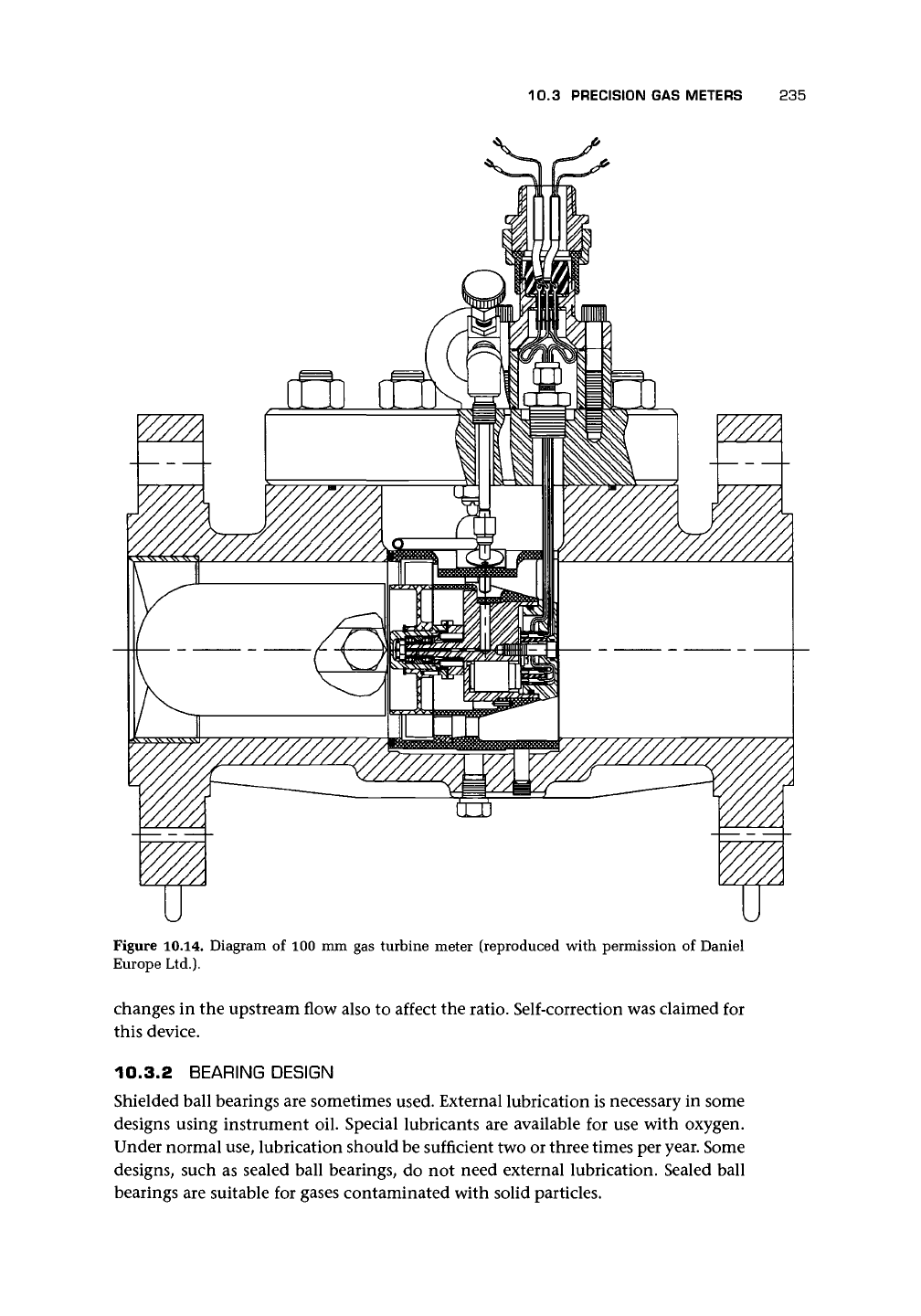
Figure 10.14 shows a typical gas turbine meter. Even though many of the previous
comments concerning liquid meters are relevant, it is clear that there are significant
design differences. The most obvious is the large hub and comparatively small flow
passage. The reason for this is to impart as large a torque as possible on the rotor by
moving the flow to the maximum radius and increasing the flow velocity. The sec-
ond difference is the frequent use of
a
worm and gear output drive, resulting from the
requirement by some national authorities for a mechanical display. It is common,
however, to include an electrical output as well as the mechanical register. Bonner
and Lee (1992) recorded some of the important innovations introduced into the de-
sign in the early 1960s; these innovations included flat helically twisted blades with
overlap and blade tips that extend into a recess in the outer wall of the flow passage.
Lee et al. (1982) described a design in which the main rotor was followed by
a second rotor to sense the condition of the installed flowmeter. The speed of the
second wheel as a ratio of the first would change if the flow leaving the first wheel
was deflected more by rotational constraints on the first wheel. It was possible for
10.3 PRECISION GAS METERS 235
Figure 10.14. Diagram of 100 mm gas turbine meter (reproduced with permission of Daniel
Europe Ltd.).
changes in the upstream flow also to affect the ratio. Self-correction was claimed for
this device.
10.3.2 BEARING DESIGN
Shielded ball bearings are sometimes used. External lubrication is necessary in some
designs using instrument oil. Special lubricants are available for use with oxygen.
Under normal use, lubrication should be sufficient two or three times per year. Some
designs, such as sealed ball bearings, do not need external lubrication. Sealed ball
bearings are suitable for gases contaminated with solid particles.
236 TURBINE AND RELATED FLOWMETERS
10.3.3 MATERIALS
Rotor material is typically Delrin or aluminum, usually the latter for sizes greater
than 150 mm. Sometimes stainless steel is used.
10.3.4 SIZE RANGE
For a 25-mm diameter, the range is from about 0.8-10 m
3
/h; for a 50-mm diameter,
the range is from about 5-100 m
3
/h (with a minimum flow response of 1.2 m
3
/h);
and for a 600-mm diameter, the range is from about
1,000-25,000
m
3
/h. One type
offers a
30:1
turndown ratio. Numbers of blades are typically 12 to 24, and maximum
pulse frequencies can be 3 kHz. The maximum pressure rating is up to 100 bar. These
figures can vary significantly between manufacturers.
The pressure loss in the meter at maximum flow rate is about 5.5 mbar for the
50-mm-diameter meter and 14 mbar for the 600-mm-diameter meter. Pressure loss
is,
of course, directly related to the density, and therefore to the pressure, of the
flowing gas. Reference should be made to manufacturers' data for given conditions.
10.3.5 ACCURACY
A typical specification for uncertainty is ±2% from the minimum flow rate Qmin
to 20% of the maximum flow rate Qmax, and ±1% from 20% Qmax to Qmax- Some
linearity claims of ±0.5% are made.
The linear performance may be as good as ±0.5% on about 20:1 turndown with
repeatability of ±0.02%. Maximum flow velocities can be up to 30 m/s. Other data
available to me show remarkable calibration stability with shifts of order ±0.2% in 9
years with about 10
8
m
3
of natural gas having been transported through the turbine
meters at
8-bar
line pressure.
van der Grinten (1990) gave an error curve for gas turbine meters, which allowed
for drag of gas between blades, annulus boundary layer, and friction in the bearing.
Figure 10.15 demonstrates this curve fit and also shows the behavior of the meter
with changing pressure and gas.
The turndown of the simple turbine meter increases proportionally with the
square root of the gas density ratio. At a pressure of 20 bar, the turndown can be as
high as 100:1 compared to 15:1 at a few millibars gauge working pressure (Griffiths
and Newcombe 1970). Watson and Furness (1977) claimed that for low pressure
nitrogen a flow range of 5:1 would be achieved, whereas for high pressure natural
gas the range might be as much as 30:1.
van der Kam and Dam (1993) found that turbines can operate within an envelope
of ±0.5% down to about 25% maximum flow, and of
±1%
in the lower range. They
also found that a pressure range of 1-10 bar caused errors well within 0.5% compared
with 1% in older turbines. The Reynolds number dependence of turbines may, in
some cases, allow the change in density to be related to curves of Reynolds number
dependence (cf. Lee and Evans 1965). Their data demonstrate a repeatability within
0.1%.
Another report (Erdal and Cabrol 1991) on calibration of
6
in.
x 6 in. turbine
meters suggested repeatability of about 0.24%, linearity of about 0.42%, and day-to-
day repeatability of about 0.05% or less; for periods in excess of 4 years, de Jong and
van der Kam (1993) suggested shifts in calibration of +0.2-0.3%, and Koning et al.
(1989) claimed shifts of order 0.1% in 10 years. Gasunie's experience suggests that