Baker R.C. Flow Measurement Handbook: Industrial Designs, Operating Principles, Performance, and Applications
Подождите немного. Документ загружается.

11.3 INDUSTRIAL DEVELOPMENTS OF VORTEX-SHEDDING FLOWMETERS 257
for a 3-in. (75-mm) meter in air over a 360:1 turndown (with a lower Reynolds
number of 10
4
) and showed that scatter was of order ±1% over the range. A major
problem in achieving this size of turndown is how to sense at the varying level
of signal. If velocity changes by
100:1,
then pressure head variation due to the
velocity will change by 10
4
:1.
Goujon-Durand (1995) confirmed that a minimum
Reynolds number of Re = 30,000 is probably necessary to avoid serious increase in
nonlinearity. Takahashi and Itoh (1993) showed a slight decrease in Strouhal number
(about 2%) from Re = 20,000 to Re = 50,000 for heavy oil, water, and air.
Inkley et al. (1980) obtained data to show the small effect of temperature change
through viscosity and density on the meter. Change of liquid and liquid viscosity
appears to have caused calibration shifts of order
0.5%.
If the meter is designed close
to the minimum in Figure 11.4(a), any variation due to temperature expansion will
be minimized. The major change was due to cavitation. The authors agreed with
White et al. (1974) that a universal curve should be obtainable and foreshadowed
the work of Takamoto and Terao (1994) and, no doubt, others.
11.3.2 BLUFF BODY SHAPE
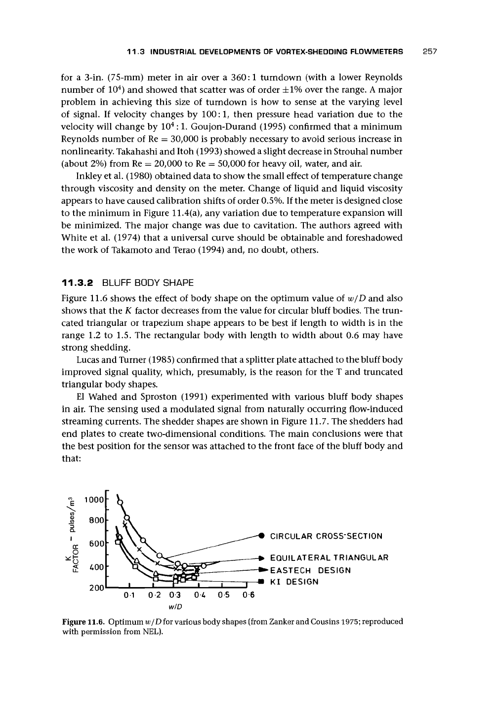
Figure 11.6 shows the effect of body shape on the optimum value of w/D and also
shows that the K factor decreases from the value for circular bluff bodies. The trun-
cated triangular or trapezium shape appears to be best if length to width is in the
range 1.2 to 1.5. The rectangular body with length to width about 0.6 may have
strong shedding.
Lucas and Turner (1985) confirmed that a splitter plate attached to the bluff body
improved signal quality, which, presumably, is the reason for the T and truncated
triangular body shapes.
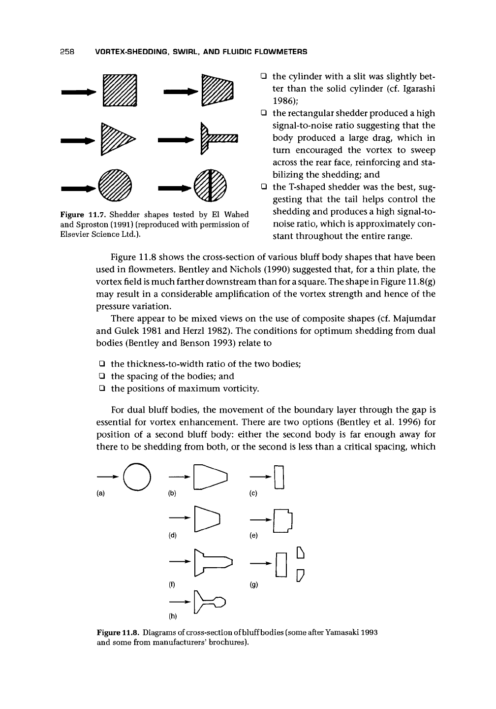
El Wahed and Sproston (1991) experimented with various bluff body shapes
in air. The sensing used a modulated signal from naturally occurring flow-induced
streaming currents. The shedder shapes are shown in Figure 11.7. The shedders had
end plates to create two-dimensional conditions. The main conclusions were that
the best position for the sensor was attached to the front face of the bluff body and
that:
1000
800
600
£00
200
CIRCULAR CROSS-SECTION
EQUILATERAL TRIANGULAR
•EASTECH DESIGN
KI DESIGN
0-1 02 03 0A 0-5 06
w/D
Figure 11.6. Optimum w/D for various body shapes (from Zanker and Cousins
1975;
reproduced
with permission from NEL).
258
VORTEX-SHEDDING, SWIRL, AND FLUIDIC FLOWMETERS
Figure 11.7. Shedder shapes tested by El Wahed
and Sproston (1991) (reproduced with permission of
Elsevier Science Ltd.).
• the cylinder with a slit was slightly bet-
ter than the solid cylinder (cf. Igarashi
1986);
• the rectangular shedder produced a high
signal-to-noise ratio suggesting that the
body produced a large drag, which in
turn encouraged the vortex to sweep
across the rear face, reinforcing and sta-
bilizing the shedding; and
• the T-shaped shedder was the best, sug-
gesting that the tail helps control the
shedding and produces a high signal-to-
noise ratio, which is approximately con-
stant throughout the entire range.
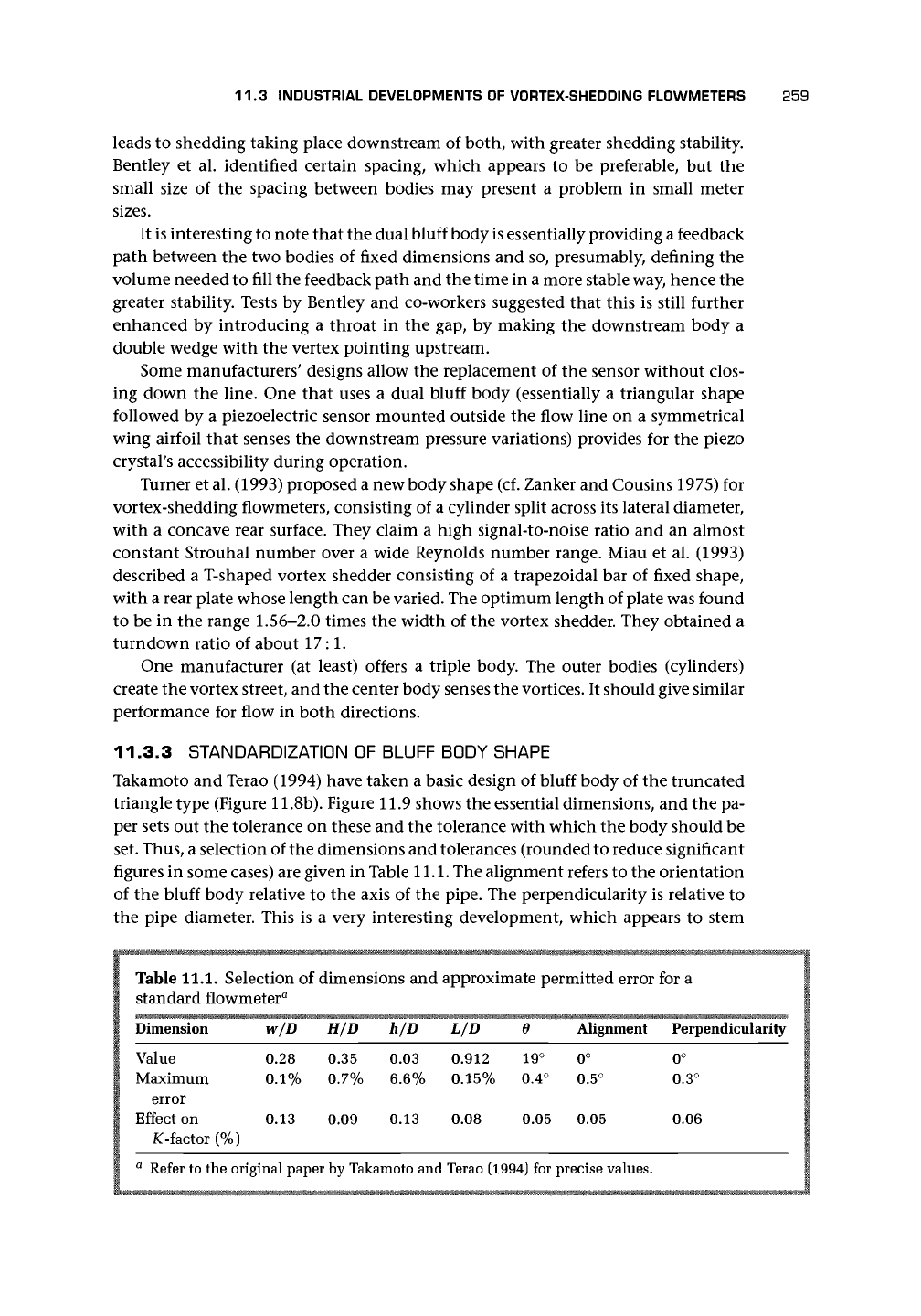
Figure 11.8 shows the cross-section of various bluff body shapes that have been
used in flowmeters. Bentley and Nichols (1990) suggested that, for a thin plate, the
vortex field is much farther downstream than for
a
square.
The shape in Figure 11.8(g)
may result in a considerable amplification of the vortex strength and hence of the
pressure variation.
There appear to be mixed views on the use of composite shapes (cf. Majumdar
and Gulek 1981 and Herzl 1982). The conditions for optimum shedding from dual
bodies (Bentley and Benson 1993) relate to
• the thickness-to-width ratio of the two bodies;
• the spacing of the bodies; and
• the positions of maximum vorticity.
For dual bluff bodies, the movement of the boundary layer through the gap is
essential for vortex enhancement. There are two options (Bentley et al. 1996) for
position of a second bluff body: either the second body is far enough away for
there to be shedding from both, or the second is less than a critical spacing, which
(a)
(d)
(f) (g)
V
(h)
Figure
11.8.
Diagrams of cross-section of bluff bodies (some after Yamasaki 1993
and some from manufacturers' brochures).
11.3 INDUSTRIAL DEVELOPMENTS OF VORTEX-SHEDDING FLOWMETERS 259
leads to shedding taking place downstream of both, with greater shedding stability.
Bentley et al. identified certain spacing, which appears to be preferable, but the
small size of the spacing between bodies may present a problem in small meter
sizes.
It is interesting to note that the dual bluff body
is
essentially providing a feedback
path between the two bodies of fixed dimensions and so, presumably, defining the
volume needed to fill the feedback path and the time in a more stable way, hence the
greater stability. Tests by Bentley and co-workers suggested that this is still further
enhanced by introducing a throat in the gap, by making the downstream body a
double wedge with the vertex pointing upstream.
Some manufacturers' designs allow the replacement of the sensor without clos-
ing down the line. One that uses a dual bluff body (essentially a triangular shape
followed by a piezoelectric sensor mounted outside the flow line on a symmetrical
wing airfoil that senses the downstream pressure variations) provides for the piezo
crystal's accessibility during operation.
Turner et al. (1993) proposed a new body shape (cf. Zanker and Cousins 1975) for
vortex-shedding flowmeters, consisting of a cylinder split across its lateral diameter,
with a concave rear surface. They claim a high signal-to-noise ratio and an almost
constant Strouhal number over a wide Reynolds number range. Miau et al. (1993)
described a T-shaped vortex shedder consisting of a trapezoidal bar of fixed shape,
with a rear plate whose length can be varied. The optimum length of plate was found
to be in the range
1.56-2.0
times the width of the vortex shedder. They obtained a
turndown ratio of about 17:1.
One manufacturer (at least) offers a triple body. The outer bodies (cylinders)
create the vortex street, and the center body senses the
vortices.
It should give similar
performance for flow in both directions.
11.3.3 STANDARDIZATION OF BLUFF BODY SHAPE
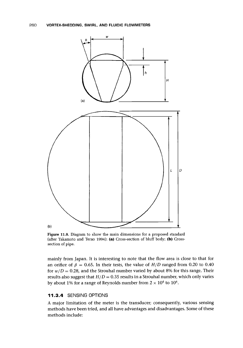
Takamoto and Terao (1994) have taken a basic design of bluff body of the truncated
triangle type (Figure 11.8b). Figure 11.9 shows the essential dimensions, and the pa-
per sets out the tolerance on these and the tolerance with which the body should be
set. Thus, a selection of the dimensions and tolerances (rounded to reduce significant
figures in some cases) are given in Table
11.1.
The alignment refers to the orientation
of the bluff body relative to the axis of the pipe. The perpendicularity is relative to
the pipe diameter. This is a very interesting development, which appears to stem
Table 11.1. Selection of dimensions and approximate permitted error for a
standard flowmeter
a
Dimension
Value
Maximum
error
Effect on
^-factor (%)
w/D
0.28
0.1%
0.13
H/D
0.35
0.7%
0.09
h/D
0.03
6.6%
0.13
L/D
0.912
0.15%
0.08
e
19°
0.4°
0.05
Alignment
0°
0.5°
0.05
Perpendicularity
0°
0.3°
0.06
a
Refer to the original paper by Takamoto and Terao (1994) for precise values.
260 VORTEX-SHEDDING, SWIRL, AND FLUIDIC FLOWMETERS
(b)
Figure 11.9. Diagram to show the main dimensions for a proposed standard
(after Takamoto and Terao 1994): (a) Cross-section of bluff body; (b) Cross-
section of pipe.
mainly from Japan. It is interesting to note that the flow area is close to that for
an orifice of p = 0.65. In their tests, the value of H/D ranged from 0.20 to 0.40
for w/D = 0.28, and the Strouhal number varied by about 8% for this range. Their
results also suggest that H/D = 0.35 results in a Strouhal number, which only varies
by about 1% for a range of Reynolds number from 2 x 10
4
to 10
6
.
11.3.4 SENSING OPTIONS
A major limitation of the meter is the transducer; consequently, various sensing
methods have been tried, and all have advantages and disadvantages. Some of these
methods include:
11.3 INDUSTRIAL DEVELOPMENTS OF VORTEX-SHEDDING FLOWMETERS 261
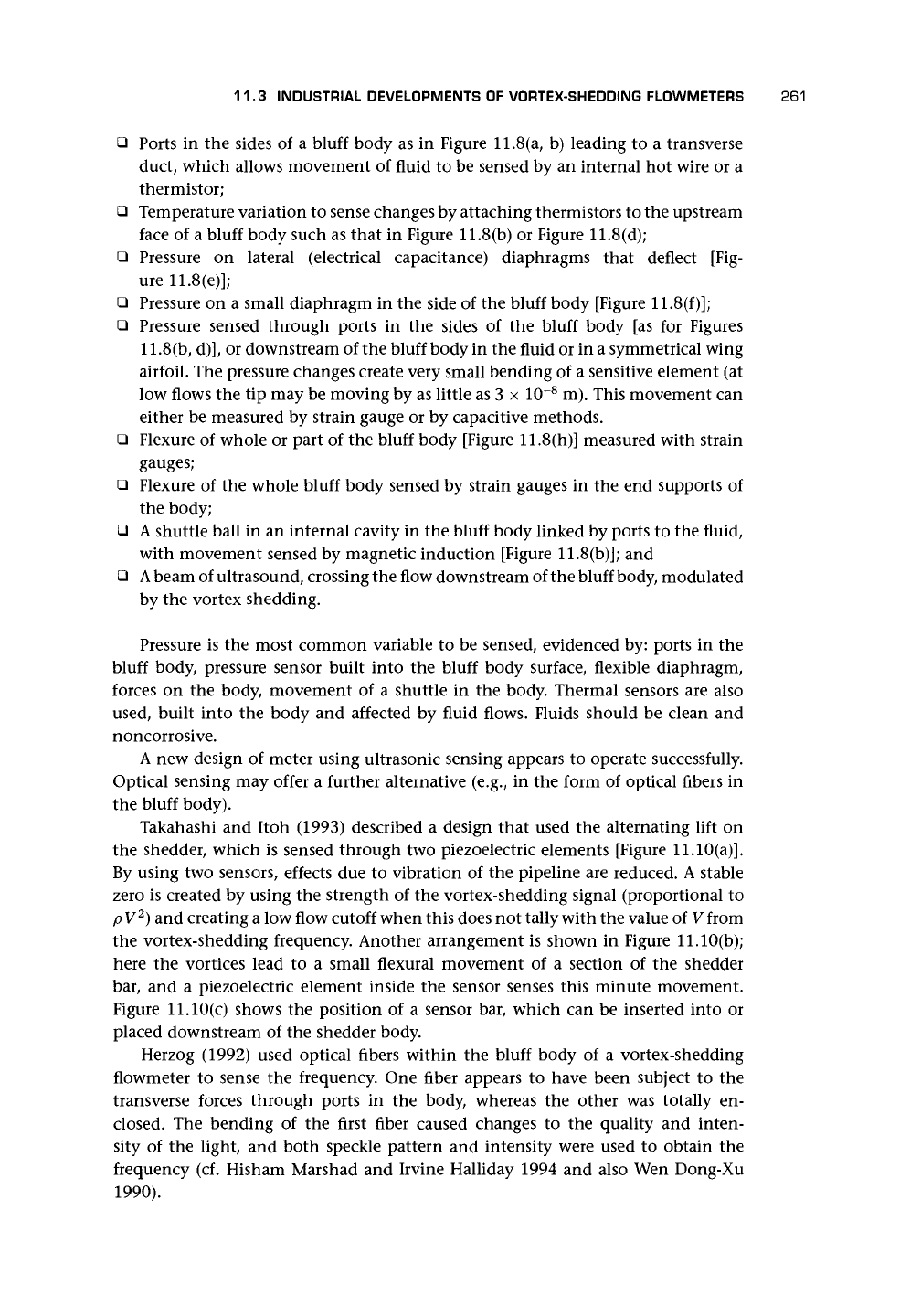
• Ports in the sides of a bluff body as in Figure 11.8 (a, b) leading to a transverse
duct, which allows movement of fluid to be sensed by an internal hot wire or a
thermistor;
• Temperature variation to sense changes by attaching thermistors to the upstream
face of a bluff body such as that in Figure 11.8(b) or Figure 11.8(d);
• Pressure on lateral (electrical capacitance) diaphragms that deflect [Fig-
ure 11.8(e)];
• Pressure on a small diaphragm in the side of the bluff body [Figure 11.8(f)];
• Pressure sensed through ports in the sides of the bluff body [as for Figures
11,8(b,
d)], or downstream of the bluff body in the fluid or in a symmetrical wing
airfoil. The pressure changes create very small bending of a sensitive element (at
low flows the tip may be moving by as little as 3 x 10~
8
m). This movement can
either be measured by strain gauge or by capacitive methods.
• Flexure of whole or part of the bluff body [Figure 11.8(h)] measured with strain
gauges;
• Flexure of the whole bluff body sensed by strain gauges in the end supports of
the body;
• A shuttle ball in an internal cavity in the bluff body linked by ports to the fluid,
with movement sensed by magnetic induction [Figure 11.8(b)]; and
•
A
beam of ultrasound, crossing the flow downstream of the bluff body, modulated
by the vortex shedding.
Pressure is the most common variable to be sensed, evidenced by: ports in the
bluff body, pressure sensor built into the bluff body surface, flexible diaphragm,
forces on the body, movement of a shuttle in the body. Thermal sensors are also
used, built into the body and affected by fluid flows. Fluids should be clean and
noncorrosive.
A new design of meter using ultrasonic sensing appears to operate successfully.
Optical sensing may offer a further alternative (e.g., in the form of optical fibers in
the bluff body).
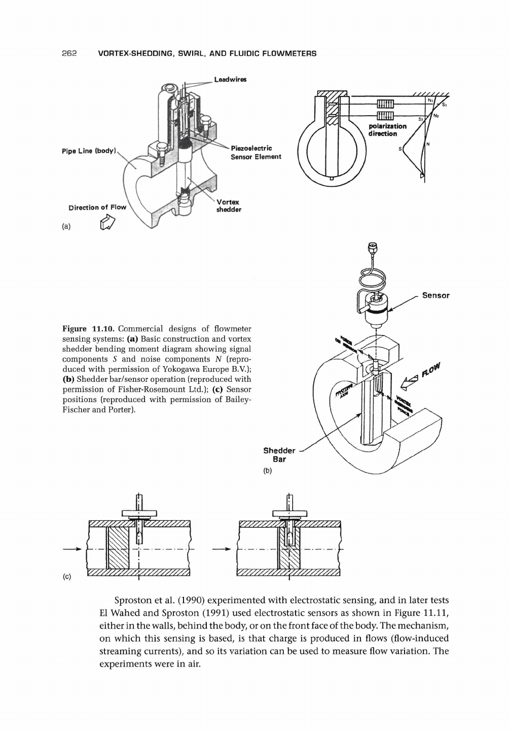
Takahashi and Itoh (1993) described a design that used the alternating lift on
the shedder, which is sensed through two piezoelectric elements [Figure 11.10(a)].
By using two sensors, effects due to vibration of the pipeline are reduced. A stable
zero is created by using the strength of the vortex-shedding signal (proportional to
p
V
2
) and creating a low flow cutoff when this does not tally with the value of V from
the vortex-shedding frequency. Another arrangement is shown in Figure 11.10(b);
here the vortices lead to a small flexural movement of a section of the shedder
bar, and a piezoelectric element inside the sensor senses this minute movement.
Figure 11.10(c) shows the position of a sensor bar, which can be inserted into or
placed downstream of the shedder body.
Herzog (1992) used optical fibers within the bluff body of a vortex-shedding
flowmeter to sense the frequency. One fiber appears to have been subject to the
transverse forces through ports in the body, whereas the other was totally en-
closed. The bending of the first fiber caused changes to the quality and inten-
sity of the light, and both speckle pattern and intensity were used to obtain the
frequency (cf. Hisham Marshad and Irvine Halliday 1994 and also Wen Dong-Xu
1990).
262 VORTEX-SHEDDING, SWIRL, AND FLUIDIC FLOWMETERS
Leadwires
Pipe Line (body)
Direction of Flow
(a)
Piezoelectric
Sensor Element
Figure 11.10. Commercial designs of flowmeter
sensing systems: (a) Basic construction and vortex
shedder bending moment diagram showing signal
components 5 and noise components N (repro-
duced with permission of Yokogawa Europe B.V.);
(b) Shedder bar/sensor operation (reproduced with
permission of Fisher-Rosemount Ltd.); (c) Sensor
positions (reproduced with permission of Bailey-
Fischer and Porter).
Sensor
(c)
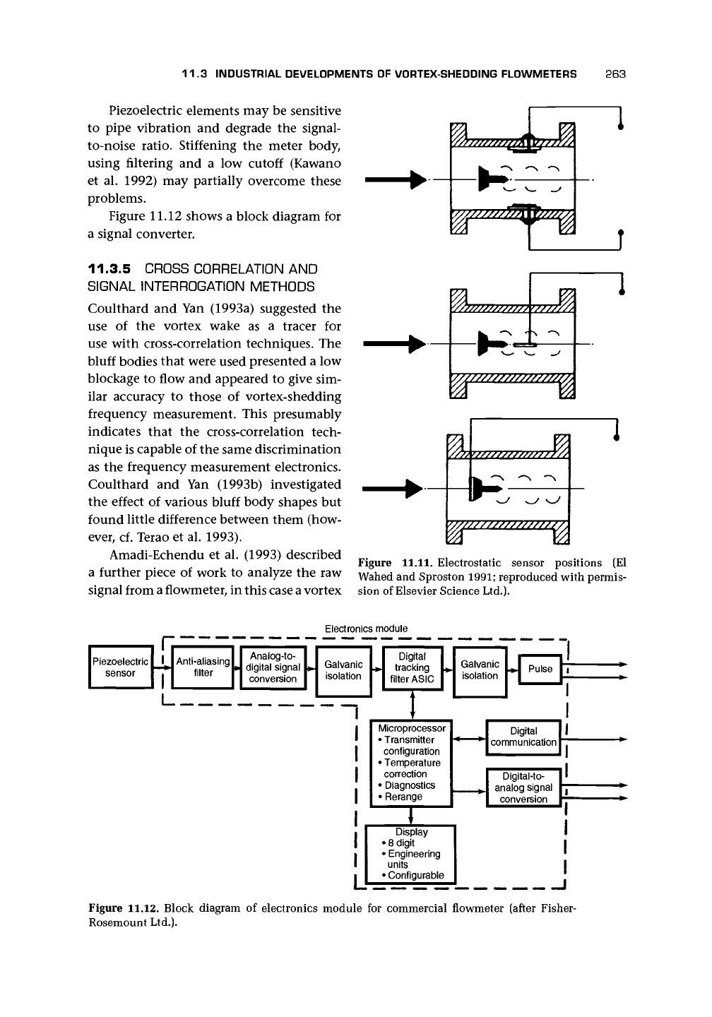
Sproston et al. (1990) experimented with electrostatic sensing, and in later tests
El Wahed and Sproston (1991) used electrostatic sensors as shown in Figure
11.11,
either in the
walls,
behind the body, or on the front face of the
body.
The mechanism,
on which this sensing is based, is that charge is produced in flows (flow-induced
streaming currents), and so its variation can be used to measure flow variation. The
experiments were in air.
11.3 INDUSTRIAL DEVELOPMENTS OF VORTEX-SHEDDING FLOWMETERS
263
Piezoelectric elements may be sensitive
to pipe vibration and degrade the signal-
to-noise ratio. Stiffening the meter body,
using filtering and
a
low cutoff (Kawano
et al. 1992) may partially overcome these
problems.
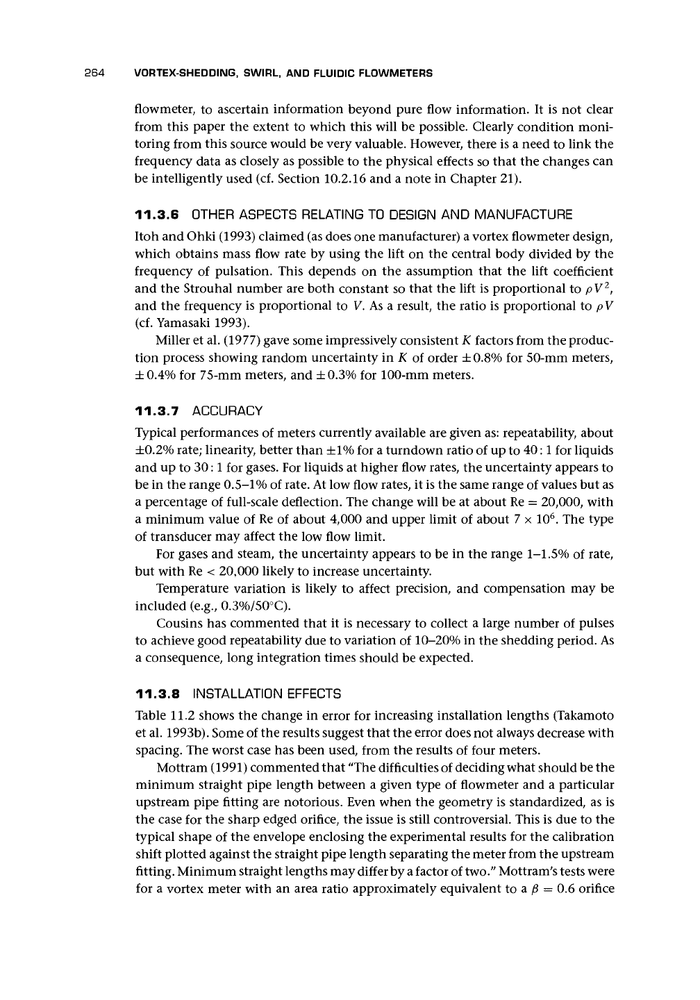
Figure 11.12 shows a block diagram for
a signal converter.
11.3.5 CROSS CORRELATION AND
SIGNAL INTERROGATION METHODS
Coulthard and Yan (1993a) suggested the
use
of
the vortex wake
as a
tracer
for
use with cross-correlation techniques. The
bluff bodies that were used presented a low
blockage to flow and appeared to give sim-
ilar accuracy to those of vortex-shedding
frequency measurement. This presumably
indicates that the cross-correlation tech-
nique is capable of the same discrimination
as the frequency measurement electronics.
Coulthard and Yan (1993b) investigated
the effect of various bluff body shapes but
found little difference between them (how-
ever, cf. Terao et al. 1993).
Amadi-Echendu et al. (1993) described
a further piece of work to analyze the raw
signal from a flowmeter, in this case
a
vortex
'///////
i
V//////////////777.
V77///////////Y7
Figure
11.11.
Electrostatic sensor positions
(El
Wahed and Sproston
1991;
reproduced with permis-
sion of Elsevier Science Ltd.).
Electronics module
Piezoelectric
sensor
Anti-aliasing
filter
Analog-to-
digital signal
conversion
Galvanic
isolation
I
'-z
~l
Digital
tracking
filter ASIC
Galvanic
isolation
Microprocessor
• Transmitter
configuration
• Temperature
correction
• Diagnostics
• Rerange
Display
• 8 digit
• Engineering
units
• Configurable
I • configurable
Pulse
Digital
communication
Digital-to-
analog signal
conversion
Figure 11.12. Block diagram of electronics module for commercial flowmeter (after Fisher-
Rosemount Ltd.).
264 VORTEX-SHEDDING, SWIRL,
AND
FLUIDIC FLOWMETERS
flowmeter,
to
ascertain information beyond pure flow information.
It is not
clear
from this paper
the
extent
to
which this will
be
possible. Clearly condition moni-
toring from this source would
be
very valuable. However, there
is a
need
to
link
the
frequency data
as
closely
as
possible
to the
physical effects
so
that
the
changes
can
be intelligently used
(cf.
Section 10.2.16
and a
note
in
Chapter
21).
11.3.6 OTHER ASPECTS RELATING TO DESIGN AND MANUFACTURE
Itoh
and
Ohki (1993) claimed (as does
one
manufacturer) a vortex flowmeter design,
which obtains mass flow rate
by
using
the
lift
on the
central body divided
by the
frequency
of
pulsation. This depends
on the
assumption that
the
lift coefficient
and
the
Strouhal number
are
both constant
so
that
the
lift
is
proportional
to pV
2
,
and
the
frequency
is
proportional
to V. As a
result,
the
ratio
is
proportional
to
p V
(cf.
Yamasaki 1993).
Miller
et
al. (1977) gave some impressively consistent
K
factors from
the
produc-
tion process showing random uncertainty
in K of
order ±0.8%
for
50-mm meters,
±0.4%
for
75-mm meters,
and
±0.3%
for
100-mm meters.
11.3.7 ACCURACY
Typical performances
of
meters currently available
are
given as: repeatability, about
±0.2%
rate; linearity, better than
±1%
for a
turndown ratio
of up to
40:1
for
liquids
and
up to 30:1 for
gases.
For
liquids
at
higher flow rates,
the
uncertainty appears
to
be
in the
range
0.5-1%
of
rate.
At low
flow rates,
it is the
same range
of
values
but as
a percentage
of
full-scale deflection.
The
change will
be at
about
Re =
20,000, with
a minimum value
of Re of
about 4,000
and
upper limit
of
about
7 x 10
6
. The
type
of transducer
may
affect
the low
flow limit.
For gases
and
steam,
the
uncertainty appears
to be in the
range
1-1.5% of
rate,
but with
Re <
20,000 likely
to
increase uncertainty.
Temperature variation
is
likely
to
affect precision,
and
compensation
may be
included (e.g., 0.3%/50°C).
Cousins
has
commented that
it is
necessary
to
collect
a
large number
of
pulses
to achieve good repeatability
due to
variation
of
10-20%
in the
shedding period.
As
a consequence, long integration times should
be
expected.
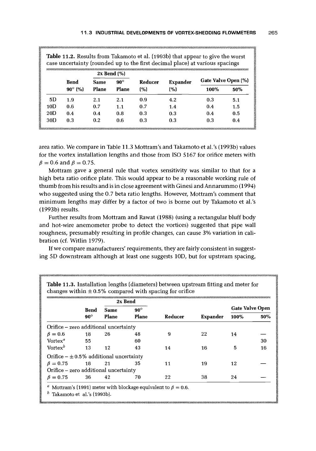
11.3.8 INSTALLATION EFFECTS
Table
11.2
shows
the
change
in
error
for
increasing installation lengths (Takamoto
et al. 1993b). Some
of
the results suggest that
the
error does
not
always decrease with
spacing.
The
worst case
has
been used, from
the
results
of
four meters.
Mottram (1991) commented that
'The
difficulties
of
deciding what should be
the
minimum straight pipe length between
a
given type
of
flowmeter
and a
particular
upstream pipe fitting
are
notorious. Even when
the
geometry
is
standardized,
as is
the case
for the
sharp edged orifice,
the
issue
is
still controversial. This
is due to the
typical shape
of the
envelope enclosing
the
experimental results
for the
calibration
shift plotted against
the
straight pipe length separating
the
meter from
the
upstream
fitting. Minimum straight lengths may differ by
a
factor
of
two."
Mottram
;
s tests were
for
a
vortex meter with
an
area ratio approximately equivalent
to a ft = 0.6
orifice
11.3 INDUSTRIAL DEVELOPMENTS
OF
VORTEX-SHEDDING FLOWMETERS
265
Table 11.2. Results from Takamoto
et
al. (1993b) that appear
to
give
the
worst
case uncertainty (rounded
up to the
first decimal place)
at
various spacings
2x Bend
(%)
5D
10D
20D
30D
Bend
90° (%)
1.9
0.6
0.4
0.3
Same
Plane
2.1
0.7
0.4
0.2
90°
Plane
2.1
1.1
0.8
0.6
Reducer
(%)
0.9
0.7
0.3
0.3
Expander
(%)
4.2
1.4
0.3
0.3
Gate Valve Open (%)
100%
0.3
0.4
0.4
0.3
50%
5.1
1.5
0.5
0.4
area ratio. We compare
in
Table 11.3 Mottram's
and
Takamoto
et
al.'s (1993b) values
for
the
vortex installation lengths
and
those from
ISO 5167 for
orifice meters with
p
= 0.6 and £ = 0.75.
Mottram gave
a
general rule that vortex sensitivity
was
similar
to
that
for a
high beta ratio orifice plate. This would appear
to be a
reasonable working rule
of
thumb from his results
and
is
in
close agreement with Ginesi and Annarummo (1994)
who suggested using
the 0.7
beta ratio lengths. However, Mottram's comment that
minimum lengths
may
differ
by a
factor
of two is
borne
out by
Takamoto
et al.'s
(1993b) results.
Further results from Mottram
and
Rawat (1988) (using
a
rectangular bluff body
and hot-wire anemometer probe
to
detect
the
vortices) suggested that pipe wall
roughness, presumably resulting
in
profile changes,
can
cause 3% variation
in
cali-
bration
(cf.
Witlin 1979).
If
we
compare manufacturers' requirements, they are fairly consistent
in
suggest-
ing
5D
downstream although
at
least
one
suggests
10D, but for
upstream spacing,
Table 11.3. Installation lengths (diameters) between upstream fitting
and
meter
for
changes within
±
0.5% compared with spacing
for
orifice
2x Bend
Bend Same 90°
90° Plane Plane Reducer
Gate Valve Open
Expander 100%
22
16
19
38
14
5
12
24
50%
30
16
—
Orifice
-
zero additional uncertainty
£
= 0.6 18 26 48 9
Vortex
a
55 60
Vortex
6
13 12 43 14
Orifice
- ±
0.5% additional uncertainty
£
= 0.75 18 21 35 11
Orifice
-
zero additional uncertainty
£
= 0.75 36 42 70 22
a
Mottram's (1991) meter with blockage equivalent
to £ = 0.6.
b
Takamoto
et al.'s
(1993b).
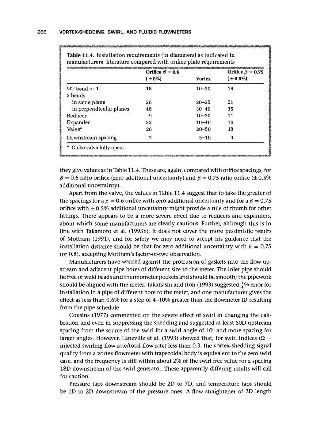
266 VORTEX-SHEDDING, SWIRL, AND FLUIDIC FLOWMETERS
Table 11.4. Installation requirements (in
manufacturers' literature compared with
90° bend or T
2
bends
in same plane
in perpendicular planes
Reducer
Expander
Valve
a
Downstream spacing
Orifice
(3 =
(±0%)
18
26
48
9
22
26
7
diameters) as indicated in
orifice plate requirements
=
0.6
Vortex
10-20
20-25
30-40
10-20
10-40
20-50
5-10
Orifice
(3
= 0.75
(±0.5%)
18
21
35
11
19
18
4
a
Globe valve fully open.
they give values as in Table
11.4.
These are, again, compared with orifice spacings, for
p = 0.6 ratio orifice (zero additional uncertainty) and p = 0.75 ratio orifice
(±0.5%
additional uncertainty).
Apart from the valve, the values in Table 11.4 suggest that to take the greater of
the spacings for a p = 0.6 orifice with zero additional uncertainty and for a ft = 0.75
orifice with ±0.5% additional uncertainty might provide a rule of thumb for other
fittings. There appears to be a more severe effect due to reducers and expanders,
about which some manufacturers are clearly cautious. Further, although this is in
line with Takamoto et al. (1993b), it does not cover the more pessimistic results
of Mottram (1991), and for safety we may need to accept his guidance that the
installation distance should be that for zero additional uncertainty with p = 0.75
(or 0.8), accepting Mottram's factor-of-two observation.
Manufacturers have warned against the protrusion of gaskets into the flow up-
stream and adjacent pipe bores of different size to the meter. The inlet pipe should
be free of weld beads and thermometer pockets and should be smooth; the pipework
should be aligned with the meter. Takahashi and Itoh (1993) suggested \% error for
installation in a pipe of different bore to the meter, and one manufacturer gives the
effect as less than 0.6% for a step of 4-10% greater than the flowmeter ID resulting
from the pipe schedule.
Cousins (1977) commented on the severe effect of swirl in changing the cali-
bration and even in suppressing the shedding and suggested at least 50D upstream
spacing from the source of the swirl for a swirl angle of 10° and more spacing for
larger angles. However, Laneville et al. (1993) showed that, for swirl indices (Q =
injected swirling flow rate/total flow rate) less than 0.3, the vortex-shedding signal
quality from a vortex flowmeter with trapezoidal body is equivalent to the zero swirl
case,
and the frequency is still within about 2% of the swirl free value for a spacing
18D downstream of the swirl generator. These apparently differing results will call
for caution.
Pressure taps downstream should be 2D to 7D, and temperature taps should
be ID to 2D downstream of the pressure ones. A flow straightener of 2D length