Baker R.C. Flow Measurement Handbook: Industrial Designs, Operating Principles, Performance, and Applications
Подождите немного. Документ загружается.

17.7 APPLICATIONS, ADVANTAGES, DISADVANTAGES, AND COST CONSIDERATIONS 417
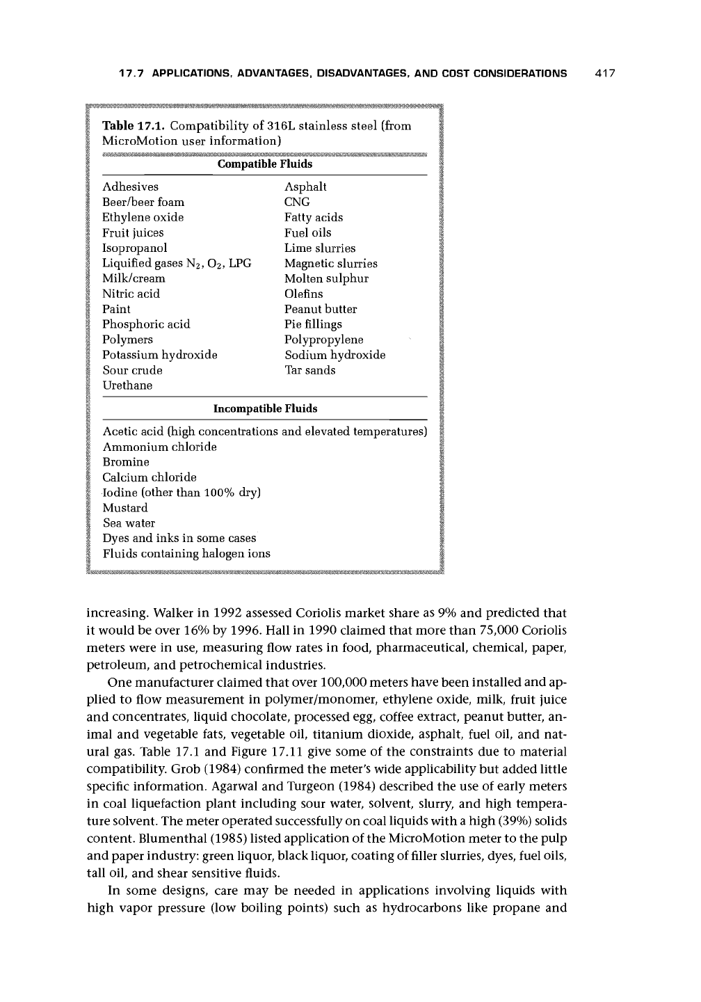
Table 17.1. Compatibility of 316L stainless steel (from
MicroMotion user information)
Compatible Fluids
Adhesives Asphalt
Beer/beer foam CNG
Ethylene oxide Fatty acids
Fruit juices Fuel oils
Isopropanol Lime slurries
Liquified gases N
2
, O
2
, LPG Magnetic slurries
Milk/cream Molten sulphur
Nitric acid Olefms
Paint Peanut butter
Phosphoric acid Pie fillings
Polymers Polypropylene
Potassium hydroxide Sodium hydroxide
Sour crude Tar sands
Urethane
Incompatible Fluids
Acetic acid (high concentrations and elevated temperatures)
Ammonium chloride
Bromine
Calcium chloride
Iodine (other than 100% dry)
Mustard
Sea water
Dyes and inks in some cases
Fluids containing halogen ions
increasing. Walker in 1992 assessed Coriolis market share as 9% and predicted that
it would be over 16% by 1996. Hall in 1990 claimed that more than 75,000 Coriolis
meters were in use, measuring flow rates in food, pharmaceutical, chemical, paper,
petroleum, and petrochemical industries.
One manufacturer claimed that over 100,000 meters have been installed and ap-
plied to flow measurement in polymer/monomer, ethylene oxide, milk, fruit juice
and concentrates, liquid chocolate, processed egg, coffee extract, peanut butter, an-
imal and vegetable fats, vegetable oil, titanium dioxide, asphalt, fuel oil, and nat-
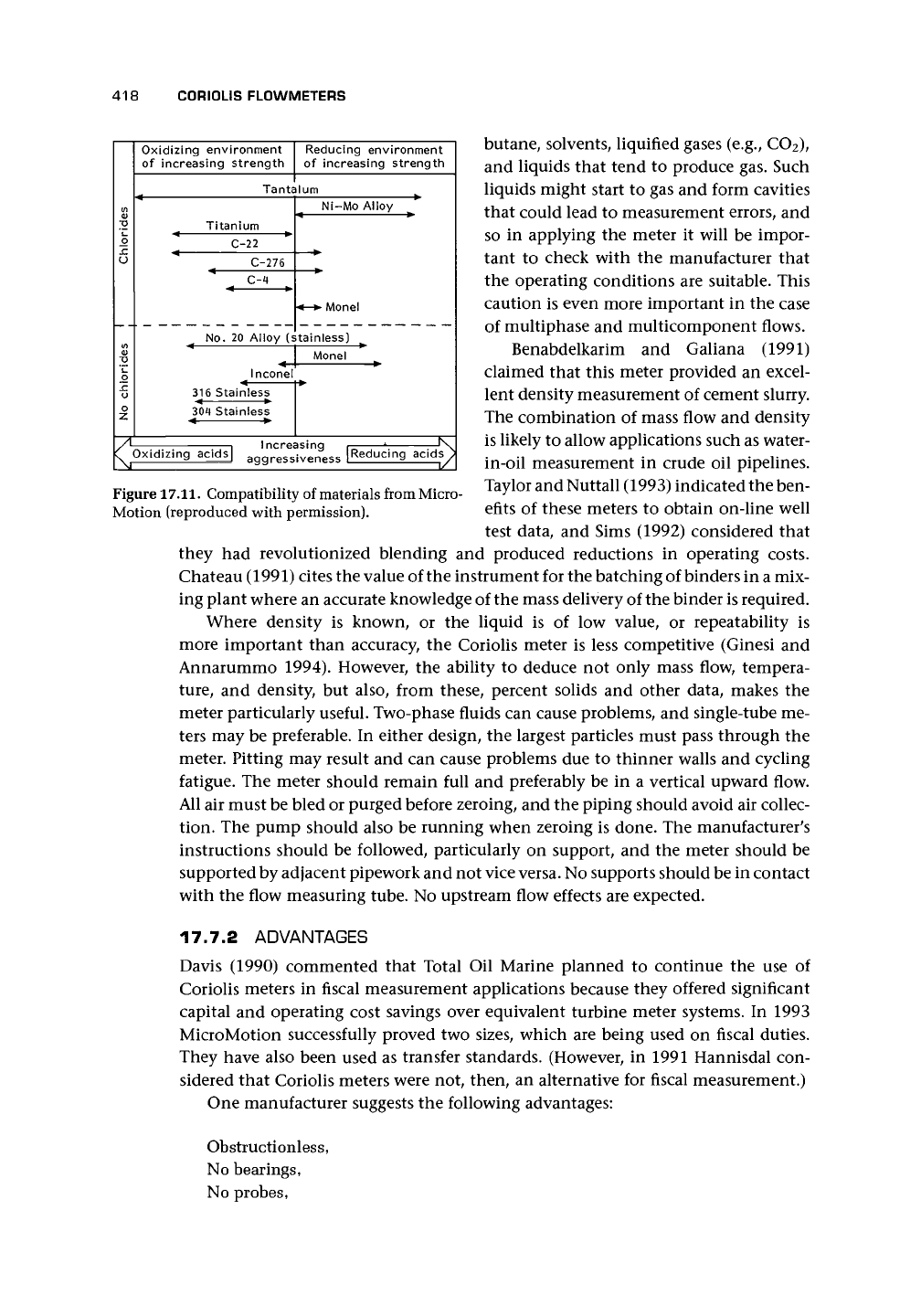
ural gas. Table 17.1 and Figure 17.11 give some of the constraints due to material
compatibility. Grob (1984) confirmed the meter's wide applicability but added little
specific information. Agarwal and Turgeon (1984) described the use of early meters
in coal liquefaction plant including sour water, solvent, slurry, and high tempera-
ture solvent. The meter operated successfully on coal liquids with a high (39%) solids
content. Blumenthal (1985) listed application of the MicroMotion meter to the pulp
and paper industry: green liquor, black liquor, coating of filler slurries, dyes, fuel oils,
tall oil, and shear sensitive fluids.
In some designs, care may be needed in applications involving liquids with
high vapor pressure (low boiling points) such as hydrocarbons like propane and
418
CORIOLIS FLOWMETERS
Oxidizing environment
of increasing strength
Tantalum
Titanium
C-22
C-276
C-4
Reducing environment
of increasing strength
Ni-Mo Alloy
• Monel
No.
20 Alloy (stainless)
Inconel
316 Stainless
< •
304 Stainless
Oxidizing acids]
Increasing
aggressiveness
Reducing acids
Figure
17.11.
Compatibility of materials from Micro-
Motion (reproduced with permission).
butane, solvents, liquified gases (e.g., CO2),
and liquids that tend to produce gas. Such
liquids might start to gas and form cavities
that could lead to measurement errors, and
so in applying the meter it will be impor-
tant to check with the manufacturer that
the operating conditions are suitable. This
caution is even more important in the case
of multiphase and multicomponent flows.
Benabdelkarim and Galiana (1991)
claimed that this meter provided an excel-
lent density measurement of cement slurry.
The combination of mass flow and density
is likely to allow applications such as water-
in-oil measurement in crude oil pipelines.
Taylor and Nuttall (1993) indicated the ben-
efits of these meters to obtain on-line well
test data, and Sims (1992) considered that
they had revolutionized blending and produced reductions in operating costs.
Chateau (1991) cites the value of the instrument for the batching of binders in a mix-
ing plant where an accurate knowledge of the mass delivery of the binder is required.
Where density is known, or the liquid is of low value, or repeatability is
more important than accuracy, the Coriolis meter is less competitive (Ginesi and
Annarummo 1994). However, the ability to deduce not only mass flow, tempera-
ture,
and density, but also, from these, percent solids and other data, makes the
meter particularly useful. Two-phase fluids can cause problems, and single-tube me-
ters may be preferable. In either design, the largest particles must pass through the
meter. Pitting may result and can cause problems due to thinner walls and cycling
fatigue. The meter should remain full and preferably be in a vertical upward flow.
All air must be bled or purged before zeroing, and the piping should avoid air collec-
tion. The pump should also be running when zeroing is done. The manufacturer's
instructions should be followed, particularly on support, and the meter should be
supported by adjacent pipework and not vice
versa.
No supports should be in contact
with the flow measuring tube. No upstream flow effects are expected.
17.7.2 ADVANTAGES
Davis (1990) commented that Total Oil Marine planned to continue the use of
Coriolis meters in fiscal measurement applications because they offered significant
capital and operating cost savings over equivalent turbine meter systems. In 1993
MicroMotion successfully proved two sizes, which are being used on fiscal duties.
They have also been used as transfer standards. (However, in 1991 Hannisdal con-
sidered that Coriolis meters were not, then, an alternative for fiscal measurement.)
One manufacturer suggests the following advantages:
Obstructionless,
No bearings,
No probes,
17.7 APPLICATIONS, ADVANTAGES, DISADVANTAGES, AND COST CONSIDERATIONS 419
Compact design (space saving),
Low power consumption,
Suitability for steam cleaning,
Suitability for bidirectional flow,
Low maintenance, and
Sanitary design.
Cascetta et al. (1992) added to this list their wide range and high accuracy, com-
parable to that of the best volumetric flowmeters, and Cascetta and Vigo (1988)
added true mass flow measurement of all liquids, slurries, and foams.
17.7.3 DISADVANTAGES
Robinson (1986) recorded some of the early limitations (e.g., reduced performance
above about 120°C) and problems (e.g., tube failure) from a survey of process indus-
try users. He also remarked on the problems of cleaning due to pipe configuration.
Cascetta et al. (1989a) also suggested other limitations such as difficult maintenance
(cleaning and repairing) in the case of clogging of sensor tubes when difficult flu-
ids such as slurries are used; limited temperature range and incomplete temperature
compensation; and the effects of stress, creep, etc. In addition, Cascetta and Vigo
(1988) listed high pressure loss, high initial cost, spring constant temperature sensi-
tivity, suitability for only very high pressure gases, and calibration needed if density
of liquid differs substantially from that of calibration fluid.
They may, also, be in competition with ultrasonic multipath meters for volumet-
ric custody transfer for larger (greater than 100 mm) sizes.
Walker (1992) suggested that the meters still had limitations for some hazardous
environments, might need secondary containment, and might be limited by pressure
drop and sensitivity to changes in temperature and pressure and to pipe vibration.
He also identified cost as a limitation. He was optimistic about overcoming many of
these limitations.
17.7.4 COST CONSIDERATIONS
The initial cost of these meters appears to be significantly greater than most other
meter technologies. It is therefore necessary for the prospective user to assess the
appropriateness of the meter for a specific application in terms of
a. initial instrument cost compared with value of product being metered;
b.
cost of installation including any necessary pipework changes in orientation;
c. cost of operation, maintenance, and regular servicing;
d. cost of recalibration including
• the adequacy of in situ methods and
• the cost of removal and test stand calibration, as well as any increased uncer-
tainty between test stand calibration and plant performance.
Liu et
al.
(1986), from oil field experience, found significant capital and operating
cost savings compared with a more conventional approach, and this appears to be
confirmed by Robinson's (1986) survey, which suggested that, after 3 years these
meters are more economical than positive displacement meters.
420 C0RI0LIS FLOWMETERS
17.8 CHAPTER CONCLUSIONS
This chapter was initially written prior to 1994, but material that I have added sug-
gests that the commercial developments have moved ahead of the published material
on test programs.
The meter lends itself to the use of sophisticated computer models that take in
the fine detail of the construction and allow for fluid behavior, compressibility, ho-
mogeneity, and other features. As suggested in Chapter 20, the optimization of this
model should also introduce factors relating to the precision of the manufacturing
options because these are likely to have an influence on final instrument perfor-
mance. Combined with new materials, this should lead to production methods that
provide an increasingly high quality product with wide applicability.
These meters are, clearly, most at home with single-phase liquid flows, and we
should expect to see uncertainty of the ±0.05% level claimed increasingly widely
for 30:1 turndown or greater.
For gases, the scene does not appear so clear. On the one hand, the meter is likely
to be in competition with ultrasonic and thermal techniques. Even though neither
of these offers direct mass flow, both approach it and are likely to be considerably
less costly. On the other hand, there are various questions raised in the literature
about the accuracy of a gas Coriolis meter. Effects due to compressibility and other
features of the gas could mean that, for the highest accuracy, the meter becomes
sensitive to type of gas.
For two or more components in the flow, there are clear problems in the use of
these meters, although claims are made for their use in certain slurries and other
flows. Fundamentally, this is due to the possibility that the components can move
relative to each other. Relative motion should be essentially eliminated if the phases
are of similar density.
The meter has developed from the U-tube designs that have been so successful,
through various configurations to the very significant development of the single-
tube meter (cf. Stansfeld et
al.
1988 and Harrie 1991 for details of an early design that
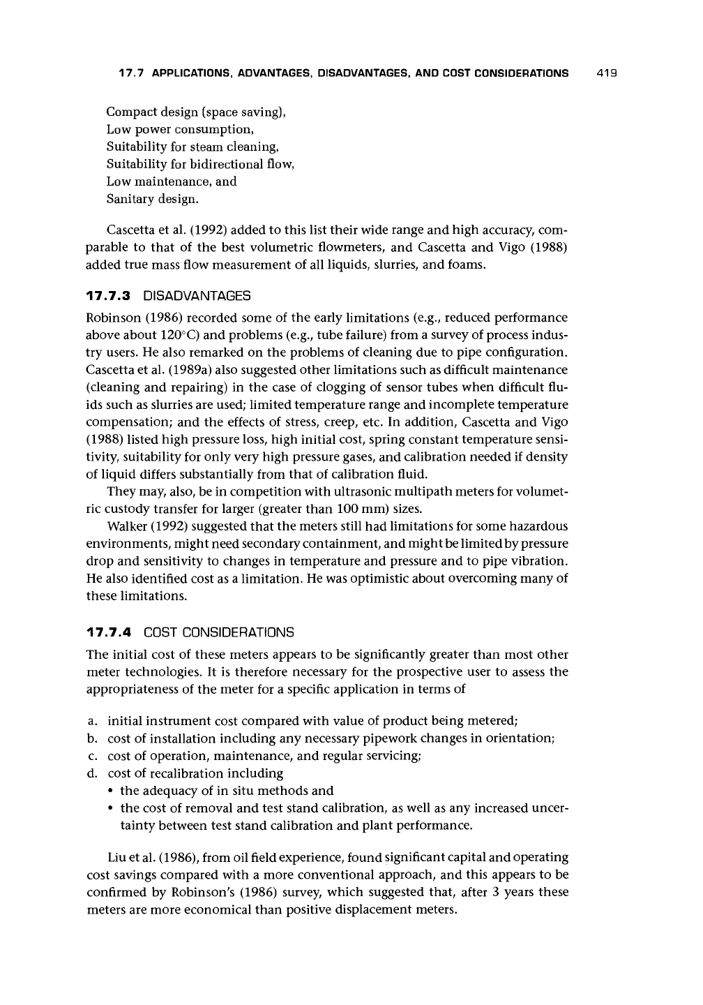
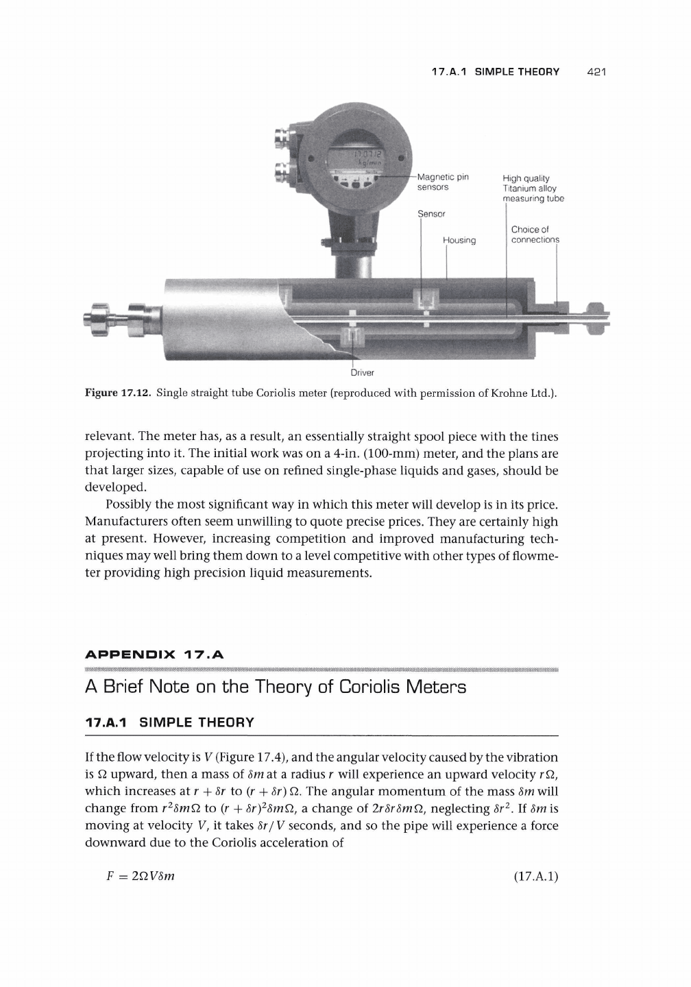
appears to have been withdrawn). Krohne's single straight tube design (Figure 17.12;
Hussain and Farrant 1994), which also incorporates a compensation cylinder in a
floating mode, represents a notable achievement that is already being followed by
other similar designs (Rieder and Drahm 1996, Yamashita 1996). This trend is very
likely to continue, and it should offer a very significant addition to the flowmeter
options for new applications.
What will be the next major development? Some of the recent work suggests that
the single-tube vibration can be in pipe cross-section rather than in longitudinal
bending. Could the next stage be shorter pipes or multiple sensors? Is there a need
to return to the vibrating elements within tubes (Hemp 1994b) or traveling wave
devices as has been suggested in the past? Could tubes be set into torsional motion
with internal segmental arrangements - a cross between the angular momentum
devices and these?
Matthews and Ayling (1992) described a meter that had tines, rather like an
elongated tuning fork, which stretched the length of the meter. The Coriolis prin-
ciple is still valid, and Hemp's work on the oscillating element meter is presumably
17.A.1 SIMPLE THEORY
421
High quality
Titanium alloy
measuring tube
Driver
Figure 17.12. Single straight tube Coriolis meter (reproduced with permission of Krohne Ltd.).
relevant. The meter has, as a result, an essentially straight spool piece with the tines
projecting into it. The initial work was on a 4-in. (100-mm) meter, and the plans are
that larger sizes, capable of use on refined single-phase liquids and gases, should be
developed.
Possibly the most significant way in which this meter will develop is in its price.
Manufacturers often seem unwilling to quote precise prices. They are certainly high
at present. However, increasing competition and improved manufacturing tech-
niques may well bring them down to a level competitive with other types of flowme-
ter providing high precision liquid measurements.
APPENDIX
17.A
mMmmmmmmmmmmmmMMMmMmMmMmm
A Brief Note on the Theory of Coriolis Meters
17.A.1 SIMPLE THEORY
If the flow velocity
is
V (Figure 17.4), and the angular velocity caused by the vibration
is
£2
upward, then a mass of 8m at a radius r will experience an upward velocity
r£2,
which increases at r +
8r
to (r +
8r)
Q.
The angular momentum of the mass
8m
will
change from r
2
8mQ to (r +
8r)
2
8mQ
t
,
a change of 2r8r8mQ, neglecting 8r
2
. If 8m is
moving at velocity V, it takes 8r/V seconds, and so the pipe will experience a force
downward due to the Coriolis acceleration of
F = 2QV8m
(17.A.1)
422 CORIOLIS FLOWMETERS
The other half of the tube will experience an equal and opposite force. Because the
mass of the tube depends on the fluid density 8m=pA8r
f
, the force on each half of
the tube due to length 8r
f
will be equal to 2QpAV8r'. Taking the width of the U-tube
(or the unwrapped length between sensors) as d, the twisting (or distorting) torque
becomes
T = 2KQpAVdl (17.A.2)
where / is the length of each half of the tube, and K allows for the fact that the
distorting Coriolis forces will not form a straight integration. The mass flow is q
m
=
pAV, and the torque can be related to the mass flow rate by
q
m
= T/(2KQdl) (17. A3)
We can now introduce the oscillating motion by putting Q = Q
o
cos
cot,
where
co
is
the driving frequency, and t is time; hence,
T
—
2K£2opAVdlcos
cot
(17.A.4)
If, for the special case of the U-tube, we relate the twisting torque to the twist in the
tube 0 (ignoring damping effects etc.) by
I
s
^l+K
S
O
= T (17.A.5)
where J
s
is the inertia, and K
s
is the spring constant of the U-tube in twisting oscil-
lation, and assume a solution of the form 0 =
6
0
cos
cot,
we obtain an expression for
#o by equating T in Equations (17.A.4) and (17.A.5)
(17.A.6)
where
0
will be in phase with Q. It is then apparent that, while the twisting torque is
at its maximum at the midpoint, the twist is zero at the extremities of the oscillation.
This is illustrated by Blumenthal (1984) and shown in Figure 17.5. The angle of twist
is of order 1/100 degrees.
The free vibration frequency in twisting occurs when K
s
=
I
s
co
2
or
co
s
=
y/K
s
/I
s
(17.A.7)
We can now obtain a relationship between q
m
and 0
0
K
s
(l-co
2
/co
2
)0o
q
m
= —
v J
(17.A.8)
(Damping would prevent the bracket in the numerator from becoming zero when
co
=
co
s
.)
We can go a step farther and relate the twist 0
0
to the time difference for
transit of the two sides of the U-tube. Because the velocity of the U-tube at the sensor
is approximately
£loh
and the displacement due to the twist is
9od,
the time of transit
17.A.2 NOTE ON HEMP'S WEIGHT VECTOR THEORY 423
of the two sides will differ by
T=0
o
d/(Q
o
l) (17.A.9)
Hence the mass flow is given in terms of the transit time difference by
A similar equation will give the relationship for a straight tube. It will be noted that
the actual value of angular velocity
Q
has been eliminated from this expression. The
amplitude of the vibration is typically between 60 fim and
1
mm, and the frequency
is in the range 80-1,100 Hz. The higher frequency tends to be well above most
common mechanical vibrations. In most meters, two tubes oscillate in antiphase
acting like a tuning fork. When flow occurs, the forces created result in phase shifts
in the motion of the two halves of the oscillating tube, and the passage of the
halves of the tube past fixed points will therefore be displaced in time, and the time
difference will be measurable.
An equation similar to Equation (17.A.6) can also be used for the oscillation
without flow, and for this the natural frequency of the tube will be given by
co
u
=
JK
U
/I
U
(17.
A.
11)
where K
u
is the spring constant of the tube in normal oscillation, and J
u
is the inertia
in that plane. Because I
u
is proportional to the mass of the tube and therefore related
to the density of the fluid, the natural frequency can be used to obtain density of
the fluid. In particular, the frequency is little affected by flow so that the density can
be obtained with flow (Raszillier and Raszillier 1991).
17.A.2 NOTE ON HEMP'S WEIGHT VECTOR THEORY
Hemp (1994b) has developed
a
weight vector theory for the Coriolis meter [cf. appen-
dices in electromagnetic (Section 12.A.3), ultrasonic (Section 13.A.3), and thermal
(Section 15.A.5) chapters]. The flowmeter signal is given by
A0=
[v-Wdv
(17.
A.
12)
where A0 is the phase difference between the total velocities at the two sensing
points. The weight vector is then given by
W = -/
where v
(1)
and v
(2)
are oscillatory velocity fields set up in the stationary fluid by the
driving transducer and by equal and opposite unit alternating forces applied at the
sensing points. (See the last paragraph of the fourth section of Hemp 1994b.)
Hemp commented that the theory had been applied at that date (1994b) only
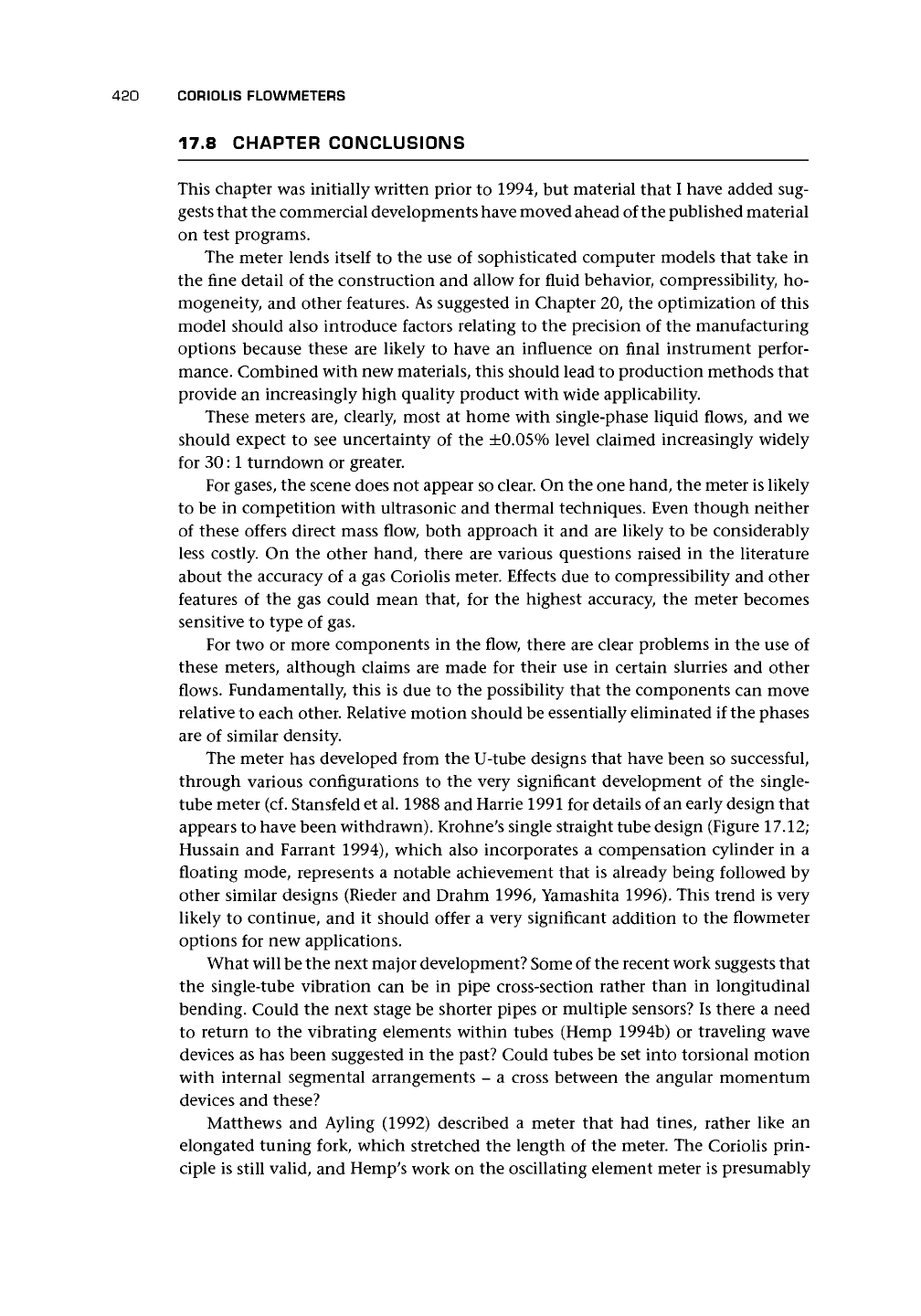
to two relatively simple flowmeter configurations. The first was for a U-tube meter
424
CORIOLIS FLOWMETERS
Axis 1
Axis 2
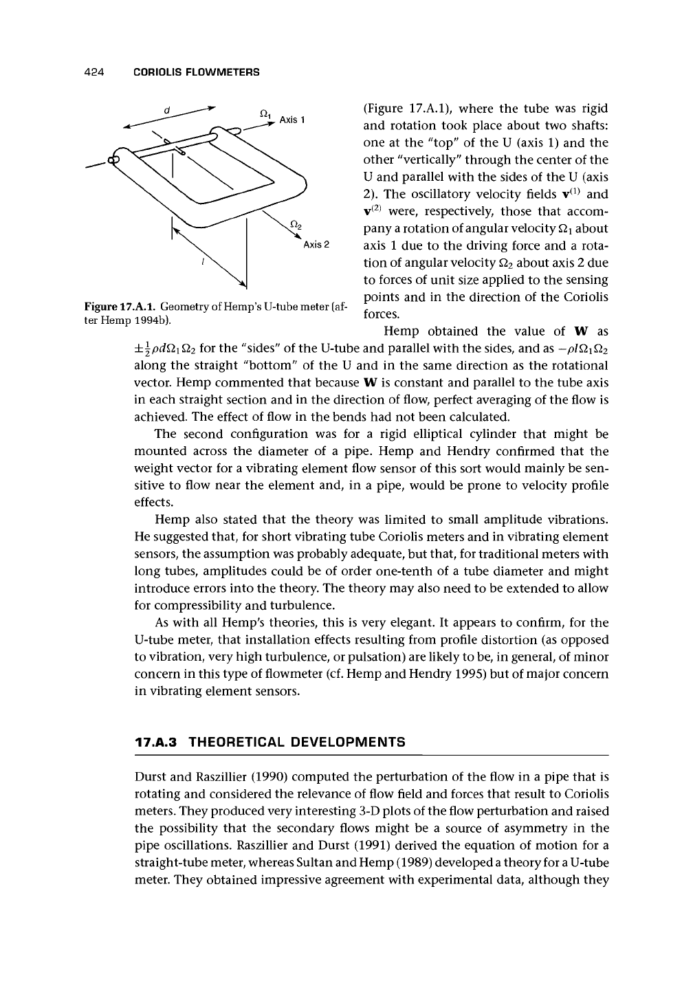
Figure 17.A.1. Geometry of Hemp's U-tube meter (af-
ter Hemp 1994b).
(Figure 17.A.1), where the tube was rigid
and rotation took place about two shafts:
one at the "top" of the U (axis 1) and the
other "vertically" through the center of the
U and parallel with the sides of the U (axis
2).
The oscillatory velocity fields v
(1)
and
v
(2)
were, respectively, those that accom-
pany a rotation of angular velocity
Qi
about
axis 1 due to the driving force and a rota-
tion of angular velocity Q
2
about axis 2 due
to forces of unit size applied to the sensing
points and in the direction of the Coriolis
forces.
Hemp obtained the value of W as
for the "sides" of the U-tube and parallel with the sides, and as — plQiQ
2
along the straight "bottom" of the U and in the same direction as the rotational
vector. Hemp commented that because W is constant and parallel to the tube axis
in each straight section and in the direction of flow, perfect averaging of the flow is
achieved. The effect of flow in the bends had not been calculated.
The second configuration was for a rigid elliptical cylinder that might be
mounted across the diameter of a pipe. Hemp and Hendry confirmed that the
weight vector for a vibrating element flow sensor of this sort would mainly be sen-
sitive to flow near the element and, in a pipe, would be prone to velocity profile
effects.
Hemp also stated that the theory was limited to small amplitude vibrations.
He suggested that, for short vibrating tube Coriolis meters and in vibrating element
sensors, the assumption was probably adequate, but that, for traditional meters with
long tubes, amplitudes could be of order one-tenth of a tube diameter and might
introduce errors into the theory. The theory may also need to be extended to allow
for compressibility and turbulence.
As with all Hemp's theories, this is very elegant. It appears to confirm, for the
U-tube meter, that installation effects resulting from profile distortion (as opposed
to vibration, very high turbulence, or pulsation) are likely to be, in general, of minor
concern in this type of flowmeter (cf. Hemp and Hendry 1995) but of major concern
in vibrating element sensors.
17.A.3 THEORETICAL DEVELOPMENTS
Durst and Raszillier (1990) computed the perturbation of the flow in a pipe that is
rotating and considered the relevance of flow field and forces that result to Coriolis
meters. They produced very interesting 3-D plots of the flow perturbation and raised
the possibility that the secondary flows might be a source of asymmetry in the
pipe oscillations. Raszillier and Durst (1991) derived the equation of motion for a
straight-tube meter, whereas Sultan and Hemp (1989) developed
a
theory for
a
U-tube
meter. They obtained impressive agreement with experimental data, although they
17.A.3 THEORETICAL DEVELOPMENTS 425
indicated that there were various limitations of the theory and that further areas of
work were still needed. Raszillier and Raszillier (1991) used dimensional arguments
to show the possible interdependence of velocity and density. John Hemp (private
communication July 1994) commented that the very useful results of this reference
include general expressions for time delay and frequency, showing how they depend
on various meter parameters such as Young's modulus and length, and estimates of
the order of effects of fluid density on time delay and natural frequency. Raszillier
et al. (1993) suggested that, by influencing the vibration spectrum, the sensitivity
of the instrument may be increased. Raszillier et al. (1994) investigated the effect of
a concentrated mass at the middle of the Coriolis pipe segment as required for the
purpose of symmetric excitation of the vibration. The flowmeter factor was found
to be almost independent of the mass up to fairly high values compared with the
mass of the fluid-filled pipe segment, although the frequency of the fundamental
mode is strongly influenced. Lange et al. (1994) examined the effect of detector
masses on the calibration of Coriolis flowmeters. They showed that the position of
the detectors must be chosen with care because it may have implications for the
accuracy to which the calibration of the meter remains independent of the fluid
density. The calibration becomes dependent on fluid density if the detector masses
are not negligible compared with the pipe
mass.
They suggested the most appropriate
positions for the first symmetric and the first antisymmetric vibration modes (cf.
Sultan 1992).
Hemp's (1988) reciprocity concept for flowmeters to reduce zero drift errors may
also be applied to Coriolis meters.
Watt (1991) used a simple Coriolis force model and applied it to obtain the
tube distortion for an Endress and Hauser ra-point type tube using a finite element
computer analysis. His work confirmed that the highest stresses were around the
midpoint where the tube is driven and at each end. He makes the point that the
Coriolis distortion of the tube will modify the Coriolis forces compared with a tube
in pure bending.
Hemp and Sultan (1989) explained the concept of effective mass of bubbles in
a liquid and calculated the expected error. Compared with Grumski and Bajura's
(1984) measurements, the theory overestimated the error possibly due to interaction
between bubbles.
Pawlas and Pankratz (1994) discussed their CFD analysis of flow in Coriolis tubes
and outlined their plans for an iterative approach to linking structural analysis of the
rotation of the flow tube with fluid mechanics analysis to obtain a spatially varying
rate of rotation and hence the pressure distribution on the tube wall, in part due to
Coriolis forces.
Hemp (1996) used dimensional analysis (cf. Raszillier and Raszillier 1991) to ex-
plore the design requirements if the meter was to be used with low mass flow rates
(e.g., when applied to gases near normal temperature and pressure). His findings
suggest that the most appropriate type of sensing transducer in this case is the dis-
placement transducer and that the likely requirements, keeping maximum strain
unchanged and retaining similarity in layout, will be a reduction in tube diameter
to one-third or so and wall thickness to about one-quarter while retaining the same
length of pipe.
426 CORIOLIS FLOWMETERS
Keita (1994) provided a very useful discussion of the various equations used to
predict the behavior and the sources of calibration shift in Coriolis meters for
gas
flow
measurement. He concluded that the main contribution to the shift in the meter
factor was due to pressure, that the compressibility effects were very small and partly
compensate for the pressure effect, and that, despite the high resonance frequency
of straight-tube flowmeters, they were suitable for gas flow measurement.