Balakumar Balachandran, Magrab E.B. Vibrations
Подождите немного. Документ загружается.

which can cause the shaft to vibrate in an undesirable manner. In this section,
we shall model such a system and analyze it to determine the factors that in-
fluence its vibratory motion.
34
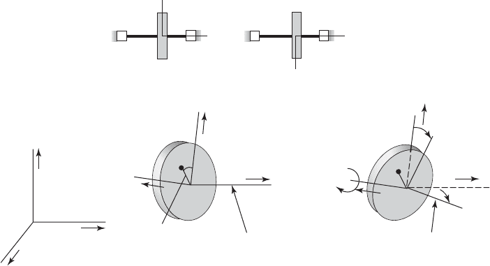
Consider a massless rotating shaft carrying a disk of mass m, as shown in
Figure 7.22a. We ignore damping effects in this analysis, and assume “small”
angular motions of the disk, as will be explained subsequently. The external
forces and moments that act on the disk also will be discussed later. Referring
to Figure 7.22b, the center of mass of the disk is located at P, which is located
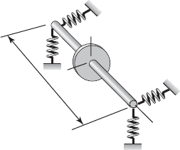
at a distance e from the center of the shaft C. In addition, the shaft is assumed
to be supported at its left and right ends by pairs of translational springs in the
x and y directions, as shown in Figure 7.23.
Kinematics and Kinetic Energy
As shown in Figure 7.22b, the unit vectors i, j, and k are directed along the
O-x, O-y, and O-z directions, and point O is fixed in an inertial reference frame.
The unit vectors i, j, and k are directed along the C-x, C-y, and C-z direc-
tions, where C is the geometric center of the disk. The static unbalance angle is
410 CHAPTER 7 Multiple Degree-of-Freedom Systems
34
The derivation of the equations of motion follows the treatment provided in G. Genta, 1995,
ibid.
z
x
m
z
y
m
(a)
(b)
i
j
k
x
z
y
O
⇒
x
i
j
y
z
k
C
P
|R
PC
|
Rotation axis
x
i
j
y
z
k
C
P
χ
Axis of symmetry
FIGURE 7.22
(a) Rotating shaft with disk showing supports and the x, y, and z axes of the inertial reference frame; and (b) transformation from
Oxyz to disk fixed frame Cxyz and the rotation x that accounts for the angular imbalance. An Euler-angle sequence of a w rotation
about the O-x axis, followed by a u rotation about the intermediate y axis, and a subsequent rotation of q about the O-z axis takes
one from the Oxyz frame to the Cxyz frame shown in Figure 7.22b. A subsequent rotation x about the C-y axis takes one to the
principal axes of the disk.
a and x is the angular imbalance between the axis of symmetry and the rota-
tion axis, which is along the C-z direction. The axis of symmetry is shown in
Figure 7.22b. In the absence of this angular imbalance x, the principal axes of
the disk coincide with the C-x, C-y, and C-z axes.
To obtain the equations of motion, we use Lagrange’s equations. We first
construct the kinetic energy and potential energy of the system. In order to go
from the Oxyz frame to the Cxyz frame, an Euler-angle sequence consist-
ing of a w rotation about the O-x axis, followed by a u rotation about the in-
termediate y axis, and a subsequent rotation of q about the O-z or C-z axis is
used. For an arbitrary rotation b about each of these three axes, we can define
the rotation matrices as follows.
35
1. For a rotation b about the O-x axis,
(7.113a)
2. For a rotation b about the intermediate y axis,
(7.113b)
3. For a rotation b about the O-z axis,
(7.113c)
Making use of the rotation matrices given in Eq. (7.113), one can relate
the unit vectors i, j, and k to the unit vectors i, j, and k as
(7.114)
where we have assumed “small” rotation angles w and u about zero in arriv-
ing at the composite rotation matrix. In addition, if it is assumed that the static
C
cos 1q a2 wu cos 1q a 2 sin 1q a 2 w sin 1q a2 u cos 1q a2
sin 1q a2 wu sin 1q a2 cos 1q a2
w cos 1q a2 u sin 1q a 2
u w 1
Sc
i
j
k
s
c
i¿
j¿
k¿
s 3R
z
1q a243R
y
1u 243R
x
1w 24c
i
j
k
s
3R
z
1b 24 C
cos b sin b 0
sin b cos b 0
001
S
3R
y
1b 24 C
cos b 0 sin b
01 0
sin b 0 cos b
S
3R
x
1b 24 C
10 0
0 cos b sin b
0 sin b cos b
S
7.4 Rotating Shafts on Flexible Supports 411
35
D. T. Greenwood, 1988, ibid.
FIGURE 7.23
Definitions of the stiffness constants
representing the stiffness of the
supports.
k
Lx
k
Ly
k
Rx
k
Ry
z
y
a
L
x
b

unbalance angle a 0 and that we can neglect terms with wu, then Eq.
(7.114) becomes
(7.115)
The position vector from the disk center of mass P to the origin of the
inertial reference frame O is given by
(7.116)
After using the first row of Eq. (7.115) in Eq. (7.116), we obtain
(7.117)
It is recalled that q(t) is the rotation angle corresponding to the rotation speed
of the shaft. We obtain the velocity of the center of mass P with respect to the
O by taking the time derivative of Eq. (7.117); this leads to
(7.118a)
The z-component of the velocity contains two terms. The first term is the ve-
locity of the point C in the axial direction. The second term is the velocity due
to the eccentricity and rotations of the cross section of the shaft. If e is small,
then this second term can be neglected in comparison to the first term. This
leads to
(7.118b)
Then, the translational kinetic energy is given by
(7.119)
To determine the rotational kinetic energy, we need to determine the an-
gular speeds about the axis of symmetry fixed in the disk. First, noting that
a 0, we determine the angular speeds about the C-x, C-y, and C-z axes
as follows
(7.120) c
w
#
cos qcos u u
#
sin q
w
#
sin qcos u u
#
cos q
w
#
sin u
q
#
s
c
v
X
v
Y
v
Z
s 3R
z
1q 243R
y
1u 24c
w
#
0
0
s 3R
z
1q 24c
0
u
#
0
s c
0
0
q
#
s
1
2
m5x
#
2
y
#
2
z
#
2
e
2
q
#
2
2eq
#
3x
#
sin q y
#
cos q46
T
t
1
2
m1V
PO
#
V
PO
2
V
PO
3x
#
eq
#
sin q4i 3y
#
eq
#
cos q4j z
#
k
3z
#
e11q
#
w u
#
2cos q 1q
#
u w
#
2sin q24k
V
PO
3x
#
eq
#
sin q4i 3y
#
eq
#
cos q4j
1x e cos q2i 1y e sin q 2j 1z ew sin q eu cos q2k
R
PO
xi yj zk e3cos qi sin qj 1w sin q u cos q2k 4
R
PO
R
CO
R
PC
xi yj zk ei¿
•
i¿
j¿
k¿
¶ £
cos q sin qwsin q u cos q
sin q cos qwcos q u sin q
u w 1
§•
i
j
k
¶
412 CHAPTER 7 Multiple Degree-of-Freedom Systems

where the rotation matrices are given by Eq. (7.113). To determine the angu-
lar speeds of the disk about the principal axes of the disk, we need to rotate
the Cxyz frame through the angle x about the C-y axis. This rotation re-
sults in the angular speeds
(7.121)
If it is assumed that x is a “small” rotation about zero and that the rotation an-
gles w and u are “small” rotations about zero as well, then Eq. (7.121) can be
simplified to
(7.122)
The rotational kinetic energy T
r
is obtained from
(7.123)
where J
t
is the principal inertia of the disk about two of the axes in the plane
of the disk and J
p
is the principal inertia of the disk about the third axis. Upon
substituting Eq. (7.122) into Eq. (7.123) and performing the matrix multipli-
cations, we obtain
(7.124)
where, by assuming “small” rotational speeds and , the cubic and higher
terms composed of the products of x, u, , and and their squares have been
neglected. However, the terms containing and are not neglected.
Lagrange’s Equations and Equations of Motion
Next, we use Lagrange’s equations to determine the equations governing the
rigid-body motions of the disk. Since there are no potential energy terms and
no damping, the potential energy V 0, and the damping function D 0 in
Eqs. (7.7). To determine the generalized forces, we note that the forces F
x
, F
y
,
and F
z
are defined along the O-x, O-y, and O-z directions, respectively, and
the moments M
w
, M
u
, and M
q
are defined about the x axis obtained after a w
q
#
2
q
#
w
#
u
#
w
#
u
#
2xq
#
1J
p
J
t
21w
#
cosq u
#
sinq26
1
2
5J
t
1w
#
2
u
#
2
x
2
q
#
2
2 J
p
1q
#
2
2w
#
uq
#
2
T
r
1
2
5J
t
1v
2
1
v
2
2
2 J
p
v
2
3
6
T
r
1
2
5v
1
v
2
v
3
6C
J
t
00
0 J
t
0
00J
p
Sc
v
1
v
2
v
3
s
v
3
x3w
#
cos q u
#
sin q q
#
w
#
u
v
2
w
#
sin q u
#
cos q
v
1
w
#
cos q u
#
sin q xq
#
c
1w
#
cos q cos u u
#
sin q2cos x 1w
#
sin u q
#
2sin x
w
#
sin q cos u u
#
cos q
1w
#
cos q cos u u
#
sin q2sin x 1w
#
sin u q
#
2cos x
s
c
v
1
v
2
v
3
s 3R
y
1x 24c
v
X
v
Y
v
Z
s 3R
y
1x 24c
w
#
cos qcos u u
#
sin q
w
#
sin qcos u u
#
cos q
w
#
sin u
q
#
s
7.4 Rotating Shafts on Flexible Supports 413

rotation about the O-x axis, about the intermediate y axis, and C-z axes, re-
spectively. Thus, the forces are Q
x
F
x
, Q
y
F
y
, and Q
z
F
z
, and the mo-
ments are given by
(7.125)
where we have made use of Eq. (7.113) and also assumed a “small” u rotation
about 0. After using the generalized forces and the generalized moments
given by Eq. (7.125) and noting the dependence of T
t
and T
r
on the different
variables, the Lagrange equations can be written as
(7.126)
After substituting Eqs. (7.119) and (7.123) into Eq. (7.125) and performing
the indicated operations, we obtain the following equations governing the
translational motions
(7.127a)
(7.127b)
(7.127c)
For the rotational motions, we obtain the governing equations
(7.128a)
(7.128b)
(7.128c)
We can substitute for M
q
from Eq. (7.128c) into Eq. (7.128a). We note that
in Eq. (7.128a), M
q
is multiplied by the small angle u. When Eq. (7.128c) is
multiplied by the small angle u, except for the term , all the other terms
can be neglected, since they are higher-order terms. Therefore, Eq. (7.128a)
becomes
(7.129)
If the only external forces acting on the rigid body are those due to the re-
actions of the elastic springs shown in Figure 7.23, then, in general,
(7.130)
and
k
ux
x k
uu
u M
u
k
xx
x k
xu
u F
x
J
t
w
$
J
p
u
#
q
#
x1J
t
J
p
21q
$
cos q q
#
2
sin q2 M
w
J
p
uq
$
M
q
M
w
u
1J
p
J
t
x
2
me
2
2q
$
me1y
$
cos q x
$
sin q2 x1J
p
J
t
21w
$
cos q u
$
sin q2
J
t
u
$
J
p
q
#
w
#
x1J
t
J
p
21q
$
sin q q
#
2
cos q2 M
u
J
t
w
$
J
p
q
$
u J
p
u
#
q
#
x1J
t
J
p
21q
$
cos q q
#
2
sin q2 M
w
M
q
u
mz
$
F
z
my
$
me3q
$
cos q q
#
2
sin q4 F
y
mx
$
me3q
$
sin q q
#
2
cos q4 F
x
d
dt
a
0T
t
0z
#
b
0T
t
0z
F
z
d
dt
a
0T
r
0q
#
b
01T
r
T
t
2
0q
M
q
M
w
u
d
dt
a
0T
t
0y
#
b
0T
t
0y
F
y
d
dt
a
0T
r
0u
#
b
0T
r
0u
M
u
d
dt
a
0T
t
0x
#
b
0T
t
0x
F
x
d
dt
a
0T
r
0w
#
b
0T
r
0w
M
w
M
q
u
c
Q
w
Q
u
Q
q
s 3R
y
1u 24
T
c
M
w
M
u
M
q
s C
cos u 0 sin u
010
sin u 0 cos u
Sc
M
w
M
u
M
q
s c
M
w
M
q
u
M
u
M
q
M
w
u
s
414 CHAPTER 7 Multiple Degree-of-Freedom Systems
(7.131)
where k
ab
are the spring constants for the coupled motion of the system.
The quantities k
xx
and k
yy
represent the stiffness due to translations only of the
shaft in the x and y directions, respectively, and k
ww
and k
uu
represent the stiff-
ness of the system due to rotations only about the corresponding axes, re-
spectively. The quantities k
x
u
, k
u
x
, k
y
w
, and k
wy
represent the stiffness due to the
coupling of translation and rotation of the shaft. Also, from Maxwell’s recip-
rocal theorem, we have that k
xu
k
ux
and k
yw
k
wy
. These spring constants are
determined subsequently.
In view of Eqs. (7.130) and (7.131), Eq. (7.127c) is uncoupled from all
the other equations. In addition, we have already used Eq. (7.128c) to obtain
Eq. (7.129). Thus, there remain four equations that determine the motion of
the system shown in Figure 7.22. After using Eqs. (7.130) and (7.131) in
Eqs. (7.127a), (7.127b), (7.128b), and Eq. (7.129), we arrive at
(7.132)
We now assume that the shaft rotates at constant speed v
s
; that is, q v
s
t.
Then, and , and Eqs. (7.132) become
(7.133a)
(7.133b)
(7.133c)
(7.133d)
The spring constants used in Eqs. (7.133) are determined from a static-
force balance and a static-moment balance. By using a procedure similar to
that shown in Figure 7.5 for “small” u, we find that a force balance along the
O-x direction gives
(7.134)
and that a moment balance in the disk plane yields
(7.135)
where a and b are defined in Figure 7.23. If we drop the terms with velocities
and accelerations from Eqs. (7.133a) and (7.133d) and compare the resulting
equations with Eqs. (7.134) and (7.135), respectively, we see that
(7.136)
k
uu
a
2
k
Lx
b
2
k
Rx
k
xu
k
ux
ak
Lx
bk
Rx
k
xx
k
Lx
k
Rx
1ak
Lx
bk
Rx
2x 1a
2
k
Lx
b
2
k
Rx
2u
M
u
a1x au2k
Lx
b1x bu2k
Rx
1k
Lx
k
Rx
2x 1ak
Lx
bk
Rx
2u
F
x
1x au 2k
Lx
1x bu 2k
Rx
J
t
u
$
J
p
q
#
v
s
k
ux
x k
uu
u xv
2
s
1J
t
J
p
2cos v
s
t
J
t
w
$
J
p
u
#
v
s
k
wy
y k
ww
w xv
2
s
1J
t
J
p
2sin v
s
t
my
$
k
yy
y k
yw
w mev
2
s
sin v
s
t
mx
$
k
xx
x k
xu
u mev
2
s
cos v
s
t
q
$
0q
#
v
s
J
t
u
$
J
p
q
#
w
#
k
ux
x k
uu
u x1J
t
J
p
21q
$
sin q q
#
2
cos q2
J
t
w
$
J
p
u
#
q
#
k
wy
y k
ww
w x1J
t
J
p
21q
$
cos q q
#
2
sin q2
my
$
k
yy
y k
yw
w me3q
$
cos q q
#
2
sin q4
mx
$
k
xx
x k
xu
u me3q
$
sin q q
#
2
cos q4
k
wy
y k
ww
w M
w
k
yy
y k
yw
w F
y
7.4 Rotating Shafts on Flexible Supports 415
In a similar manner, we find that
(7.137)
We shall restrict ourselves to the symmetrical case where k
Lx
k
Rx
k
Ly
k
Ry
k. Then, from Eqs. (7.136) and (7.137), we obtain
(7.138)
where L is the length of the shaft and
(7.139)
We note that A
1
0 when the disk is in the center of the shaft; that is, when
a b. The quantity k
1
represents the stiffness due to translation only, k
3
rep-
resents the stiffness due to rotation only, and k
2
represents the stiffness due to
the coupling of translation and rotation. When the system is restricted to
translate only, then, k
2
k
3
0.
In an attempt to identify key parameters that determine the natural fre-
quencies of the system, we introduce the following quantities
(7.140)
After using Eqs. (7.138) and (7.140) in Eqs. (7.133), we obtain the following
nondimensional form of Eqs. (7.133):
(7.141a)
(7.141b)
(7.141c)
(7.141d)
Here, an over dot indicates the derivative with respect to t. The right-hand
side of the first two equations contains the force components generated by the
unbalance due to the eccentricity between the center of mass of the disk and
the center of disk that lies on the axis of rotation. The right-hand side of the
last two equations contains rotational inertia components associated with the
angular misalignment of the axis of symmetry of the disk with the axis of ro-
tation of the shaft.
J
mt
u
$
J
mp
s
w
#
1A
1
/2 2X 1A
2
/2 2u x
2
s
1J
mt
J
mp
2cos
s
t
J
mt
w
$
J
mp
s
u
#
1A
1
/2 2Y 1A
2
/2 2w x
2
s
1J
mt
J
mp
2sin
s
t
Y
$
Y 1A
1
/2 2w e
ˆ
2
s
sin
s
t
X
$
X 1A
1
/2 2u e
ˆ
2
s
cos
s
t
J
mt
J
t
mL
2
,
J
mp
J
p
mL
2
,
t v
s
t,
e
ˆ
e
L
X x/L,
Y y/L,
v
1
A
k
1
m
,
s
v
s
v
1
A
1
a b
L
and
A
2
a
2
b
2
L
2
k
3
k
uu
k
ww
kL
2
A
2
k
2
k
xu
k
ux
k
yw
k
wy
kLA
1
k
1
k
xx
k
yy
2k
k
ww
a
2
k
Ly
b
2
k
Ry
k
yw
k
wy
ak
Ly
bk
Ry
k
yy
k
Ly
k
Ry
416 CHAPTER 7 Multiple Degree-of-Freedom Systems
Special Cases
Case 1: Translation only When the system only translates in, say, the x di-
rection, then k
2
k
3
0 and Eq. (7.141a) reduces to Eq. (5.63a) without
damping (i.e., when z 0).
Case 2: Translation and rotation in one plane When the system can both
rotate and translate in only one plane, say the CX-CZ plane and the shaft is
not spinning, then Y w
s
0 and Eqs. (7.141a) and (7.141d) reduce,
after notational differences are accounted for and damping is omitted, to
Eqs. (b) of Example 7.16.
Case 3: Centrally located mass When the disk is located at the center of the
shaft a b and, therefore, A
1
0. In this case, the Eqs. (7.141a) and (7.141b)
uncouple from each other and from Eqs. (7.141c) and (7.141d). Thus, Eqs.
(7.141a) and (7.141b) become, respectively,
(7.142a)
(7.142b)
Each of Eqs. (7.142) is analogous to the equation obtained for a single
degree-of-freedom system subjected to a rotating unbalanced load given by
Eq. (5.63a) when z 0 in Eq. (5.63a). The solutions to Eqs. (7.142a) and
(7.142b) are, respectively,
(7.143a)
and
(7.143b)
The nondimensional displacement of the center of the disk denoted by r is
given by
(7.144)
which, for a given value of Ω
s
, is a constant. Thus, the displaced center of the
shaft rotates in a circle of radius r about the point O fixed in the inertial ref-
erence frame. This type of response is known as synchronous whirl. When
s
1; that is, when
s
1
, then the shaft is said to be rotating at its criti-
cal speed.
General Solution
To obtain an analytical solution to Eqs. (7.140), we introduce the following
complex variables
36
r 2X
2
Y
2
e
ˆ
2
s
1
2
s
Y
e
ˆ
2
s
1
2
s
sin
s
t
X
e
ˆ
2
s
1
2
s
cos
s
t
Y
$
Y e
ˆ
2
s
sin
s
t
X
$
X e
ˆ
2
s
cos
s
t
7.4 Rotating Shafts on Flexible Supports 417
36
See Appendix F.
(7.145)
We multiply Eqs. (7.141b) and (7.141c) by j and then add Eqs. (7.141a) and
the modified (7.141b) together and subtract the modified Eq. (7.141c) from
Eq. (7.141d) and use Eq. (7.145) to obtain
(7.146)
Free whirling of an undamped system The free whirling of an undamped
system can be obtained by setting in Eq. (7.146) and assuming
that h and j are of the form
(7.147)
where v/v
1
and v is the vibration frequency. After using Eqs. (7.147)
in Eqs. (7.146), we arrive at
(7.148)
where
3D
ˆ
c
4 c
1
2
A
1
/2
A
1
/2 A
2
/2 J
mt
2
J
mp
s
d
and
5Z
o
6 e
j
o
h
o
f
3D
ˆ
c
5Z
o
6 0
h h
o
e
jt
®
o
e
jt
j£
o
e
jt
j j
o
e
jt
X
o
e
jt
jY
o
e
jt
e
ˆ
x 0
J
mt
h
$
jJ
mp
s
h
#
A
1
j/2 A
2
h/2 x1J
mt
J
mp
2
2
s
e
j
s
t
j
$
j A
1
h/2 e
ˆ
2
s
e
j
s
t
h u jw
j X jY
418 CHAPTER 7 Multiple Degree-of-Freedom Systems
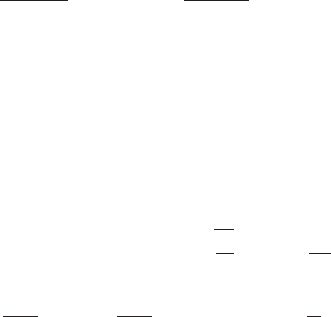
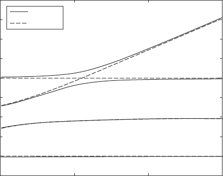
3
a/L 0.1
a/L 0.5
2.5
2
1.5
1
0.5
0
0.5
1
1.5
0 0.5 1
s
1.5
FIGURE 7.24
Campbell diagram for a rigid shaft rotating at
s
for two different locations of the disk with
J
mt
3 and J
mp
5.
The natural frequencies
n
are those values that satisfy ; that is,
when they are the solutions to
(7.149)
After solving numerically
37
for the four roots of Eq. (7.149) as a function of
s
, we obtain the results shown in Figure 7.24. This diagram is referred to as
a Campbell diagram. For each value of
s
, two of these roots are positive and
the other two are negative. The positive roots correspond to whirling in the
forward direction, and the negative roots correspond to whirling in the reverse
or backward direction.
7.5 STABILITY
Extending the notion of bounded stability presented in Section 4.3, a linear
multi-degree-of-freedom system described by the generalized coordinates x
1
,
x
2
, . . ., x
N
and subjected to finite initial conditions and finite forcing functions
is said to be stable if
(7.150)
where A has a finite value. This is a boundedness condition, which requires
the system response {x} to be bounded for bounded system inputs. If this con-
dition is not satisfied, then the system is said to be unstable.
EXAMPLE 7.25
Stability of an undamped system with gyroscopic forces
We revisit Examples 7.4 and 7.23 and determine under what conditions the
gyro-sensor is unstable during free oscillations at angular speeds v
z
. Based on
Eq. (7.150), we need to determine if
(a)
is true. For free oscillations of the gyro-sensor based on the discussion of Sec-
tion 7.3.3, the motion is described by
(b)
where l are the eigenvalues. If one or more of the eigenvalues have a positive
real part, then Eq. (a) will not be true for all time. We can use this as a basis
e
x1t 2
y1t 2
f e
X
Y
fe
lt
2x
2
y
2
A for all time
‘ 5x6‘ 2x
2
1
x
2
2
p
x
2
N
A for all time
J
mt
4
J
mp
s
3
1J
mt
A
2
/2 2
2
J
mp
s
A
2
/2 A
2
1
/4 0
0D
ˆ
c
0 0
7.5 Stability 419
37
The MATLAB function roots was used.