Bhushan B. Handbook of Micro/Nano Tribology, Second Edition
Подождите немного. Документ загружается.

© 1999 by CRC Press LLC
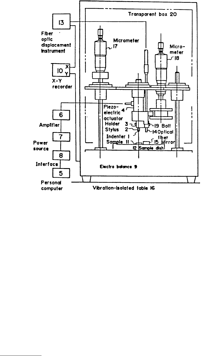
optical fiber and the mirror is adjusted to a region with linearity by a micrometer (18). A bolt (19) is
loosened in this adjustment and is fastened after the adjustment to make the optical fiber move together
with the indenter. Measurement begins with increasing the voltage applied to the piezoelectric actuator.
After the indenter touches and penetrates the sample (loading process), the voltage applied to the
piezoelectric actuator is reduced (unloading process).
10.2.2.6 Ecole Central of Lyon Design
The surface force apparatus commonly used for molecular rheology of thin lubricant films, was modified
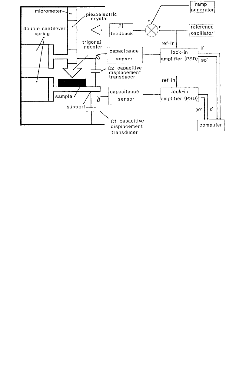
by Loubet et al. (1993) to conduct nanoindentation studies. Figure 10.9 shows the schematic of their
nanoindenter design which uses piezoelectric crystal for indenter motion and two capacitance probes
for measurement of the load and the displacement. The indenter is fixed to the piezoelectric crystal and
the specimen is supported by double-cantilever spring whose stiffness can be adjusted between 4
¥
10
3
and 6
¥
10
6
N/m. The double-cantilever spring prevents the surfaces from rolling and shearing during
loading. Two capacitance displacement probes are used. One of the capacitive sensor C
1
measures the
elastic deflection of the cantilever and thus the force transmitted to the sample. Another capacitive sensor
C
2
measures the relative displacement between the indenter and the sample (or indentation depth).
In an indentation experiment, for the coarse approach, the translation motion is obtained by a
differential micrometer. The desired displacement is controlled by a negative proportional integral (PI)
feedback loop acting on the piezoelectric crystal via a high-voltage amplifier. The reference displacement
FIGURE 10.8
Schematic of a depth-sensing nanoindentation hardness apparatus by NEC Corp., Tokyo. (From
Yanagisawa, M. and Motomura, Y., 1987,
Lubr. Eng.
43, 52–56. With permission.)
© 1999 by CRC Press LLC
signal consists of two ramp reference signal and a sinusoidal signal. Ramp reference signal allows the use
of a constant speed from 50 to 0.005 nm/s (typical speed of 0.5 nm/s). The sinusoidal motion designed
to determine the dynamic behavior of the solids is obtained using a two-phase lock-in analyzer. It is
generally set of about 0.26 nm rms in the frequency range of 0.01 to 500 Hz (typically 38 Hz). The
displacement resolution is 0.015 nm.
10.2.2.7 Cornell University Design
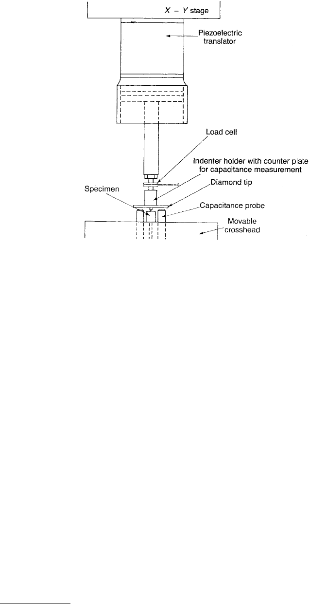
Hannula et al. (1986) developed the nanoindentation apparatus shown in Figure 10.10. It is used to
measure indenter penetration and load as a function of time during loading and unloading cycles. The
apparatus is constructed with two load trains such that both large (up to 50 mm) and small (up to 12 µm)
displacements can be applied accurately and independently to the same specimen. The large displacement
is produced by a moving crosshead. The small displacements are made possible by using a piezoelectric
translator. A load as small as 0.5 mN can be applied.
A specimen is attached to the (moving) crosshead and the diamond tip is attached to a part, which
also serves as a counter plate for two capacitance probes. These probes are used either for controlling
the position of the tip or for measuring the indentation depth. The load cell is placed between the part
and the piezoelectric translator and is used to measure the normal load. The specimen can be aligned
by using an
x
–
y
stage while observing the specimen directly with the microscope.
10.2.2.8 IBM Almaden Research Center Design
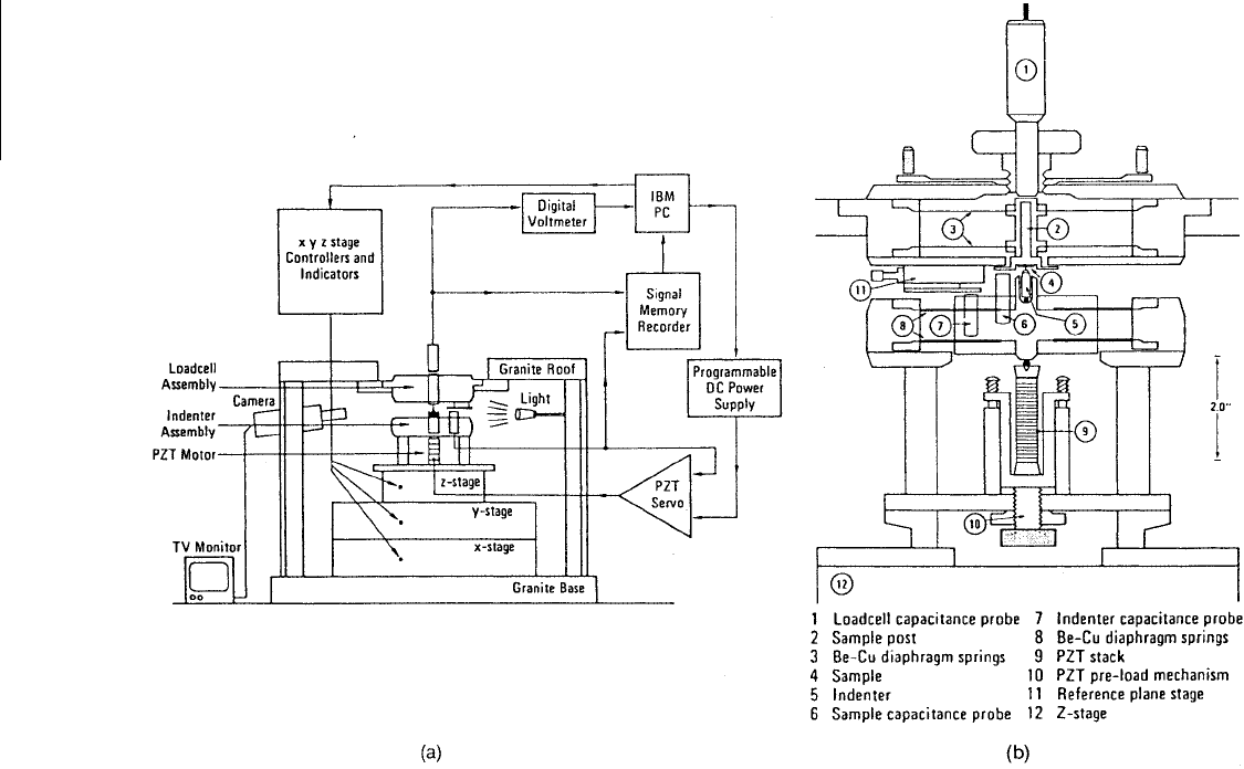
Wu et al. (1988, 1989) built a nanoindentation hardness apparatus based on the Cornell design. Their
apparatus uses a piezoelectric transducer (PZT) for indenter motion, capacitance probe for the displace-
ment, a servo-control circuitry for precise control of PZT motion, a multichannel data acquisition system,
and a closed-loop TV camera for viewing the interface between the indenter tip and sample surface.
(Also see Wu, 1991.) Figure 10.11a shows the block diagram of the apparatus which is composed of an
indenter assembly, a load cell assembly and a fully automated precision
X
–
Y
–
Z
stage. Figure 10.11b shows
schematically the indenter assembly and the load cell assembly. The indenter (5) is driven by a PZT
transducer stack (9) which is monitored by a servo system. The servo mechanism allows great flexibility
FIGURE 10.9
Schematic of a depth-sensing nanoindentation hardness apparatus by Ecole Central of Lyon. (From
Loubet, J.L. et al., 1993, in
Mechanical Properties and Deformation of Materials Having Ultra-Fine Microstructures
(M. Nastasi et al., eds.), pp. 429–447. Kluwer Academic, Dordrecht. With permission.)
© 1999 by CRC Press LLC
in controlling the motion of the indenter. The applied load can be calculated using the output voltage
of the load cell capacitance probe (1) and the calibrated load cell spring constant. The total depth
penetrated by the indenter with respect to the sample surface can be obtained either directly from the
sample capacitance gauge (6) or from the difference of the displacement measurements between indenter
gauge (7) and the load cell gauge (1). The load cell has loading ranges from a few tens of micronewtons
to 2 N with a resolution of about 30 µN. Indentations with a depth of as low as 20 nm with a depth
resolution of 1 nm can be made. For hardness measurements, the apparatus is operated in continuous
loading and unloading modes with indenting speeds of 2 to 20 nm s
–1
. A three-sided pyramidal diamond
indenter, known as the Berkovich indenter, is used for measurements.
The PZT stack is driven by a voltage amplifier to follow a predetermined reference pattern and is
monitored by closed-loop servo-circuitry. Either the indenter displacement (IND) output (7) or the
normal load cell (LC) output (1) can be employed as a servo-input signal and in turn different testing
modes can be generated using an IND servo, constant indenter rate testing (typically used in the constant
loading and unloading tests), or constant indenter position (used in the load relaxation tests), or any
programmed displacement pattern for the indenter can be performed. But using an LC servo, constant
loading rate indentation (used in the continuous loading and unloading tests, or constant load inden-
tation (used in the indentation creep test), or cyclic loading (using sawtooth or sinusoidal references, in
the indentation fatigue tests) can be performed. Furthermore, under the LC servo mode, the microin-
denter can be used as an
in situ
profiler, which is used to measure the scratch track depth. Wu (1993)
modified the nanoindenter for continuous stiffness measurements using dynamic loading based on the
work by Oliver and Pethica (1989) and Pethica and Oliver (1989). The dynamic loading was accomplished
by superimposing a sinusoidal waveform with small amplitude to the linear ramping DC voltage. This
technique will be described in detail in a later section on nanoindenters.
The nanoindenter was modified to perform scratch tests, Figure 10.12a (Wu et al., 1989, 1990b; Wu,
1991). PZT-driven indenter assembly exhibits excellent rigidity and hence is mechanically stable in the
X
–
Y
plane. This extremely rigid design along the horizontal plane is crucial to performing scratch tests.
FIGURE 10.10
Schematic of a depth-sensing nanoindentation hardness apparatus by Cornell University, Ithaca,
NY. (From Hannula, S.P. et al., 1986, in
The Use of Small-Scale Specimens for Testing Irradiated Materials
(W.R. Corwin
and G.E. Lucas, eds.) pp. 233–251, STP 888, ASTM, Philadelphia. With permission.)
© 1999 by CRC Press LLC
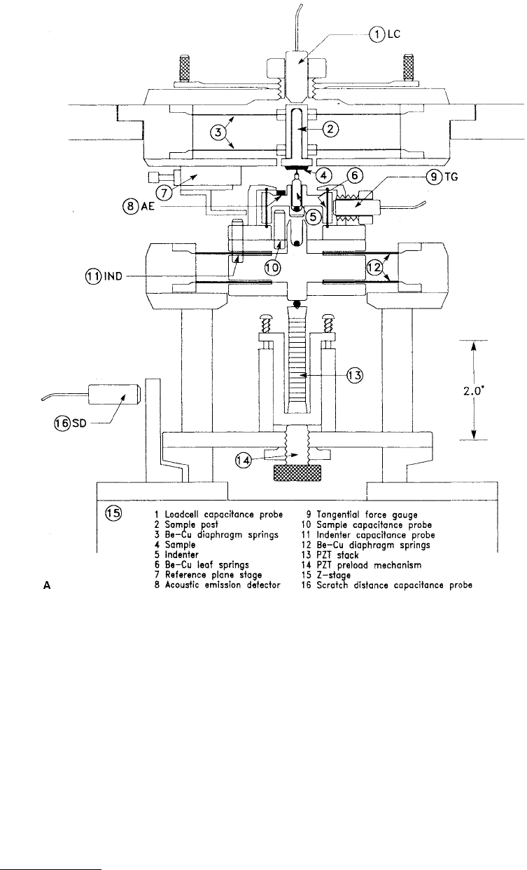
FIGURE 10.11
(a) Block diagram of a depth-sensing nanoindentation hardness apparatus by IBM Almaden Research Center; (b) schematic
diagram of the indenter assembly and normal load cell assembly: (1) load cell capacitance probe, (2) sample post, (3) Be–Cu diaphragm springs;
(4) sample, (5) indenter, (6) sample capacitance probe, (7) indentation capacitance probe, (8) Be–Cu diaphragm, (9) PZT stack, (10) PZT preload
mechanism, (11) reference plane stage, (12) Z-stage. (From Wu, T.W. et al., 1988,
Thin Solid Films
166, 299–308. With permission.)

© 1999 by CRC Press LLC
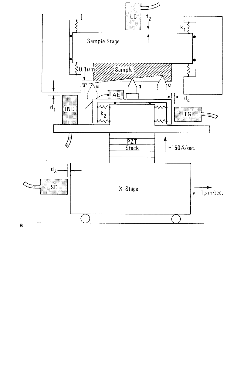
In their modified design, a tangential load cell (6, 9) as well as acoustic emission sensor (8) were added.
An additional capacitance probe (TG, 9) was placed to monitor the displacement of the indenter holder,
which is subsequently used to calculate the tangential force that the indenter applies on the sample
surface. The tangential load cell has a loading range of 750 mN with a resolution of about 15 µN. Another
capacitance probe (SD, 16) was added to measure scratch distance.
Figure 10.12b shows schematically the working principle of a nanoscratch test carried out by the
upgraded apparatus (Figure 10.12a). To perform a scratch test, the indenter is first placed about 0.1 µm
away from the sample surface. This step allows a scratch to begin with a zero applied load. Next the
traveling range and speed of the X-translation stage are set usually at 150 µm and 1 µm/s, respectively;
then the motion is started. Finally, the PZT motor is activated to drive the indenter toward the sample
surface at the speed of about 15 nm/s. With this instrument, the following measurements can be made
simultaneously during a scratch test: applied load and tangential load along the scratch length (coefficient
of friction); critical load, i.e., applied normal load corresponding to an event of coating failure during a
scratch process, total depth and plastic depth along the scratch length; the accumulated acoustic emission
(AE) counts vs. the scratch length. In addition to the mechanical data, scratch morphology analysis is
always available. Examples will be shown later in the chapter.
10.2.3 Commercial Depth-Sensing Nanoindentation Hardness
Apparatus and Its Modifications
10.2.3.1 General Description and Principle of Operation
Although the NEC Corp. design and Micro Materials design presented in the previous section are
commercially available, these are not popular. The most commonly used commercial depth-sensing
nanoindentation hardness apparatus is manufactured by MTS Nano Instruments Innovation Center,
1001 Larson Drive, Oak Ridge, TN 37830. Ongoing development of this apparatus have been described
by Pethica et al. (1983), Oliver et al. (1986), Oliver and Pethica (1989), Pharr and Oliver (1992), and
Oliver and Pharr (1992). This instrument is called the Nanoindenter. The most recent model is Nanoin-
denter II (Anonymous, 1991). The apparatus continuously monitors the load and the position of the
indenter relative to the surface of the specimen (depth of an indent) during the indentation process. The
area of the indent is then calculated from a knowledge of the geometry of the tip of the diamond indenter.
The load resolution is about ±75 nN and position of the indenter can be determined to ±0.1 nm.
Mechanical properties measurements can be made at a minimum penetration depth of about 20 nm (or
a plastic depth of about 15 nm) (Oliver et al., 1986). Specifications for the Nanoindenter are given in
Table 10.1. The description of the instrument that follows is based on Anonymous (1991).
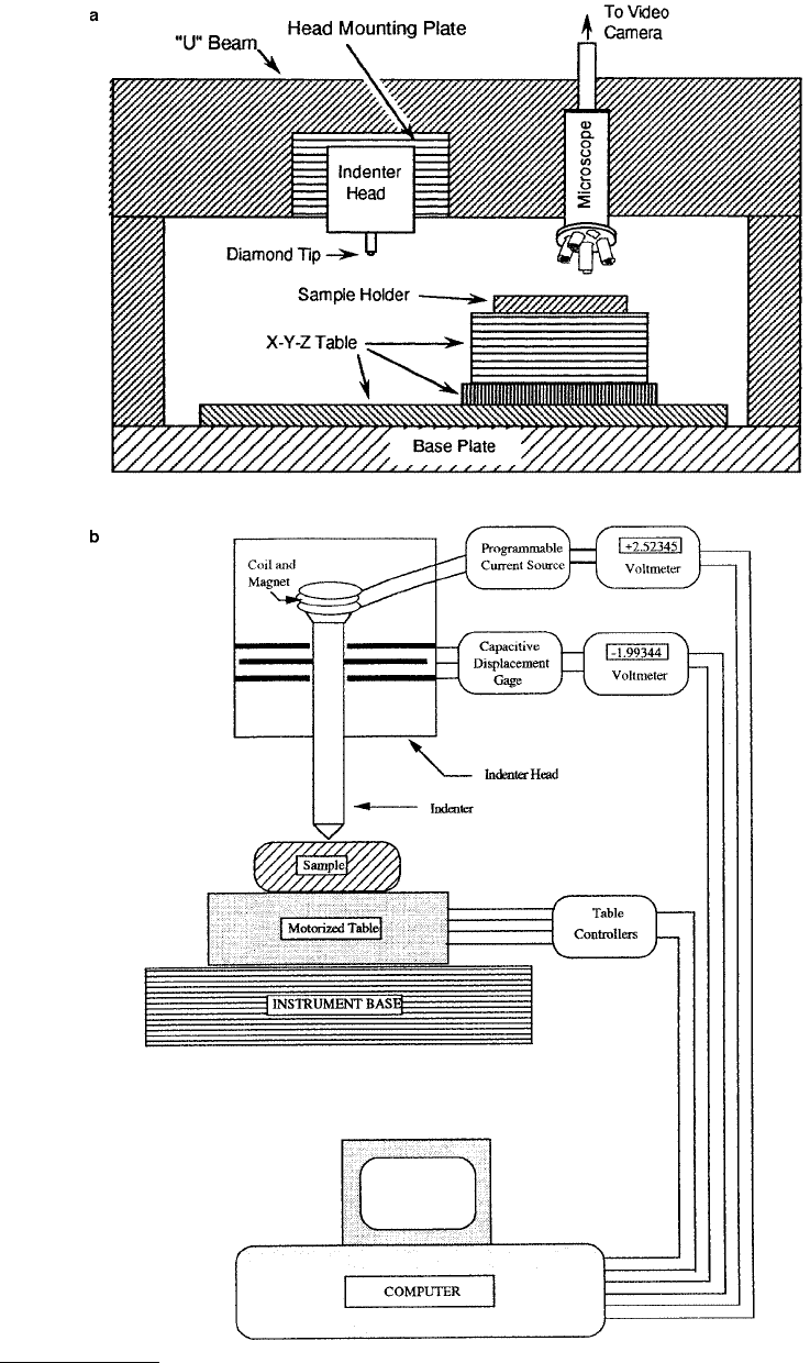
The nanoindenter consists of three major components: the indenter head, an optical microscope, and
an
X
–
Y
–
Z
motorized precision table for positioning and transporting the sample between the optical
microscope and indenter, Figure 10.13a. The loading system used to apply the load to the indenter consists
of a magnet and coil in the indenter head and a high precision current source, Figure 10.13b. A coil is
attached to the top of the indenter (loading) column and is held in a magnetic field. The passage of the
current through the coil is used to raise or lower the column and to apply the required force to make an
indent. The current from the source, after passing through the coil, passes through a precision resistor
across which the voltage is measured and is displayed. During measurement, voltage is controlled by a
computer. Two interchangeable indenter heads are available: the standard head, which features four load
ranges 0 to 4 mN, 0 to 20 mN, 0 to 120 mN, and 0 to 350 mN, and a high-load head, which has a load
range of 0 to 840 mN. The load resolution for the standard head in the most sensitive range is about
±75 nN, while the load resolution for the high load head is ±90 µN.
The displacement-sensing system consists of a special three-plate capacitive displacement sensor, used
to measure the position of the indenter. All three plates are circular disks approximately 1.5 mm thick.
The two outer plates have a diameter of 50 mm, and the inner, moving plate is half that size. The indenter
column is attached to the moving plate. This plate-and-indenter assembly is supported by two leaf springs
cut in such a fashion to have very low stiffness. The motion is damped by airflow around the central
© 1999 by CRC Press LLC
plate of the capacitor, which is attached to the loading column. The load coil is used to raise or lower
the plate and the indenter assembly through its 100-µm travel between the outer plates of the capacitor.
Depth resolution of the systems is about ±0.04 nm. As seen in the plot at the right of Figure 10.13c, a
load voltage of 1.7 V will just lift the indenter off its bottom stop, and 1.8 V suffice to bring it to the top
of its travel. It should be emphasized that only the motion of the indenter column as controlled by the
load coil is used in the actual making of an indent. The voltage output range of the displacement sensing
(capacitance) system is –2.5 to +2.5 V.
At the bottom of the indenter rod, a three-sided pyramidal diamond tip (Berkovich indenter, to be
discussed later) is generally attached.
The indenter head assembly is rigidly attached to the “U” beam below which the
X
–
Y
–
Z
table rides,
Figure 10.13a. The optical microscope is also attached to the beam. The position of an indent on a
specimen is selected using the microscope (maximum magnification of 1500
¥
). The remote-operation
option provides a TV camera that is mounted atop the microscope, which permits the image of the
FIGURE 10.12
© 1999 by CRC Press LLC
specimen to be viewed remotely. The specimens are held on an
X
–
Y
–
Z
table whose position relative to
the microscope or the indenter is controlled with a joystick. The spatial resolution of the position of the
table in the
X
–
Y
plane is ±400 nm and its position is observed on the CRT. The specimen holder is a
rectangular metal plate (150
¥
150
¥
28.5 mm) with ten 31.8-mm-diameter holes for mounting of
standard metallographic samples. Samples can also be glued to special metal disks. The three components
just described are enclosed in a heavy wooden cabinet to ensure the thermal stability of the samples. The
apparatus should be housed in a laboratory in which the temperature is controlled to ±0.5°C. The entire
apparatus is placed on a vibration-isolation table. The operation of the apparatus is completely (IBM-
PC-compatible) computer controlled. Through an IEEE interface, the computer is connected to data
acquisition and control system.
The nanoindenter also comes with a continuous stiffness measurement device (Oliver and Pethica,
1989; Pethica and Oliver, 1989). This device makes possible the continuous measurement of the stiffness
of a sample, which allows the elastic modulus to be calculated as a continuous function of time (or
indentation depth). Useful data can be obtained from indents with depths as small as 20 nm. Because of
FIGURE 10.12
Schematic diagram of the upgraded nanoindentation hardness apparatus with the tangential load
cell assembly: IND, indenter probe; LC, normal load cell probe; TG, tangential load cell probe; SD, scratch distance
probe; and AE, acoustic emission detector, and (b) schematic illustration of the working principle of the nanoscratch
test. From Wu, T.W., 1991,
J. Mater. Res.
6, 407–426. With permission.)

© 1999 by CRC Press LLC
the relatively small time constant of the measurements, the device is particularly useful in studies of time-
dependent properties of materials.
10.2.3.2 Calibration Procedures
Calibration of the loading system involves the accurate measurement of the voltage through the force
coil required to support a series of precalibrated hook weights so as to establish the change in force per
volt. The typical value for this constant is 26,876.5 µN/V.
Calibration of the displacement system is carried out by correlating the voltage output of the displace-
ment capacitor with the number of rings generated as the indenter tip is pressed against a lens-and-plate
system designed to produce newton rings. A mirror mounted at the bottom on the indenter tip is pressed
against a partially reflected lens and an He–Ne laser observed during the test on a video camera. The
relationship between displacement voltage and displacement is linear in the range of interest.
Other important calibrations include microscope-to-indenter distance and spring constant of indenter
support springs.
10.2.3.3 The Berkovich Indenter
The main requirements for the indenter are high elastic modulus, no plastic deformation, low friction,
smooth surface, and a well-defined geometry that is capable of making a well-defined indentation
impression. The first four requirements are satisfied by choosing the diamond material for the tip. A
well-defined perfect tip shape is difficult to achieve. Berkovich is a three-sided pyramid and provides a
sharply pointed tip
compared with the Vickers or Knoop indenters, which are four-sided pyramids and
have a slight offset (0.5 to 1 µm) (Tabor, 1970; Bhushan, 1996). Because any three nonparallel planes
intersect at a single point, it is relatively easy to grind a sharp tip on an indenter if Berkovich geometry
is used. However, an indenter with a sharp tip suffers from a finite but an exceptionally difficult-to-
measure tip bluntness. In addition, pointed indenters produce a virtually constant plastic strain impression
TABLE 10.1
Specification of the Commercial Nanoindenter by Nano Instruments, Inc.
Load range
Standard head 0–4 mN
0–20 mN
0–120 mN
0–350 mN
High load head 0–840 mN
Load resolution
Standard head ±75 nN
High load head ±90 nN
Vertical displacement range 0–100 µm
Vertical displacement resolution ±0.1 nm
Typical approach rate 10 nm/s
Typical indentation load rate 10% of peak load/s
Typical indentation displacement rate 10% peak diplacement/s
Optical microscope magnification up to 1500
¥
Spatial resolution of the
X
–
Y
–
Z
table ±400 nm in the
X
- and
Y
-directions
Area examined in a single series of indentations 150
¥
150 mm
Minimum penetration depth ~20 nm
Continuous stiffness option
Frequency range 10–150 Hz
Time constant 0.33 s
Smallest measurable distance 0.1 nm
Scratch and tangential force option
Scratch velocity max. 100 µm/s with 20 points/mm
Tangential displacement range 2 mm
Tangential displacement resolution 400 nm
Tangential load resolution 50 µN
Minimum measurable tangential load 0.5 mN

© 1999 by CRC Press LLC
and there is the additional problem of assessing the elastic modulus from the continuously varying
unloading slope. Spherical indentation overcomes many of the problems associated with pointed indent-
ers. With a spherical indenter, one is able to follow the transition from elastic to plastic behavior and
thereby define the yield stress (Bell et al., 1992). However, a sharper tip is desirable, especially for extremely
thin films requiring shallow indentation. Therefore, Berkovich indenter is most commonly used for
measurements of nanomechanical properties. Experimental procedures have been developed to correct
for the tip shape, to be described later.
In the construction of the Berkovich indenter, an octahedron piece of diamond with large dimension
of
½
¥
½
¥
½
mm, is directly brazed to a 304 stainless steel holder and the tip is ground to Berkovich
shape. The Berkovich indenter is a three-sided (triangular-based) pyramidal diamond, with a nominal
angle of 65.3° between the (side) face and the normal to the base at apex, an angle of 76.9° between edge
and normal, and with a radius of the tip less than 0.1 µm (Figure 10.14a and b) (Berkovich, 1951). The
typical indenter is shaped to be used for indentation (penetration) depths of 10 to 20 µm. The indents
appear as equilateral triangles (Figure 10.14c) and the height of triangular indent l
is related to the depth
h
as
(10.1a)
The relationship
h
(l
) is dependent on the shape of the indenter. The height of the triangular indent l
is
related to the length of one side of the triangle
a
as
(10.1b)
and
(10.1c)
The projected contact area (
A) for the assumed geometry is given as
(10.2)
The exact shape of the indenter tip needs to be measured for determination of hardness and Young’s
modulus of elasticity. Since the indenter is quite blunt, direct imaging of indentations of small size in
the SEM is difficult. Determination of tip area function will be discussed later.
10.2.3.4 Indentation Procedure
The indenter procedure in this section is based on Anonymous (1991). An indentation test involves
moving the indenter to the surface of the material and measuring the forces and displacements associated
during indentation. The surface is located for each indentation by lowering the indenter at a constant
loading rate against the suspending springs and detecting a change in velocity on contact with the surface.
In the testing mode, the load is incremented in order to maintain a constant loading rate or constant
displacement rate. The load and indentation depths are measured during indentation both in the loading
and unloading cycles. The force contribution of the suspending springs and the displacements associated
with the measured compliance of the instrument are removed.
Prior to indentation of test region on the sample surface, the scheme for the indentation pattern is
selected. Typical indentation experiment consists of combination of several segments e.g., approach, load,
hold, and unload, which can be programmed, Figure 10.15. Two typical examples are shown in Table 10.2
(Oliver and Pharr, 1992). A maximum of 12 segments can be programmed for an experiment. After
h
l
=
=
1
2
76 9
1
859
cot .
.
l = 0 866. a
h
a
=
1
7 407.
Aa h==0 433 23 76
22
..
© 1999 by CRC Press LLC