Coker A.K. Fortran Programs for Chemical Process Design, Analysis, and Simulation
Подождите немного. Документ загружается.

Instrument Sizing 347
f~ = mass fraction in the liquid phase
F k = ratio of specific heats factor (k/1.40)
k - ratio of specific heats (Cp/C v)
K = superheat correction factor
K D = coefficient of discharge
P~ = inlet pressure, psia
P2 =
outlet pressure, psia
AP = pressure drop, psi
q = fluid flow rate
QI = liquid flow rate, gpm
Qg
-
gas flow rate,ft3/h at 14.7 psia and 60~
SpGrf = specific gravity of fluid
SpGr~ = specific gravity of liquid
SpGrg -specific gravity of gas - M Wt of gas/M Wt of air
T = flowing temperature, ~ (~ + 460)
V e = effective specific volume of the stream
Vg- specific volume of the inlet gas
V~ = specific volume of the inlet liquid
X T - pressure drop ratio factor (from manufacturer)
W = steam flow, lb/h
RELIEF VALVE SIZING
Introduction
Safety relief valves serve a valuable function in protecting against
overpressure of pipework and process equipment. This may occur due
to operational malfunction, such as equipment failure, fire or human
error. Proper sizing of a relief system is therefore essential. This requires
the determination of proper relieving conditions (e.g., flows, pressures
,and temperatures) so that relief valves and their associated pipework
can be properly sized for the worst scenario. Designers are responsible
to obviate all conceivable conditions, and good judgment must be
exercized in setting the relief requirements (set pressure, for example)
in all design facets during hazard and operability studies. Here, five
relief conditions are considered [ 11 ]:
9 gas or vapor
9 steam
9 liquid
348
Fortran Programs for Chemical Process Design
9 air
9 fire
In addition, noise suppression, preferred location of relief valves, and
pressure drop requirements for stable operation involving inlet pipe to
the valve and tail pipe are reviewed.
Typical Relief Valves
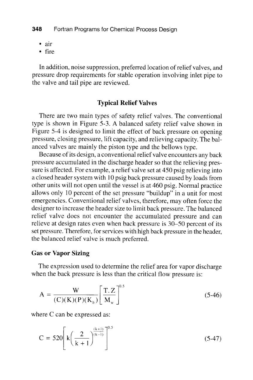
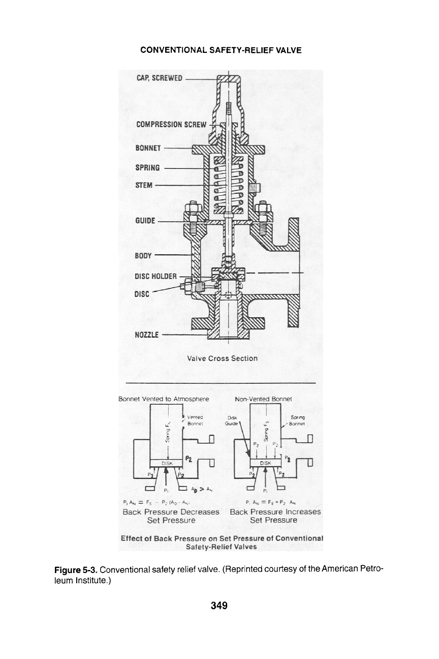
There are two main types of safety relief valves. The conventional
type is shown in Figure 5-3. A balanced safety relief valve shown in
Figure 5-4 is designed to limit the effect of back pressure on opening
pressure, closing pressure, lift capacity, and relieving capacity. The bal-
anced valves are mainly the piston type and the bellows type.
Because of its design, a conventional relief valve encounters any back
pressure accumulated in the discharge header so that the relieving pres-
sure is affected. For example, a relief valve set at 450 psig relieving into
a closed header system with 10 psig back pressure caused by loads from
other units will not open until the vessel is at 460 psig. Normal practice
allows only 10 percent of the set pressure "buildup" in a unit for most
emergencies. Conventional relief valves, therefore, may often force the
designer to increase the header size to limit back pressure. The balanced
relief valve does not encounter the accumulated pressure and can
relieve at design rates even when back pressure is 30-50 percent of its
set pressure. Therefore, for services with high back pressure in the header,
the balanced relief valve is much preferred.
Gas or Vapor Sizing
The expression used to determine the relief area for vapor discharge
when the back pressure is less than the critical flow pressure is:
I
A- W T.
(C)(K)(P)(K b ) M (5-46)
where C can be expressed as:
I ( / (k+l) 10.5
C-520 k 2
k+l
(5-47)
CONVENTIONAL SAFETY-RELIEF VALVE
Figure 5-3. Conventional safety relief valve. (Reprinted courtesy of the American Petro-
leum Institute.)
349
BALANCED SAFETY-RELIEF VALVE
Figure 5-4. Balanced safety-relief valve. (Reprinted courtesy of the American Petro-
leum Institute.)
350
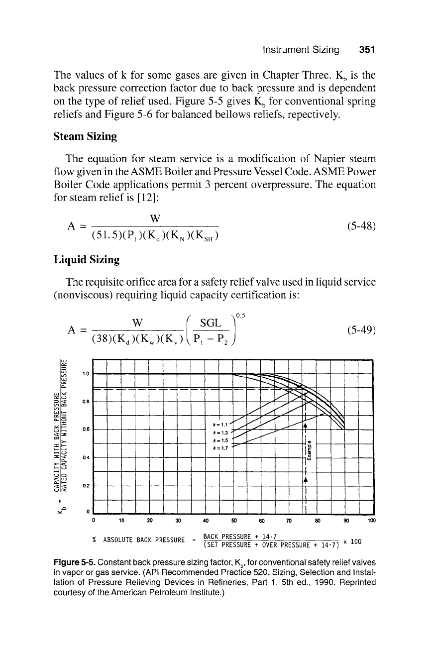
Instrument Sizing 351
The values of k for some gases are given in Chapter Three.
K b
is the
back pressure correction factor due to back pressure and is dependent
on the type of relief used. Figure 5-5 gives
K b
for conventional spring
reliefs and Figure 5-6 for balanced bellows reliefs, repectively.
Steam Sizing
The equation for steam service is a modification of Napier steam
flow given in the ASME Boiler and Pressure Vessel Code. ASME Power
Boiler Code applications permit 3 percent overpressure. The equation
for steam relief is [ 12]:
A
-
W (5-48)
(51.5)(P, )(K d )(K N )(Ks. )
Liquid Sizing
The requisite orifice area for a safety relief valve used in liquid service
(nonviscous) requiring liquid capacity certification is"
)0.5
A - W SGL (5-49)
(38)(K a)(K w)(K~) PI - P2
ILl
(./3
I.IJ
I---
3=
I---
e~
II
e~
0 ,,
0 10 20 30 40 90 100
I
-
k:1.5
.~. ~, ~ ~._e
i""
I
!
I
I
!
50 60 70 80
% ABSOLUTE BACK PRESSURE =
BACK PRESSURE + 14.7
(SET PRESSURE + OVER PRESSURE + 14"7) x 100
Figure 5-5. Constant back pressure sizing factor, K b, for conventional safety relief valves
in vapor or gas service. (API Recommended Practice 520, Sizing, Selection and Instal-
lation of Pressure Relieving Devices in Refineries, Part 1, 5th ed., 1990. Reprinted
courtesy of the American Petroleum Institute.)
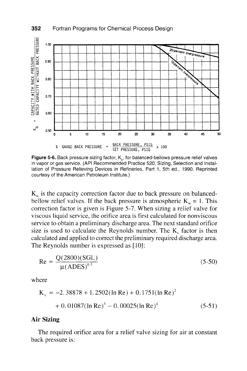
352 Fortran Programs for Chemical Process Design
LIJ
r
IX.
",t
CC3
"1"
p-
I-"
II
0.50
0 5
10 15 2O 25
' ~
Oercent
~reSSure
' r
N
\
30 35 40 45
50
% GAUGE BACK PRESSURE =
BACK PRESSURE, PSIG
SET PRESSURE, PSIG
x 100
Figure 5-6. Back pressure sizing factor, K b, for balanced-bellows pressure relief valves
in vapor or gas service. (API Recommended Practice 520, Sizing, Selection and Instal-
lation of Pressure Relieving Devices in Refineries, Part 1, 5th ed., 1990. Reprinted
courtesy of the American Petroleum Institute.)
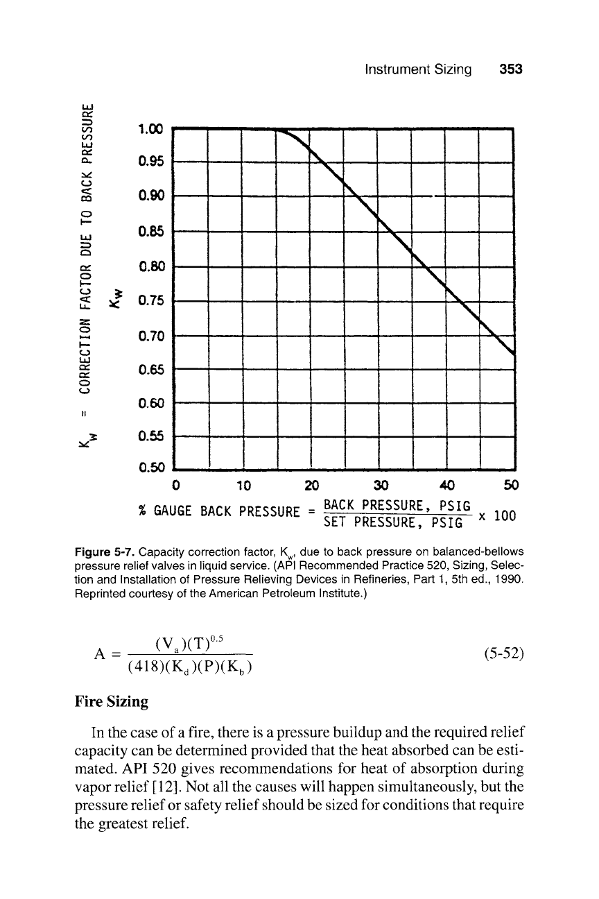
K w is the capacity correction factor due to back pressure on balanced-
bellow relief valves. If the back pressure is atmospheric K w = 1. This
correction factor is given is Figure 5-7. When sizing a relief valve for
viscous liquid service, the orifice area is first calculated for nonviscous
service to obtain a preliminary discharge area. The next standard orifice
size is used to calculate the Reynolds number. The K v factor is then
calculated and applied to correct the preliminary required discharge area.
The Reynolds number is expressed as [10]:
Re - Q(2800)(SGL) (5-50)
g(ADES) ~
where
K v - -2.38878 + 1.2502(ln Re) + 0.1751(ln Re) 2
+ 0.01087 (ln Re)3 _ 0.00025 (ln Re)4
(5-51)
Air Sizing
The required orifice area for a relief valve sizing for air at constant
back pressure is"
Instrument Sizing 353
w
ILl
I--
I.a.I
I--
I.a.
Q
I.--
l.a.I
Q
1.00
0.95
0.90
0.85
~. ,1,,,
\\
= =
9 ~ 1 ..... ! , - -
,. L t., \,,,.
X
0.70
0.65
0.60
3=
0.55 ----------------
' '
0.50
0 10 2O 3O 40 5O
% GAUGE BACK PRESSURE = BACK PRESSURE, PSIG
SET PRESSURE, PSIG
x 100
Figure 5-7. Capacity correction factor, K w, due to back pressure on balanced-bellows
pressure relief valves in liquid service. (API Recommended Practice 520, Sizing, Selec-
tion and Installation of Pressure Relieving Devices in Refineries, Part 1, 5th
ed., 1990.
Reprinted courtesy of the American Petroleum Institute.)
A (V)(T) ~
-
~ (5-52)
(418)(K d)(P)(K b)
Fire Sizing
In the case of a fire, there is a pressure buildup and the required relief
capacity can be determined provided that the heat absorbed can be esti-
mated. API 520 gives recommendations for heat of absorption during
vapor relief [ 12]. Not all the causes will happen simultaneously, but the
pressure relief or safety relief should be sized for conditions that require
the greatest relief.
354 Fortran Programs for Chemical Process Design
Inconsistencies for sizing relief valves for fire emergencies arise
among published codes. This is because of varying interpretations of
the heat flux caused by fire exposure. These variations are based on the
area in which the heat flux applies and the protection factors used to
characterize the installations. Crozier [13] has summarized these varia-
tions and evaluated the pertinent correlations. Here, the API 520 corre-
lation is used because it contains an implied protection factor of 0.5 for
good drainage.
Liquid in liquid-filled vessels exposed to direct or radiated heat from
a fire will vaporize. The heat required to accomplish this will limit the
shell temperature of the tank to only a slight rise. The amount of liquid
vaporized depends on the rate of heat input from the fire and the reliev-
ing temperature. This can be determined by calculating the heat input to
the wetted surface of the vessel and dividing this by the latent heat
of vaporization.
Qr -- 21,000(FI)(Aw)
~
(5-53)
and
W = Qr (5-54)
The vapor to be relieved is the vapor in equilibrium with the liquid (that
is, saturated vapor at the conditions existing when the valve is relieving
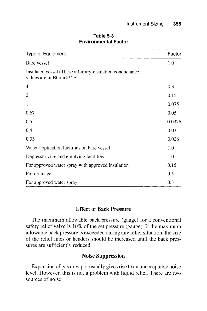
at the rated capacity). Table 5-3 shows environmental factors for bare
and insulated vessels.
For a multicomponent mixture, )~m~ can be determined from
~. ~iYiMi
~' mix -
M (5-55)
i--I
To determine y~, it is necessary to know the equilibrium liquid-phase
mole fraction, x~, at the bubble point corresponding to the accumulated
relieving pressure.
The wetted surface area depends on the diameter and length of the
vessel. For working storage tanks, the wetted surface is obtained on the
average inventory. Surge drums usually operate about half full; thus the
wetted surface will be calculated at 50 percent of the total vessel surface.
Instrument Sizing
355
Table 5-3
Environmental Factor
Type of Equipment
Factor
Bare vessel
1.0
Insulated vessel (These arbitrary insulation conductance
values are in Btu/hrft 2 ~
0.3
0.15
0.075
0.67
0.05
0.5
0.4
0.0376
0.03
0.33
0.026
Water-application facilities on bare vessel
Depressurizing and emptying facilities
For approved water spray with approved insulation
For drainage
For approved water spray
1.0
1.0
0.15
0.5
0.3
Effect of Back Pressure
The maximum allowable back pressure (gauge) for a conventional
safety relief valve is 10% of the set pressure (gauge). If the maximum
allowable back pressure is exceeded during any relief situation, the size
of the relief lines or headers should be increased until the back pres-
sures are sufficiently reduced.
Noise Suppression
Expansion of gas or vapor usually gives rise to an unacceptable noise
level. However, this is not a problem with liquid relief. There are two
sources of noise:
356
Fortran Programs for Chemical Process Design
1. Noise due to turbulence at the point where the gas mixes with the
atmosphere. Suppression of this type of noise involves the fitting
of a silencer.
2. Noise due to pressure letdown (that is, relief valve) when sonic or
near sonic velocities are generated. This is transmitted through
the wall of pipe and, if the discharge is short, it is transmitted
through the open end. Noise from this can be reduced by length-
ening the discharged pipe and by insulation. Suppression of the
noise can also be overcome by fitting a silencer. Such silencers are
often installed in an exposed environment and are likely to accumu-
late dirt, vapor, or products from minor leakage of safety devices.
Effect of Pressure
Drop (AP) on
Pipework
The pipework should be designed with the following considerations:
9 The frictional AP through the inlet pipework, inlet fittings, and
valves at the maximum possible relief rate should not exceed 3%
of the set gauge pressure (psig). The calculation of AP should
include the entrance loss of the inlet pipework. The discharge
pipework must be such that AP is less than 10% of the relieving
pressure (that is, set pressure plus overpressure in gauge). The dis-
charge pipework should withstand the internal pressure and high
velocities, the reaction forces, and the sudden transient loading that
occur when a relief device suddenly comes into operation.
9 The inlet pipework should be of a size at least equal to the relief
valve, with its length minimized to reduce AP. It should also be
equal to the bending moments resulting from the forces that
develop when the valve or disc is discharging at full capacity.
9 A relief device should be installed vertically and preferably on a
nozzle at the top of the equipment (for example, vessel) or on a tee
connected to a pipeline. When discharging a gas or vapor, the fluid
reaches sonic velocity when passing through a relief device. Thus,
the gas flow rate or AP can be determined by a method as described
in Chapter Three.
For liquid discharges, the design of the pipework may be complex. If
the liquid is subcooled, the discharge pipework is sized by standard
liquid pressure formulae. If the liquid in the equipment is at or near its
saturation pressure, the relief device and discharge pipework should be
sized for two-phase flow. As the liquid flows through the relief valve,