Dinc Ibrahim. Refrigeration systems and applications 2th edition
Подождите немного. Документ загружается.


Refrigeration Cycles and Systems 191
in sizes from 10 to 1000 tons, leading to the lowest evaporation temperature of 4
◦
C (with a mini-
mum pressure of 0.8 kPa) because the water is used as the refrigerant. In practical applications, the
temperature is 5
◦
C. Low-pressure steam is the main energy source for these H
2
O–LiBr absorption
systems. Despite their COPs less than unity, cheap energy can make these systems economically
competitive with much higher COP values for vapor-compression systems. In practical H
2
O–LiBr
ARSs, the evaporator and absorber are combined in a shell at the lower-pressure side and the con-
denser and generator are combined in another shell at the higher-pressure level. A liquid–liquid heat
exchanger is arranged to increase system efficiency and hence to improve the COP. Its operating
principle is the same as that of other ARSs. In the H
2
O–LiBr ARS, crystallization (which is a
solidification of the LiBr) appears to be a significant problem. The crystallization lines are shown
on the pressure–temperature and enthalpy–concentration charts. Dropping into the crystallization
region causes the formation of slush, resulting in blockage of the flow inside the pipe and interrup-
tion of the system operation. In order to prevent this problem, practical systems are designed with
control devices to keep the condensation pressure artificially high. Note that absorption chillers
and/or refrigeration systems are classified into three categories as follows:
• Single-effect ARS. Units using low pressure (135 kPa or less) as the driving force. These units
typically have a COP of 0.7.
• Double-effect ARS. Units are available as gas-fired (either direct gas firing, or hot exhaust gas
from a gas-turbine or engine) or steam-driven with high-pressure steam (270 to 950 kPa). These
units typically have a COP of 1.0 to 1.2. To achieve this improved performance they have a
second generator in the cycle and require a higher temperature energy source.
• Triple-effect ARS. Although the units are not fully available for commercial applications, the
concept is well-developed and experiments are conducted for applications through various patents
(e.g., Patent Storm, 2010) and some papers (e.g., Kaita, 2001). This triple-effect ARS can use
any heat source from waste heat to renewable energy sources, including solar and geothermal
heat. The pressure of steam further increases here due to the additional effect (stage) and may
easily go beyond the double-effect ARS pressures. The COPs of these three-effect units may
become 13 and higher for ammonia-water ARSs, and 1.6 and higher for water-LiBr ARSs. Such
COPs are really encouraging for practical applications. The operation of this kind of triple-effect
ARS may be described briefly as follows:
An absorber provides strong solution to three generators, including a high-temperature generator,
an intermediate-temperature generator, and a low-temperature generators in which all may be
connected in parallel or inverse series. Each generator feeds refrigerant vapor to a corresponding
condenser, including a high-temperature condenser, an intermediate-temperature condenser, and
a low-temperature condenser. The higher-temperature condensers are essentially coupled with
the lower temperature generators, respectively. Hence, the system is referred to as a double-
coupled condenser triple effect absorption system. The three heat exchangers may be provided
in the parallel or inverse series flowpath from the absorber. It is possible to configure this
system differently which requires further research and development to find the best option for
applications.
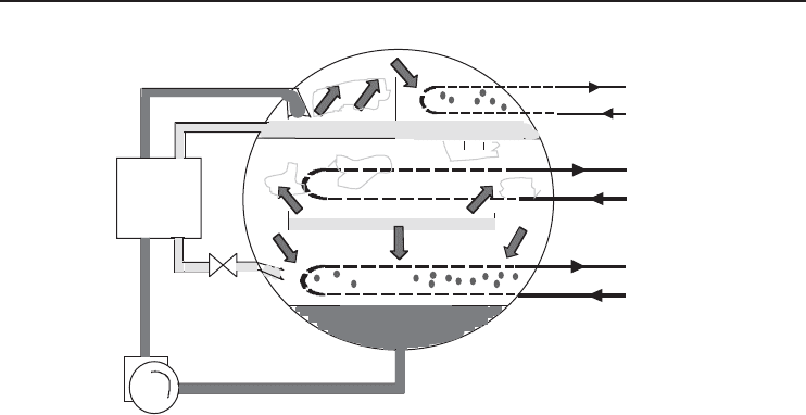
4.7.5.1 Single-Effect ARS
As stated earlier, in ARS, an absorber, generator, pump, and recuperative heat exchanger replace
the compressor. Like mechanical refrigeration, as shown in Figure 4.25, the cycle begins when
high-pressure liquid refrigerant from the condenser passes through a metering device (1) into the
lower-pressure evaporator (2) and collects in the evaporator pan or sump. As before, the flashing that
occurs at the entrance to the evaporator cools the remaining liquid refrigerant. Similarly, the transfer
of heat from the comparatively warm system water to the now-cool refrigerant causes the latter
to evaporate (2), and the resulting refrigerant vapor migrates to the lower-pressure absorber (3).
192 Refrigeration Systems and Applications
Heat
exchanger
Absorb
Evaporate
Expand
Generate
Condense
Cooling
water
Cooling
water
Chilled
water
1
2
3
4
5
6
Figure 4.25 Schematic of a single-effect ARS.
There, it is soaked up by an absorbent lithium bromide solution. This process not only creates a low-
pressure area that draws a continuous flow of refrigerant vapor from the evaporator to the absorber,
but also causes the vapor to condense (3) as it releases the heat of vaporization picked up in the evap-
orator. This heat – along with the heat of dilution produced as the refrigerant condensate mixes with
the absorbent – is transferred to the cooling water and is released in the cooling tower. Of course,
assimilating refrigerant dilutes the lithium bromide solution and reduces its affinity for refrigerant
vapor. To sustain the refrigeration cycle, the solution must be reconcentrated. This is accomplished
by constantly pumping (4) dilute solution from the absorber to the generator (5), where the addition
of heat boils the refrigerant from the absorbent. Once the refrigerant is removed, the reconcentrated
lithium bromide solution returns to the absorber, ready to resume the absorption process. Mean-
while, the refrigerant vapor liberated in the generator migrates to the cooler condenser (6). There,
the refrigerant returns to its liquid state as the cooling water picks up the heat of vaporization
carried by the vapor. The liquid refrigerant’s return to the metering device (1) completes the cycle.
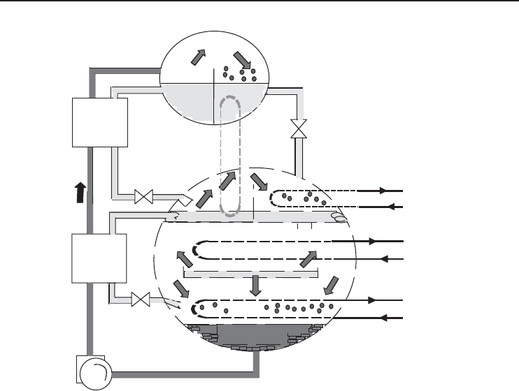
4.7.5.2 Double-Effect ARS
The energy efficiency of absorption can be improved by recovering some of the heat normally
rejected to the cooling tower circuit. A two-stage or two-effect ARS accomplishes this by taking
vapors driven off by heating the first-stage concentrator (or generator) to drive off more water in a
second stage. Many ARS manufacturers offer this higher efficiency alternative.
The double-effect ARS takes absorption to the next level. The easiest way to picture a double-
effect cycle is to think of two single-effect cycles stacked on top of each other (as shown in
Figure 4.26). Note that two separate shells are used. The smaller is the first-stage concentrator.
The second shell is essentially the single-effect ARS from before, containing the concentrator,
condenser, evaporator, and ARS. The temperatures, pressures, and solution concentrations within
the larger shell are similar to the single-effect ARS as well. The cycle on top is driven either directly
by a natural gas or oil burner, or indirectly by steam. Heat is added to the generator of the topping
cycle (primary generator), which generates refrigerant vapor at a relatively higher temperature and
pressure. The vapor is then condensed at this higher temperature and pressure and the heat of
condensation is used to drive the generator of the bottoming cycle (secondary generator), which is
at a lower temperature. If the heat added to the generator is thought to be equivalent to the heat of
condensation of the refrigerant, it becomes clear where the efficiency improvement comes from.
Refrigeration Cycles and Systems 193
Heat
exchanger
Absorb
Evaporate
Expand
Generate
Condense
Cooling
water
Cooling
water
Chilled
water
4
6
Heat
exchanger
Generate
Condense
7
8
Figure 4.26 Schematic of a double-effect ARS.
For every unit of heat into the primary generator, two masses of refrigerant are boiled out of
solution, or generated: one in the primary generator and one in the secondary generator. In a single-
effect cycle only one mass is generated. Therefore, in a double-effect system, twice the mass flow of
refrigerant is sent through the refrigerant loop per unit of heat input, so twice the cooling is delivered
per unit of heat input. Using this approach a double-effect system has a COP that is roughly twice
that of a single-effect cycle. However, this simplifying assumption does not account for cycle
inefficiencies and losses. In actuality, a single-effect system has a COP of about 0.65 and a double-
effect system has a COP of about 1.0. Note that the reuse of the vapors from the first-stage generator
makes this machine more efficient than single-stage absorption chillers, typically by about 30%.
4.7.5.3 Crystallization
Some absorption chillers are notorious for “freezing up” or crystallizing. The basic mechanism of
failure is simple enough – the lithium bromide solution becomes so concentrated that crystals of
lithium bromide form and plug the machine (usually the heat exchanger section). The most frequent
causes are as follows:
• air leakage into the machine,
• low-temperature condenser water, and
• electric power failures.
The first two are actually very similar since they both drive the heat input up to the point that
crystallization can occur. Whether air leaks into the machine or the condenser water temperature is

194 Refrigeration Systems and Applications
too low, the water vapor pressure in the absorption chiller evaporator has to be lower than normal
to produce the required cooling. This forces the heat input to the machine to be higher to increase
the solution concentration. Air leakage into the machine can be controlled by designing the machine
with hermetic integrity and routinely purging the unit using a vacuum pump.
Excessively cold condenser water (coupled with a high load condition) can also cause crystalliza-
tion. While reducing condenser water temperature does improve performance, it could cause a low
enough temperature in the heat exchanger to crystallize the concentrate. Sudden drops in condenser
water temperature could cause crystallization. For this reason, some of the early absorption chillers
were designed to produce a constant condenser water temperature. Modern absorption chillers have
special controls that limit the heat input to the machine during these periods of lower condenser
water temperatures.
Power failures can cause crystallization as well. A normal absorption chiller shutdown uses a
dilution cycle that lowers the concentration throughout the machine. At this reduced concentration,
the machine may cool to ambient temperature without crystallization. However, if power is lost
when the machine is under full load and highly concentrated solution is passing through the heat
exchanger, crystallization can occur. The longer the power is out, the greater the probability of
crystallization.
Major absorption chiller manufacturers now incorporate devices that minimize the possibility
of crystallization. These devices sense impending crystallization and shut the machine down after
going through a dilution cycle. These devices also prevent crystallization in the event of power
failure. A typical anti-crystallization device consists of two primary components: (i) a sensor in
the concentrated solution line at a point between the concentrator and the heat exchanger and
(ii) a normally open, two-position valve located in a line connecting the concentrated solution line
and the line supplying refrigerant to the evaporator sprays.
4.7.6 The Steam Ejector Recompression ARS
The ejector recompression absorption cycle, which was developed by Eames and Wu (2000), is
similar to the conventional single-effect lithium bromide absorption cycle. The difference between
them is that there is a steam ejector in this novel cycle for enhancing the concentration process.
Because of the use of the steam ejector, the performance and the operating characteristics of the
novel cycle are different from the conventional cycle.
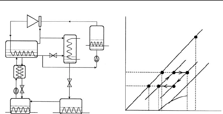
The steam ejector recompression absorption cycle is shown schematically in Figure 4.27a. In
this figure, the expansion of the high-pressure steam causes a low pressure at the exit of the
primary nozzle of the steam ejector; therefore, the vapor at point 8 in the concentrator is entrained
by the primary flow. The two streams are mixed in the steam ejector and condensed in the heat
exchanger of the concentrator. The condensation heat is used to heat the solution in the concentrator.
Obviously, the heat of the entrained vapor is recovered by the steam ejector in this process. Water
at point 3 splits into two streams; one flows back to the steam generator and the other flows into
the condenser. In stable operation, the mass flow rate of the first stream equals that of primary
flow, while the mass flow rate of the second stream equals that of the entrained vapor. The rest
of the cycle is similar to that of the conventional single-effect lithium bromide absorption cycle.
Figure 4.27b shows the novel cycle on a P–T–C diagram. As shown in Figure 4.27b, the cycle
6–7–9–10–6 takes up water at the absorber (10−6) and releases it as vapor at the concentrator
(7–9). In the conventional absorption cycle, the vapor is condensed at 8
and the condensation heat
is rejected to the surroundings. In the novel cycle, this vapor undergoes a compression process
through the ejector to point 2. Since the vapor temperature is greater than the solution temperature
in the concentrator, this vapor is used to heat the solution by condensation to point 3. Therefore
the heat otherwise wasted is recovered and the energy efficiency is improved.
Eames and Wu (2000) investigated the energy efficiency and the performance characteristics of
the novel cycle and the theoretical results showed that the COP of the novel cycle is better than
Refrigeration Cycles and Systems 195
(
b
)(
a
)
Concentrated
Dilute
0 %
2,3
10
8,9
7
8′
6
5
TT
con
T
3
T
g
T
a
T
c
P
c
P
g
P
Water
pump
4
6
5
Evaporator
Absorber
Restrictor
Restrictor
Restrictor
Solution
pump
Solution heat
exchanger
10
97
3
8
Condenser
Concentrator
·
m
1
·
m
8,T
·
m
8
·
m
2
Steam generator
1
2
Ejector
Figure 4.27 (a) The steam ejector recompression ARS and (b) its P –T –C diagram (Eames and Wu, 2000)
(Reprinted with permission from Elsevier Science).
that of the conventional single-effect absorption cycle. The characteristics of the cycle performance
show its promise in using high-temperature heat source at low cost.
In the past, Kang et al. (2000) undertook a study to propose and evaluate advanced
absorption cycles for the COP improvement and temperature lift enhancement applications. The
characteristics of each cycle are assessed from the viewpoints of the ideal cycle COP and its
applications. The advanced cycles for the COP improvement are categorized according to their
heat recovery method: condensation heat recovery, absorption heat recovery, and condensation/
absorption heat recovery. In H
2
O–LiBr systems, the number of effects and the number of stages
can be improved by adding a third or a fourth component to the solution pairs. The performance
of NH
3
–H
2
O systems can be improved by internal heat recovery because of their thermal
characteristics such as temperature gliding. NH
3
–H
2
O cycles can be combined with adsorption
cycles and power generation cycles for waste heat utilization, performance improvement, panel
heating, and low-temperature applications. The H
2
O–LiBr cycle is better from the high COP
viewpoint for evaporation temperature over 0
◦
C while the NH
3
–H
2
O cycle is better from the
viewpoint of low-temperature applications. This study suggests that the cycle performance would
be significantly improved by combining the advanced H
2
O–LiBr and NH
3
–H
2
Ocycles.
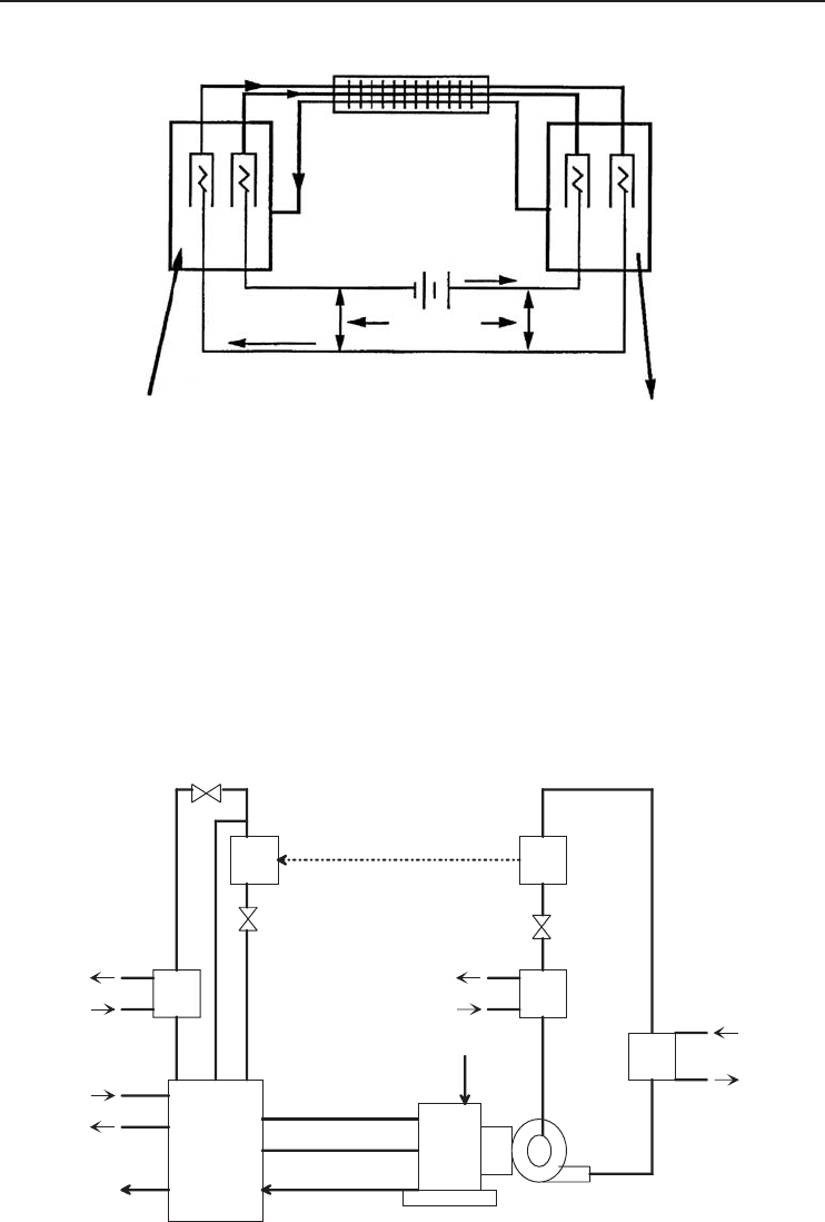
4.7.7 The Electrochemical ARS
In another study, Newell (2000) proposed a new electrochemical ARS as shown in Figure 4.28,
which consists of four main components. An electrochemical cell is the heat absorber, equivalent
to an evaporator in a conventional vapor-compression refrigeration system. A fuel cell rejects heat
in a manner similar to a condenser in a common vapor-compression refrigeration cycle. The third
component is a heat exchanger between gas streams and water flow stream. The fourth component
is a current pump for elevating the fuel cell’s voltage output to a level sufficient for driving the
electrochemical cell. The voltage required is sufficiently low such that the cycle may be one that is
conveniently matched for solar photovoltaic cells or other direct current electric energy conversion
systems. In fact, the system shown in Figure 4.28 can be used as a thermally driven power cycle
by operating the fuel cell at a temperature lower than the electrochemical cell. The voltage supply
196 Refrigeration Systems and Applications
Heat exchanger
H
2
O2
H
2
O
Electrochemical
cell
Fuel
cell
Current flow
Current flow
Heat and
work IN
Heat and
work OU
T
∆ V electrochemical
cell
∆ V fuel cell
∆ V added
Figure 4.28 Schematic representation of the electrochemical ARS (Newell, 2000).
becomes a load driven by the electric circuit. Lowering component irreversibilities is essential
to reach a breakeven operating condition where the fuel cell is generating sufficient power for
operation of the electrochemical cell. Newell’s system is based on a water/hydrogen/oxygen fuel
cell and electrochemical cell combination. Other combinations are also considered. Each one has its
own advantages or disadvantages. The configuration envisioned for the system operates near atmo-
spheric pressure. The components could be operated at nearly uniform pressures with gravitation,
surface tension, or low head pumping used for transporting the working fluids within and between
components. Water may be moved from the electrochemical cell and fuel cell to external heat
exchange surfaces, or the cells could be configured for direct heat exchange with their surroundings.
Engine
Absorption
system
Compressor
Engine coolant
Exhaust
Cooling water
Exhaust
Brine
LP evaporator
Precooler
LP evaporator
Evaporator
Brine
Fuel
Condenser
Condense
r
coolant
Figure 4.29 Absorption-augmented engine-driven refrigeration system (Turpin, 2000).
Refrigeration Cycles and Systems 197
4.7.8 The Absorption-Augmented Refrigeration System
Recently, a new absorption-augmented refrigeration system has been under development. The sys-
tem is based on another development called the generator absorber heat exchange (GAX) cycle.
These heat-activated absorption cycles excel at using low-temperature waste heat and turning it into
refrigeration or air conditioning. In the absorption-augmented refrigeration system, the prime mover
is a gas-fired engine. Gas-fired engines are quite efficient at using high-temperature heat; however,
they leave a lot of their energy (approximately 65 or 70%) behind as low-temperature waste heat,
which is ideal for absorption (Turpin, 2000). The total system combines an internal combustion
engine with a mechanical compression refrigeration system powered by the engine shaft power and
the waste heat driven ARS (Figure 4.29).
Example 4.7
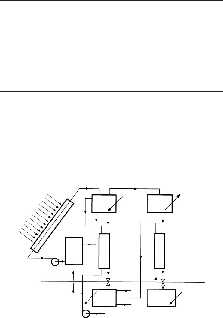
In this example, we present one of our earlier works (Dincer and Ture, 1993; Dincer, Edin and
Ture, 1996) on the design and construction of a solar powered ARS (Figure 4.30) using a mixture
of R-22 and DMETEG as the working fluid. In this project, a combined water-heating and cooling
system based on absorption refrigeration was designed and constructed. The system consists of
four plate collectors, an evaporator, an absorber, a generator, a condenser, a solution pump, and
two heat exchangers. Each part was custom-designed to provide 4000 kcal/h cooling load, although
R-22 which has a less damaging effect on the ozone layer compared to other CFCs was employed
as a refrigerant. The energy analysis results of the experimental system were compared with the
theoretical calculations and a reasonably good agreement was found. The results show that the ARS
appeared to be efficient and effective.
Solar radiation
Collector
Pump
m
s
m
g
m
a
m
g
Generator
5
8
Condenser
Q
c
Q
g
6
4
9
Tank
Heat exchanger
Heat exchanger
13
12
11
10
P
c
P
e
Q
e
W
p
Q
a
3
2
Pump
1
7
Expansion
valve
Water in
Water out
Expansion
valve
Evaporator
Absorber
Figure 4.30 An R-22 and DMETEG ARS (Dincer et al., 1996) (Reprinted with permission from Elsevier
Science).

198 Refrigeration Systems and Applications
Solution
In the energy analysis, we used the energy balance equations presented earlier in this section.
Experimental Apparatus and Procedure. The experimental system used a working fluid com-
bining R-22 as refrigerant and DMETEG as absorbent. The cycle efficiency and the operational
characteristics of an ARS are dependent on the properties of the refrigerant, the absorbent, and
their relative mixtures. The combination of R-22 and DMETEG was suggested as one of the new
alternative combinations and was employed in the present system.
A schematic diagram of the solar powered ARS built in the Solar Energy Laboratory of the Energy
Systems Department at Marmara Research Centre in Gebze, Turkey, is depicted in Figure 4.30.
Generally, the system is considered as one which incorporates solar energy equipment with con-
ventional ARS. The basic elements of the system were four flat-plate collectors, an evaporator,
an absorber, a generator, a condenser, a solution pump, and two heat exchangers. The system has
been designed specifically to provide 4000 kcal/h cooling load in the evaporator. Although the con-
struction of the components of the system followed closely that of Van Den Bulck, Trommelmans
and Berghmans 1982, some modifications were introduced into the individual components of the
system, not only to achieve the desired design parameters, but also to improve the operation of
the ARS. For instance, a 1.2 m long and 1.3 cm diameter copper pipe with 2 mm holes in every 3 cm
of length was employed in the absorber to provide homogeneous, fast, and effective absorption of
DMETEG and R-22 vapor.
The operation of the system is described as follows. Starting from the change of R-22 from liquid
to gas via the throttling effect of the expansion valve, the resulting R-22 vapor begins to absorb heat
from its immediate surroundings in a conventional natural convection type evaporator. Cool vapor
leaving the evaporator passes through the second heat exchanger into the absorber where it combines
with DMETEG which absorbs the gaseous R22. Absorption proceeds because of the chemical
affinity between the absorbent DMETEG and refrigerant R-22 molecules. This absorption activity
lowers the pressure in the absorber to cause the vapor to flow from the evaporator. When the vapor
goes into liquid solution it releases both its latent heat and a heat of dilution. This energy release
has to be continuously dissipated by the cooling water. When the effective cooling is achieved,
the process continues until the liquid solution reaches the equilibrium saturation condition which
exists for each absorber temperature and pressure. Because of the physical limitations, complete
equilibrium saturation may not be reached in the absorber and the strong liquid leaving the absorber
may not be as fully saturated with R-22 as its pressure and temperature would require. The resulting
liquid solution reaches the equilibrium saturation condition consistent with the temperature and
pressure of the absorbent. This strong solution, fully saturated with R-22, now passes through
a solution pump which raises the pressure, passing it through the first heat exchanger and into
the generator. The generator meanwhile is being heated by circulating hot water in the higher-
pressure portion of the system, whose heat is derived from the solar collectors. The temperature of
the strong R-22/DMETEG solution increases, driving off R-22 and a small amount of DMETEG
vapor. The weak solution returns to the absorber down through the first heat exchanger while
warming the upward flowing strong solution. It is then throttled into the absorber by the expansion
valve, to be further cooled as it picks up a new charge of R-22 coming from the second heat
exchanger. Meanwhile, the hot R-22 vapor driven off in the generator passes to the condenser where
it loses energy and passes into the liquid phase. The liquid R-22 after passing down through the
second heat exchanger experiences a drop in pressure and enters the evaporator as the low portion
of the system to complete the cycle. The reduction in pressure through this valve 2 facilities the
vaporization of R-22 which ultimately effects the heat removal from the environment. The cycle
is completed when the desired cooling load is achieved in the evaporator. Consequently, it can be
Refrigeration Cycles and Systems 199
seen that there are essentially three circuits for the absorption cooling system; (a) the almost pure
R22 circuit – condenser, heat exchanger 2, evaporator, and heat exchanger 2 to the absorber, (b) the
strong solution circuit – absorber, pump, and heat exchanger 1 to the generator, and (c) the weak
solution circuit – from the generator through the heat exchanger 1 and into the absorber.
Results and Discussion. All the required parameters for the design of a solar powered absorption
cooling system were obtained by using the calculation techniques for the individual components.
In the theoretical calculations for the design of an ARS, an enthalpy–concentration diagram for the
R-22 and DMETEG pair (Figure 4.30) was used. Some obtained results are as follows: T
1
...T
13
(
◦
C) =39, 30, 30, 65, 90, 87, 53, 82, 40, 27, −5, −5, 20; T
cw
= 20
◦
C; P
e
= 4.8bar;P
c
= 16 bar;
Q
e
= 4.65 kW; Q
c
= 5.0kW;Q
a
= 7.5kW;Q
g
= 7.6kW;W
p
= 0.25 kW; COP = 0.6; m
s
=
290.6 kg/h; m
g
= 90.0 kg/h; m
a
= 200.6 kg/h. In addition, some results related to the collector
system are as follows: L = 40
◦
46
; S = 36
◦
; Q
th
= 4313 kcal/m
2
·day; R = 1.08; E
c
= 0.65; E
m
=
0.60; E
g
= 0.80; T
w
= 45
◦
C; T
s
= 18.7
◦
C; Q
u
= 1450 kcal/m
2
·day; m = 420 kg/day; C
p
= 1
kcal/kg·
◦
C; F
c
= 8m
2
; n = 4; V = 0.48 m
3
; G = 8 L/min; ε
1
= 0.06 m
3
/m
2
; f
2
= 1 L/min·m
2
;
Q
r
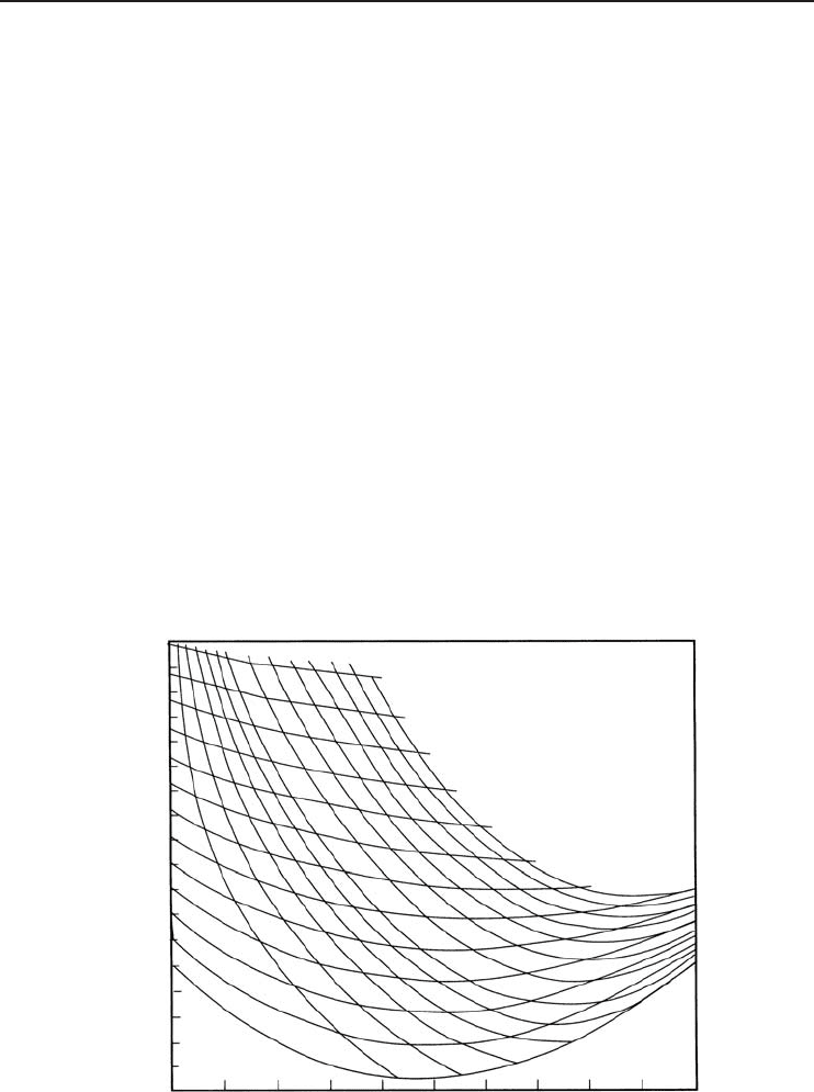
= 1,1046 kcal/day. Note that Figure 4.31, known as the enthalpy–concentration diagram of
the R-22/DMETEG pair, was used to find the enthalpy and other relevant data. This graph was
originally developed by Jelinek, Yaron and Borde 1980.
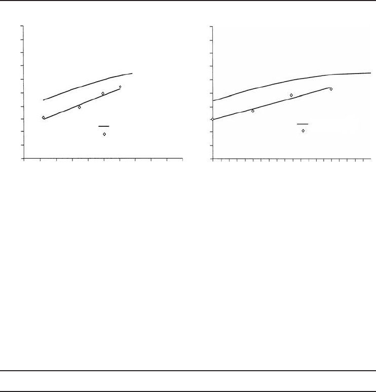
Under a working regime, the measured experimental and theoretical values were used to deter-
mine the values of COP which were plotted against the variations in evaporator temperature as
shown as Figure 4.32a. In this graph, in order to eliminate the negative evaporator temperatures,
the term (T
a
− T
e
) was used where T
a
is the initial evaporator temperature whose average value
DMETEG–R22
Temperature (°C)
Pressure (kg/cm
2
)
165
160
155
150
145
140
135
130
125
120
115
110
105
100
95
90
85
80
75
Enthalpy, h (kcal/kg)
0 0.1 0.2 0.3 0.4 0.5 0.6 0.7 0.8 0.9 1.
0
Weight fraction (x)
120
110
100
90
70
80
60
50
40
30
20
10
0
20
18
16
14
12
10
8
6
5
4
3
2
1
Figure 4.31 Enthalpy-weight fraction (concentration) diagram for the pair of R-22 and DMETEG (Dincer
et al., 1996) (Reprinted with permission from Elsevier Science).
200 Refrigeration Systems and Applications
1.0
0.9
0.8
0.7
0.6
0.5
0.4
0.3
0.2
0.1
0.0
COP
1.0
0.9
0.8
0.7
0.6
0.5
0.4
0.3
0.2
0.1
0.0
COP
20 22 24 26 28 30
T
a
−T
e
(°C) T
g
(°C)
Theoretical
Experimental
Theoretical
Experimental
80 82 84 86 88 90 92 94 96 98 100
(a) (b)
Figure 4.32 Variation of COP versus (a) evaporator temperature and (b) generator temperature (Dincer et al.,
1996) (Reprinted with permission from Elsevier Science).
was around 20
◦
C. The experimental evaporator temperature values which were found to be lower
than that of the theoretical ones clearly indicated some heat losses in the system. Similarly, when
the actual and theoretical values of COP were plotted against the variation of generator temperature
(Figure 4.21b) a slight increase in COP with increasing temperature was observed. This indicated
that the operating performance of the system can be considered stable in that range of temperatures.
Although the cost of the system was higher than that of compression refrigerators of equivalent
performance (almost double), it is believed that the basic design is amenable to low cost mass
production. This makes it attractive for widespread use especially in developing countries. In
addition, it must be remembered that this system was developed and built as a one-off research
prototype. Refinement of the manufacturing process and economical selection of materials will
further reduce the cost per unit.
Example 4.8
In this example, we present one of our works (Dincer and Dost, 1996) on energy analysis of a lithium
bromide–water ARS to determine heat and work capacities of the system’s components varying
with the mass flow rates of weak solution. The heat and work capacity expressions developed, based
on optimum operation conditions, are proposed as useful equations for practical design calculations
of lithium bromide–water ARSs.
In the energy analysis, we used the mass and energy balance equations for the system shown in
Figure 4.33, based on the methodology presented above.
The main goal was to find simple expressions that can be utilized in design calculation of
lithium bromide–water ARS. We considered some optimum design parameters, such as evaporator
temperature T
E
= 4.5
◦
C, condenser and absorber temperatures T
C
= T
A
= 30
◦
C, heat exchanger
efficiency E = 0.9 for two cases of the generator temperatures T
G
= 90 and 100
◦
C. For comparison
purposes, two temperature values of the generator were investigated. In addition, the concentration
values of LiBr on a mass basis were taken as X
a
= 0.685 and 0.695 for weak solution, and X
s
= 0.5
for strong solution to avoid crystallization at the two generator temperatures given above, using
Figure 4.34. Using the optimum conditions, the following temperature and enthalpy values for two