Graef M. Introduction to conventional transmission electron microscopy
Подождите немного. Документ загружается.


138 The transmission electron microscope
Table 3.1. Partial chronology of the history of the electron and the electron
microscope, and other events which have had a significant impact on the
microscopy field, with references to fundamental papers.
Year Event
1871 Cromwell Fleetwood Varley suggests that the carriers of electricity are
corpuscular, with a negative charge [Var71]
1876 Eugene Goldstein studies discharges in gases, and coins the name cathode rays,
starting a long debate about their nature [Gol76]
1891 George Johnstone Stoney coins the word electron for the unit of charge [Sto91]
1897 Emil Wiechert is the first to obtain reasonable bounds on the magnitude of e/m
(January) [Wie97]
1897 Walter Kaufmann and J.J. Thomson
independently measure
e/m (April)
[Kau97, Tho97]
1899 J.J. Thomson determines the value of e, which makes him the discoverer of the
electron [Tho99]
1905 Albert Einstein publishes the special theory of relativity and establishes the
equivalence of mass and energy [Ein05]
1913 Niels Bohr introduces a model for the structure of the hydrogen
atom [Boh13a,
Boh13b,
Boh13c]
1923 Maurice de Broglie establishes the principle of wave–particle duality [de 23]
1925 Wolfgang Pauli discovers the exclusion principle; Werner Heisenberg
develops matrix quantum mechanics [Pau25, Hei25]
1926 Erwin Schr¨odinger develops quantum mechanics based on differential
equations; Hans Busch develops the theory of magnetic lenses [Sch26,
Bus26]
1927 Clinton Davisson and Lester Germer discov
er electron diffraction [DG27]
1928 Paul Dirac formulates the relativistic theory of the electron; Hans Bethe
develops the first dynamical theory of electron diffraction [Dir28a, Bet28]
1931–4 Ernst Ruska and Max Knoll build the first electron microscope [KR32a, KR32b,
Rus34a, Rus34b]
we refer the interested reader to the book The Growth of Electron Microscopy,
edited by T. Mulvey [Mul96].
3.3 Overview of the instrument
Since the first electron microscope was constructed by Ruska and Knoll, TEMs have
evolved into complex computer-controlled machines, and many of the underlying
physical principles are hidden from the user in modern machines. Students who
learn to operate the latest (digital) model as their first machine may find it hard
to operate some of the earlier models, especially the ones where lens and gun
alignment are mostly mechanical. An inexperienced user should be aware of the
fact that different microscope models may have a different layout of the most
3.3 Overview of the instrument 139
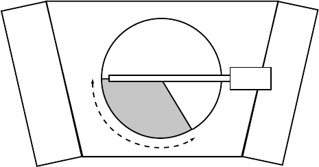
120°
Specimen rod
Fig. 3.1. Schematic top view of the section removed from the JEOL 120CX microscope
column; the specimen holder location is also indicated.
commonly used controls and that some “mental adjustments” may be needed when
moving from one instrument to another. The contents of this and the following
chapter should provide some common ground for the operation of all microscope
models.
An optical microscope, used in transmission mode, typically consists of five
parts: the light source; the condensor lens, which focuses the light beam onto the
sample; a transparent sample, usually a thin section of rock or tissue; the objective
lens, sometimes in contact with the sample through a contact medium (oil); and
the magnifying lens(es), often combined with the ocular or eyepiece. The number
of lenses may vary but most optical microscopes have all five components. A TEM
can be divided into similar sections. The five sections of a TEM are (from top
to bottom): the electron gun, the illumination stage, the objective lens, with an
electron transparent sample immersed into its magnetic field, the magnification
and projection system, often with three or more lenses, and the detector (a viewing
screen, photographic camera, charge-coupled device (CCD) camera, etc.
A cross-section of a JEOL 120CX microscope column is shown on the right in
Fig. 3.2.
†
A corresponding schematic drawing, taken from the microscope manual,
is shown on the left, along with an outline of the five main components.
†
Several of the photographs in this chapter were obtained from a cross-section of a real TEM, a JEOL model
120CX, built in 1978 (serial number EM 156049-17). Throughout the second half of 1999 the author, with
the help of Mr N.T. Nuhfer and Mr G. Biddle, removed a 120
◦
lengthwise wedge from the column, using a
high-capacity band saw. One edge of the wedge cut is along the leftmost (when facing the microscope) side of
the goniometer stage, the other cut is at 60
◦
from the opposite side, as illustrated in the schematic top view in
Fig. 3.1. The cut extends from the top of the electron gun down to the top of the viewing chamber, over a length
of approximately 1060 mm; the viewing chamber itself was left intact, to provide sufficient mechanical support
to the column. The surfaces of the cuts were sanded to a smooth finish and covered with a protective layer of
polyurethane, to minimize corrosion. After completion of all the cuts, the microscope column was reassembled
at the bottom of the stairwell on the ground floor of Roberts Engineering Hall, Carnegie Mellon University
campus. Additional photographs of the cross-section are available from the
website.
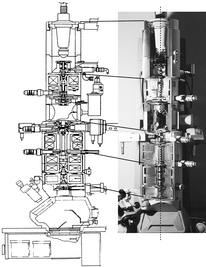
140 The transmission electron microscope
electron gun
illumination
objective
lens
magnification
observation
optical axis
Fig. 3.2. Schematic drawing
and photograph of a real cross-section of a JEOL 120CX
transmission electron microscope, with the main stages outlined. (Drawing reproduced
with permission.)
3.3 Overview of the instrument 141
In addition to the five main stages listed above, a TEM contains a number of
subsystems that are vital for proper operation, but are of secondary importance to
the operator during routine use of the microscope.
†
r
The high voltage system. This system is usually located in a separate unit and is connected
to the electron gun by a thick cable. For acceleration voltages of 400 kV and higher, this
type of cable connection is no longer possible and the accelerator is placed just behind
the microscope column or on top of the column.
r
The vacuum system. Electrons need a good vacuum (in the range of 10
−7
–10
−10
Pa (or
10
−5
–10
−8
torr, where 1 torr = 133.322 Pa) to travel the typically 1–2 m length of the
column, hence every TEM is equipped with a high vacuum system. The system generally
consist of one or more roughing pumps, possibly with a vacuum buffer tank, one or more
oil diffusion pumps and/or ion getter pumps and/or turbomolecular pumps, and a num-
ber of independent vacuum circuits with manual or automatic (pneumatic or electronic)
valves. Some microscopes are modified for ultra-high vacuum conditions, which means
that the partial pressures of all gases in the column are better than 10
−8
torr. In older
microscopes, such as the Siemens Elmiskope 102, the operator had to be familiar with
the pumping diagrams and cycles and often manually open or close valves. Nowadays,
this task is fully automated and interlocks on the high voltage system and the filament
emission system will prevent the operator from using the machine if the vacuum level is
inadequate.
The operator should always take note of the proper vacuum level at which the micro-
scope must be operated. This should be part of the prework checklist. The vacuum is
usually best in the electron gun and slightly worse at the specimen stage. Some micro-
scopes allow observations at near ambient pressures in a variety of gas mixtures through
the use of an environmental specimen cell; in those cases the sample region is separated
from the rest of the microscope column by differential pumping apertures.
In older microscopes, such as the JEOL 120CX, the vacuum region of the microscope is
separated from the rest by about two-dozen O-rings. In modern instruments the electrons
travel through so-called liner tubes, long cylindrical sections with a small inner diameter
(a few millimeters), which extend across several lenses and reduce the total number of
vacuum seals needed.
r
The cooling system. Large electric currents can generate a lot of heat (Ohm’s law), hence
the lens coils, which can carry several amperes of current, must be water-cooled. This
system is fully automatic and the operator should never have to intervene at any point.
The cooling system is interlocked with other systems, so that the microscope cannot be
used if insufficient cooling water is available.
r
Radiation shields. All electrons emitted by the filament must eventually find their way
back into the electrical circuit, and must get rid of their kinetic energy. All surfaces
†
A TEM operator should be aware of the meaning of the warning signs and indicator lights should any of the
subsystems described in this section malfunction or cause problems. We refer to the microscope manual for a
detailed description of all subsystems.
142 The transmission electron microscope
inside the column that may be exposed to electrons are therefore made of a conductive
material. A more serious problem is posed by the conversion of kinetic energy into x-ray
photons wherever the electrons enter solid matter. All areas of the microscope where
x-rays may be generated are therefore surrounded by a double shield: the first layer of the
shield is a low atomic number material, typically aluminum, which converts most of the
kinetic energy into low-energy x-ray photons. The second layer is a high atomic number
material, typically lead, which efficiently absorbs the low-energy x-ray photons. The
viewing window is made of a special lead containing glass and can be rather expensive.
The radiation shields contribute significantly to the weight of the column, and are thicker
for higher-energy microscopes.
r
The photographic camera system. A photographic camera, consisting of two removable
boxes, is mounted below or behind the viewing screen: one box contains unexposed
plates and the other one receives the exposed plates (depending on the microscope type
the number of available plates can vary anywhere from 20 to 50). The exposure time and
film sensitivity can be set
from the microscope console, although one should not change
the latter unless the type of film is changed. All microscopes indicate the magnification
(or camera length for diffraction) and the plate serial number near the edge of the negative;
some models also allow for the
inclusion of 30 or so characters of text, to identify the
operator and sample.
This concludes the enumeration of the more common microscope subsystems.
Possible additional subsystems include energy dispersive analyzers for x-rays or
electron energy loss spectroscopy (EDS and EELS), cameras (TV rate, CCD, or
imaging plate), scanning attachments, various detectors before and after the sample,
imaging energy filters, etc. With the exception of electron detectors, we will not
address these additional subsystems in this book.
3.4 Basic electron optics: round magnetic lenses
3.4.1 Cross-section of a round magnetic lens
In a light optical microscope, glass lenses are used to first focus a light beam onto the
sample, and then magnify the image to the desired magnification. Each lens is a care-
fully shaped piece of glass. The radius of curvature of each surface along with the
refractive index of the glass determine the optical properties and quality of the lens.
Glass lenses have been used since the early compound (multi-lens) microscopes
built by Zacharias Jansen in 1595 and the high-quality single-lens microscopes
built by Anton Leeuwenhoek in the second half of the seventeenth century [Jon97].
Light optics has become a highly developed field, with numerous applications that
affect us in our daily lives. Cameras, CD players, lens and mirror-based telescopes
are only a few examples of the widespread availability of high-quality optics; light
3.4 Basic electron optics: round magnetic lenses 143
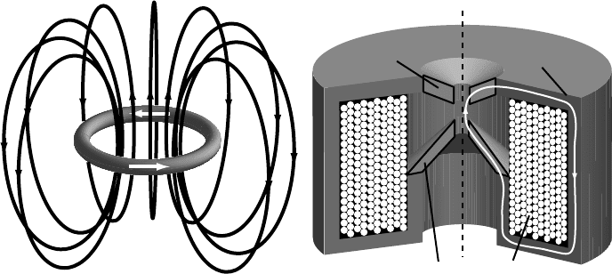
optical axis
upper polepiece
lower
polepiece
lens coil
yoke
(a)
(b)
Fig. 3.3. (a) Schematic representation of the magnetic field lines around a circular current-
carrying coil; (b) a magnetic yoke concentrates the field lines near the center of the coil and
provides a particular geometry to the field.
optical systems can be designed and built to any specifications, with virtually no
aberrations at all.
Deflection of electrons requires magnetic or electrostatic lenses. All modern
transmission electron microscopes contain at least six and often more than six
round magnetic lenses. The main purpose of a round magnetic lens is to focus the
electron beam towards the optical axis. The basic principle behind such a lens is
shown in Fig. 3.3(a): a circular current running through a coil produces a magnetic
field that is nearly axial at the center of the coil. We know from electromagnetism
that the strength of the field obtained at the center of the coil is proportional to the
magnetic permeability of vacuum (or air) [Jac75]. We can significantly increase the
attainable field strength by using a solid yoke with a large magnetic permeability
to guide the field lines and increase the field strength near the center of the coil
(Fig. 3.3b). The details of the shape of the pole pieces near the center will determine
the precise geometry of the magnetic field.
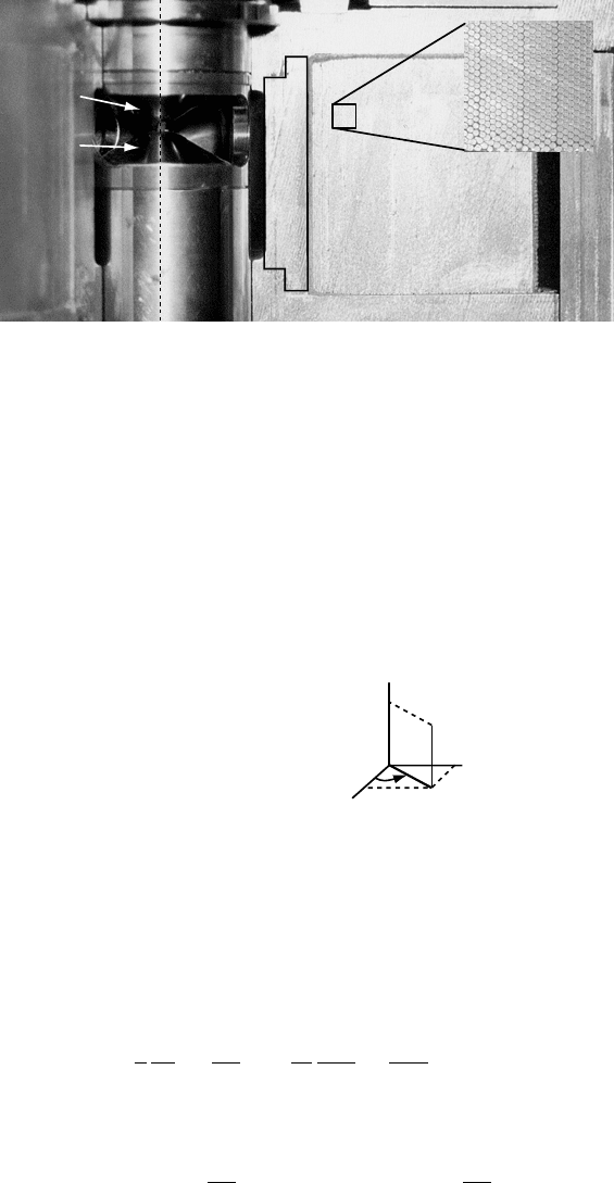
A cross-section of a real magnetic lens (the first condensor lens of a JEOL120CX)
is shown in Fig. 3.4; the large rectangular area to the right is the tightly packed
copper winding, as shown in the inset. The upper and lower portions of the yoke
are separated by a brass spacer. The lens pole pieces, typically made of a high-
permeability Fe–Co alloy, are visible to the left of the winding. The magnetic field
strength is highest near the optical axis in between the upper and lower pole pieces.
The distance between the upper and lower pole pieces is known as the lens gap.
While the geometrical details may vary from one lens to the next, all round magnetic
lenses are basically identical in design to the lens shown in Fig. 3.4. Next, we will
144 The transmission electron microscope
1st condensor
coil
brass spacer ring
upper
lower
pole
piece
optical
axis
brass spacer ring
yoke
yoke
Fig. 3.4. Cross-section of the first condensor lens of a JEOL 120CX microscope. The coil
winding has an areal density of nearly 300 copper wires per cm
2
. The pole pieces, visible
through the slot on the left, are made of a high-permeability Fe–Co alloy.
take a closer look at the magnetic field components inside a round magnetic lens.
3.4.2 Magnetic field components for a round lens
Let us consider a magnetic field with circular symmetry around its central axis.
It is convenient to employ cylindrical coordinates (r,ϕ,z), related to the standard
Cartesian coordinates (x, y, z) by the relations:
x = r cos ϕ;
y = r sin ϕ;
z = z.
x
y
z
r
ϕ
(3.1)
The z-axis is taken to be the symmetry axis of the field. In the absence of field-
producing currents, we can use a scalar magnetic potential ω(r, z), satisfying the
homogeneous Laplace equation ω = 0, to derive the magnetic field components
B =−µ∇ω [Jac75] (µ is the permeability). This potential does not depend on the
azimuthal angle ϕ because of the rotational symmetry.
The Laplace equation in cylindrical coordinates is given by (e.g. [Jac75])
1
r
∂
∂r
r
∂ω
∂r
+
1
r
2
∂
2
ω
∂ϕ
2
+
∂
2
ω
∂z
2
= 0,
and the magnetic field components are given by
B
r
=−µ
∂ω
∂r
and B
z
=−µ
∂ω
∂z
.

3.4 Basic electron optics: round magnetic lenses 145
Following Szilagyi [Szi88], we will express the potential ω(r, z) as a radial series,
as follows:
ω(r, z) =
∞
i=0
a
i
(z)r
i
. (3.2)
After substitution into the Laplace equation we find
∞
i=−2
(
i + 2
)
2
a
i+2
(z)r
i
+
∞
i=0
a
(2)
i
(z)r
i
= 0,
where the superscript (2) denotes the second-order derivative with respect to z.For
i =−1 we find a
1
(z) = 0 and therefore all odd functions a
2i+1
(z) vanish. Denoting
a
0
(z)byU (z) we also find
a
2
(z) =−
U
(2)
(z)
4
;
a
4
(z) =−
a
(2)
2
(z)
16
=
U
(4)
(z)
64
;
a
6
(z) =···
from which we find the general relation
a
2i
(z) =
(−1)
i
4
i
(i!)
2
U
(2i)
(z). (3.3)
This leads to the following expression for the scalar magnetic potential:
ω(r, z) =
∞
i=0
(−1)
i
U
(2i)
(z)
(
i!
)
2
)
r
2
*
2i
. (3.4)
If we define the axial flux density B(z)by
B(z) =−µ
∂ω
∂z
#
#
#
#
r=0
,
then we find for the field components
B
r
=
∞
i=1
(−1)
i
B
(2i−1)
(z)
i!(i − 1)!
)
r
2
*
2i−1
=−B
(z)
r
2
+ B
(3)
(z)
r
3
16
−···; (3.5)
B
z
=
∞
i=0
(−1)
i
B
(2i)
(z)
(i!)
2
)
r
2
*
2i
= B(z) − B
(z)
r
2
4
+ B
(4)
(z)
r
4
64
+···. (3.6)
In other words, the magnetic field components for a round lens at any point in space
are completely determined by the flux density B(z) along the optical axis and all of

146 The transmission electron microscope
its derivatives. We will use the series expansions above to derive the paraxial ray
equation for a round magnetic lens in the next sections.
There are many different techniques for computing electrostatic and magnetic
fields, many of them relying on some form of Laplace’s equation for a domain with a
boundary of complicated shape. Finite element methods are among the more popular
methods for the calculation of fields. For an extensive review of these methods and
experimental measurements of field configurations we refer to [HK89a, Chapters
6–13] and [Szi88, Chapter 3].
3.4.3 The equation of motion for a charged particle in a magnetic field
We have seen in Chapter 2 that electrons in a TEM must be treated as relativistic
charged particles. Newton’s equation of motion,
dp
dt
= F,
with p = mv the so-called kinetic momentum and F the total external force, can
be rewritten for a particle with charge −|e| in an arbitrary, time-dependent electro-
magnetic field:
dp
dt
=
d(mv)
dt
=−|e|[E(r, t) + v × B(r, t)]. (3.7)
The right-hand side is the Lorentz force, a velocity-dependent force. If the mass m
is written in the relativistic form γ m
0
, then equation (3.7) describes the relativistic
motion of an electron. We recall that the magnetic field B can be written as the curl
of the magnetic vector potential A (B =∇×A) or as the gradient of the magnetic
scalar potential ω in the absence of currents in the field region, and the electric field
E is equal to −∇ with the electrostatic potential [Jac75]. For a conventional
transmission electron microscope, the electrostatic potential is zero along most of
the electron trajectory, except for the initial acceleration by the voltage E, and the
electrostatic lattice potential V (r) inside the crystal.
Equation (3.7), with B = 0, is used to describe the electron optical characteristics
of electron guns and electrostatic deflectors. For E = 0, the equation describes a
purely magnetic field, and it is the starting point of trajectory analysis procedures
for magnetic lenses. The design of an electromagnetic device thus consists of two
separate problems:
(i) for a given electrode or lens geometry, the field must be computed;
(ii) then, with this field, the trajectory equation must be solved for particles traveling at
various distances from the electrode surfaces or the optical axis of the lens.
For a very general derivation of the relativistic trajectory equations for a combined
electrostatic and magnetic field distribution in arbitrary curvilinear coordinates
3.4 Basic electron optics: round magnetic lenses 147
we refer to Szilagyi [Szi88, Chapter 2], whose derivation starts from the Euler–
Lagrange equations of motion. The equations of motion derived in this way are
valid for a general time-dependent magnetic field, and are thus applicable to a wide
range of field geometries, including synchrotrons, particle accelerators, electron
microscopes, cathode ray tubes, and so on. It should come as no surprise that the
literature on the subject of charged particle dynamics is vast, going back to the
second half of the nineteenth century. We refer the interested reader to the volumes
on Principles of Electron Optics [HK89a, HK89b] for an extensive list of papers
relevant to electron microscopy.
For the purposes of this textbook, it will be sufficient to derive the relevant
equations from the Lorentz equation of motion (3.7) in cylindrical coordinates.
The basis vectors of the cylindrical coordinate system are dependent upon the
particular point were they are considered:
e
r
= cos ϕ e
x
+ sin ϕ e
y
;
e
ϕ
=−sin ϕ e
x
+ cos ϕ e
y
;
e
z
= e
z
.
(3.8)
The time derivatives are given by (denoting a derivative with respect to time by a
dot above the variable):
˙
e
r
= ˙ϕ e
ϕ
;
˙
e
ϕ
=−˙ϕ e
r
;
˙
e
z
= 0.
(3.9)
The velocity vector is given by
v =
˙
r e
r
+r ˙ϕ e
ϕ
+
˙
z e
z
. (3.10)
We now have all the tools we need to express the Lorentz equation in cylindrical
coordinates, and after a simple computation (taking E = 0) we find the following
three component equations:
d(m
˙
r)
dt
− mr ˙ϕ
2
=−|e|r ˙ϕ B
z
; (3.11)
d(mr ˙ϕ)
dt
+ m
˙
r ˙ϕ =−|e|[
˙
zB
r
−
˙
rB
z
]; (3.12)
d(m
˙
z)
dt
=|e|r ˙ϕ B
r
;
where m =
m
0
1 −
1
c
2
(
˙
r
2
+r
2
˙ϕ
2
+
˙
z
2
)
. (3.13)
In this derivation we have used the fact that B
ϕ
= 0, as it must be for an axially sym-
metric field distribution. These equations are non-linear, coupled partial differential