Graef M. Introduction to conventional transmission electron microscopy
Подождите немного. Документ загружается.

168 The transmission electron microscope
axis. The point P
o
has coordinates (x
o
, y
o
) in the object plane, and is represented
by the complex number u
o
= x
o
+ iy
o
. The distance between P
o
and the optical
axis is then given by r
2
o
= u
o
u
∗
o
. The point P
a
is similarly described by the complex
number u
a
= x
a
+ iy
a
. We will assume that the image rotation along the optical
axis has been absorbed into the definition of the respective coordinate frames. It can
then be shown that the image point P
i
is located at the position u
i
+ u
i
, where u
i
is the Gaussian position, and
u
i
= Cr
2
a
u
a
← spherical aberration
+2(K + ik)r
2
a
u
o
+ (K − ik)u
2
a
u
∗
o
← coma
+(A + ia)u
2
o
u
∗
a
← astigmatism
+ Fr
2
o
u
a
← field curvature
+(D + id)r
2
o
u
o
← distortion. (3.42)
The eight constants C, K , k, A, a, F, D, and d are the real
†
aberration coefficients;
they describe the five primary or Seidel aberrations. The magnification factor M
has been omitted for clarity. The primary aberrations can be grouped into three
categories: the aperture aberrations (terms independent of the object position u
0
in equation 3.42), the chromatic aberrations (terms independent of u
a
, discussed
in Section 3.7.4) and the parasitic aberrations (in general these are linear in u
o
or
linear in u
a
). Geometric aberrations are caused by the properties of the magnetic
field. Chromatic aberrations are caused by the instabilities in the lens current and/or
instabilities in the acceleration potential; they give rise to slightly different electron
trajectories in the lens and hence to a blurring of the image. Finally, parasitic
aberrations are caused by inhomogeneities or imperfections in the lens pole pieces,
deviations from perfect circular symmetry, etc.
The first term in equation (3.42), spherical aberration, is of third order in the
coordinates u
a
, and hence also of third order in the angle α between the trajectory
and the optical axis. The next distortion, coma, is of second order in α, and is
described by two numbers K and k, which can be converted into an amplitude and
angle, i.e. a single complex number. The next two aberrations, astigmatism and
field curvature, are linear in α; astigmatism is also represented by two numbers
A and a. Finally, the fifth aberration, known as distortion, only depends on the
position in the object plane, and is also described by two numbers D and d. Each of
the aberrations describes a particular way in which the wave front can depart from
the spherical shape. The true wave front shape is a linear superposition of the five
aberrated wave fronts. Next, we will describe briefly the nature of the five Seidel
aberrations.
†
One can also define asymptotic aberration coefficients for projector lenses.
3.5 Basic electron optics: lens aberrations 169
P
o
P
i
Circle of least
confusion
α
MC
s
α
3
r
a
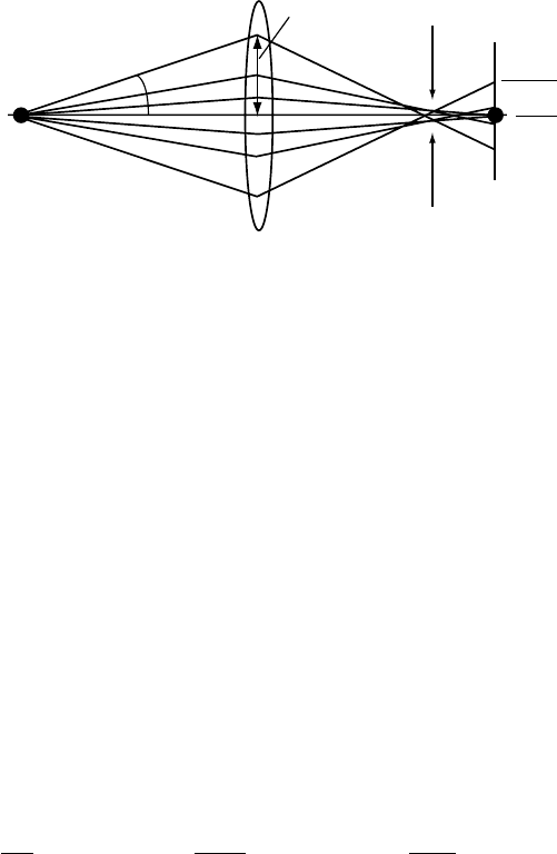
Fig. 3.13. Spherical aberration of rays far from the optical axis.
3.5.2.1 Spherical aberration
The nature of spherical aberration can be understood by considering the first term
in equation (3.42) and rewriting the position vector u
a
in polar coordinates for a
circle of radius r
a
in the lens plane: u
a
= r
a
(cos θ + i sin θ), where θ ranges from
0to2π. The correction term then becomes
x
i
+ iy
i
= MCr
3
a
(cos θ + i sin θ),
which is a circle with radius proportional to the cube of the distance r
a
. The circle
does not depend on the location u
o
of the object point. Figure 3.13 shows schemati-
cally how electrons leaving an axial object point are affected by spherical aberration:
rays passing through the outer zone of the lens (i.e. through a circle with a large
radius r
a
) are focused more strongly than the paraxial rays, and will hence come
to a focus before the Gaussian image plane.
†
The spherical aberration coefficient
C
s
(which is proportional to the coefficient C defined above) can be computed in
terms of the axial magnetic field distribution B(z) by:
‡
C
s
=
η
2
8
ˆ
.
z
1
z
0
9
B
(z)
2
+
3e
8m
ˆ
B
4
(z) − B
2
(z)
h
(z)
h(z)
2
h
4
(z)dz, (3.43)
where h(z) is a paraxial trajectory, which leaves an axial object point with unit
slope, i.e. h
(z
o
) = 1 [HK89b]. The presence of powers of the magnetic field in this
expression makes the spherical aberration particularly sensitive to small variations
in the field. In the Gaussian image plane, a point object is imaged as a disk, with
radius
r
i
= MC
s
α
3
. (3.44)
†
The Gaussian image plane is the plane conjugate to the object plane in the absence of aberrations; it can be
computed from Newton’s lens equation, if the object position is known.
‡
There are many different ways to write down the spherical aberration coefficient; the expression above is special
in that it clearly shows that the spherical aberration of a round lens is always a positive quantity. This is known
as Scherzer’s theorem.
170 The transmission electron microscope
The narrowest diameter of the electron beam corresponds to the so-called cir-
cle of least confusion. The spherical aberration coefficient C
s
is typically ex-
pressed in millimeters; modern microscopes have an objective lens with C
s
in
the range 0.5–1.5 mm, while for older models the objective C
s
can be several
millimeters.
From the expression above, we can see that the spherical aberration coefficient
of a round magnetic lens cannot become a negative quantity, i.e. rays affected
by spherical aberration intersect the optical axis before reaching the image plane.
This also means that it is impossible to create a round magnetic lens with zero
spherical aberration, since one can show that a lens with C
s
= 0 does not have
a real image [Cre77]. Spherical aberration correction has been a hot research
topic ever since Scherzer’s discovery of the theorem that now bears his name.
Only recently has technology reached the point where C
s
-correctors are becoming
available commercially, and perhaps the microscopes of the future will have such
built-in correctors as a standard component. The interested reader is encouraged
to consult the following sources: [HK89b, Chapter 41], [CK80], [Ros71], [HU97],
[KDL99]. C
s
reduction and/or correction remains an area of very active research and
development.
3.5.2.2 Coma
The second term in equation (3.42) can be rewritten without loss of generality
by considering the following special case: the object point is fixed at the location
u
o
= x
o
, the aberration coefficient has only one non-zero component (k = 0), and
the electrons pass the lens plane in concentric circles of radius r
a
centered on the
optical axis:
x
i
+ iy
i
= MKx
o
2r
2
a
+ u
2
a
;
= MKr
2
a
x
o
2 + e
i2θ
;
= MKr
2
a
x
o
[
(
2 + cos 2θ
)
+ i sin 2θ
]
.
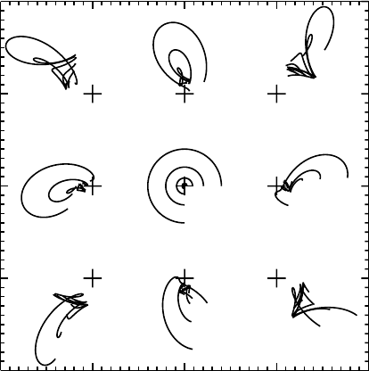
Figure 3.14(a) shows the aberration figure for the conditions: x
o
= 1, M = 1, K =
0.1, and u
i
= 1 + i0. The images of the five concentric circles with increasing
radii r
a
are displaced along the positive x-direction in such a way that the entire
aberration figure is located between two straight lines. This aberration only affects
object points that are not located on the optical axis. The coma coefficients can also
be expressed in terms of special electron trajectories and the axial field B(z); for
explicit expressions we refer the reader to [HK89a].
A more general example of coma is shown in Fig. 3.14(b); eight points are
selected in the object plane at the locations (±1, 0), (0, ±1), and (±1, ±1). The
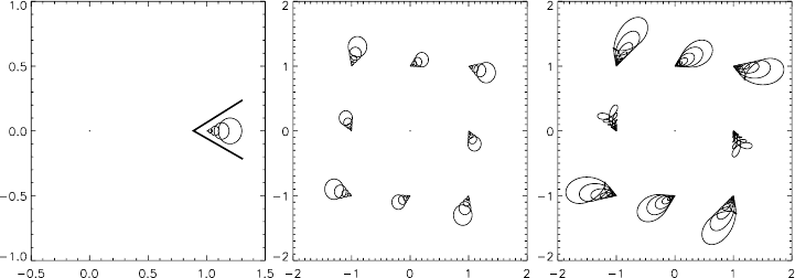
3.5 Basic electron optics: lens aberrations 171
(a)
(b) (c)
Fig. 3.14. Aberration figures due to coma for the parameters described in the text.
coma coefficient is taken to be 0.05 − i0.1, and the concentric circles are centered
on the optical axis. The resulting aberration figures are computed for the same eight
points in the image plane, ignoring the magnification factor. If the concentric circles
are centered on an off-axis point in the lens plane, say the point u
a
= 0.4 + i0.2,
then the aberration figures become more complex and are different for different
object points, as shown in Fig. 3.14(c). Note that the aberration figures remain
located between the same two straight lines, regardless of the position of the point
u
a
. The orientation of the lines is determined by the value of K + ik.
It is clear from the examples in Fig. 3.14 that coma is an undesirable lens aberra-
tion, since it generates extended, asymmetric images of point objects. It is possible
to perform a coma-free alignment of an electron microscope, and we will return to
this in Chapter 10 on phase contrast microscopy.
3.5.2.3 Astigmatism and field curvature
Both astigmatism and field curvature are linear in u
a
, so it is convenient to treat
them together. In the image plane the combined effect of astigmatism (represented
in polar notation as A + ia = Ae
iθ
a
) and field curvature is given by
u
i
= Ar
a
e
i(θ
a
−θ)
x
2
o
− y
2
o
+ 2ix
o
y
o
+ Fr
2
o
r
a
e
iθ
, (3.45)
where the angle θ once again describes a circle of radius r
a
in the lens plane. The
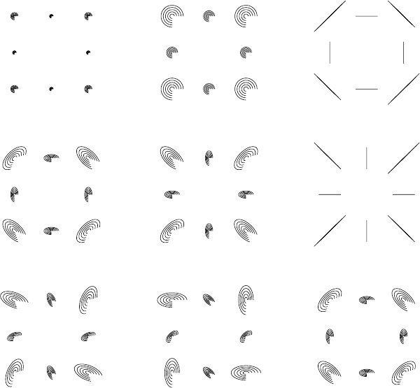
effect of the field curvature term is illustrated in Figs 3.15(a) and (b) for F = 0.05
and 0.15, respectively. The aberration coefficients are shown in the form [A,θ
a
, F].
Note that the angle θ is only varied over three-quarters of a circle; this will be useful
to illustrate the effect of the astigmatism coefficients. The further the object point
is located from the optical axis, the larger its image will be. This is to be contrasted
with the effect of spherical aberration, which results in disks of the same size,
regardless of the position in the object plane.
172 The transmission electron microscope
(a) [0, 0, 0.05] (b) [0, 0, 0.15] (c) [–0.15, 0, 0.15]
(d) [–0.05, 0, 0.15] (f) [0.15, 0, 0.15](e) [0.05, 0, 0.15]
(g) [0.05, 45, 0.15] (h) [0.05, 90, 0.15] (i) [0.05, 180, 0.15]
Fig. 3.15. Illustration of the effect of astigmatism and field curvature (represented in the
form [A,θ
a
, F]) on the image of eight object points aligned on a square. The circle segments
correspond to five circles of increasing diameter in the lens plane.
Consider the point u
o
= 1 + i0, and take θ
a
= 0; the expression above then
simplifies to
u
i
= r
a
Ae
−iθ
+ Fe
iθ
;
= r
a
[
(
F + A
)
cos θ + i
(
F − A
)
sin θ
]
.
It is clear from this expression that for F =±A the aberration figure collapses into
a straight line; this is illustrated graphically in Fig. 3.15(c)–(f).
Another way to represent the effect of astigmatism is through a trajectory dia-
gram. Figure 3.16 shows that the focal length of an astigmatic lens becomes depen-
dent on the azimuthal angle, and varies continuously between two extreme values,
indicated by arrows in the figure. This lens aberration can be completely canceled
by means of quadrupole stigmators. Most microscopes have two sets of stigma-
tors: one for the condensor lens, to remove astigmatism from the incident beam,
and one for the objective lens. Manual astigmatism correction requires considerable
3.5 Basic electron optics: lens aberrations 173
Fig. 3.16. Effect of astigmatism on paraxial rays for a 400 kV electron in Glazer’s bell-
shaped model with B
0
= 0.5 T and a = 3.0 mm; the magnitude of the astigmatism corre-
sponds to a 25% azimuthal change of the magnetic field strength.
(a) (b)
D<0
D>0
D<0
D>0
d= - 0.05
d=0
Fig. 3.17. Schematic illustration of the distortion aberration for D = [−0.3 ...0.3] with
(a) d = 0 and (b) d =−0.05. The original square is outlined in (a).
practice and is generally regarded as one of the more difficult aspects of transmission
electron microscopy. With modern computer-controlled microscopes, astigmatism
correction can be performed entirely and very accurately by a computer algorithm.
3.5.2.4 Distortion
The last Seidel aberration does not depend on the position u
a
in the lens plane and is
illustrated in Fig. 3.17. The distortions for d = 0 are known as pin-cushion distor-
tion (for D > 0) and barrel distortion (for D < 0). For d = 0 an additional torsional
distortion is superimposed on the barrel or pin-cushion shapes, as illustrated in
Fig. 3.17(b). The distortion aberration is only important in the low-magnification
174 The transmission electron microscope
spherical aberration
0.4
field curvature
-0.1
astigmatism
0.1, 45∞
distortion
0.1, 10∞
coma
0.1, 0∞
u
a
= 0+0i
-2 -1
01 2
-2
-1
0
1
2
Fig. 3.18. Illustration of the output of the ION routine seidel.pro for the lens aberrations
stated.
range of a microscope and can be ignored safely for most higher-magnification
work.
3.5.2.5 Combination of the five Seidel aberrations
It is now straightforward to combine all five Seidel aberrations into a single illustra-
tion (Fig. 3.18), so that the total effect of the aberrations can be studied. The reader
may access the ION routine
seidel.pro from the website to enter various combi-
nations of primary aberration coefficients. The routine will return the aberration
figures for nine points on a square in the object plane, with five circles of linearly
increasing radii around an arbitrary point in the lens plane.
3.6 Basic electron optics: magnetic multipole lenses
The example trajectory computations of Section 3.4 illustrate a rather simple way
to deal with electron optical elements. In the absence of currents inside the field
region, one starts from expressions for the magnetic scalar potential ω obtained
as solutions of Laplace’s equation. By making judicious use of the symmetry of
the problem, significant simplifications can often be introduced. For instance, the
general expression for the magnetic scalar potential in cylindrical coordinates is

3.6 Basic electron optics: magnetic multipole lenses 175
given by
ω(r,ϕ,z) =
∞
m=0
[
a
m
(r, z) cos mϕ + b
m
(r, z) sin mϕ
]
.
For a round magnetic lens only the term in m = 0 survives, and this leads to
the radial series expansion in equation (3.2). There are many other magnetic or
electrostatic elements which do not have rotational symmetry, but instead display
a number N of symmetry elements; such elements are known as multipole lenses.
In the presence of N symmetry planes, the magnetic scalar potential must satisfy
the relation [Szi88]
ω(r,ϕ,z) = ω
r,ϕ±
2πl
N
, z
,
from which we can derive that
ω(r,ϕ,z) =
∞
n=0
a
nN
(r, z)r
nN
cos(nNϕ).
For a detailed discussion of this expression and relations derived from it we refer
to [Szi88, Chapter 3] and references therein. For the purposes of this textbook it
will suffice to discuss briefly the standard magnetic quadrupole, and electrostatic
deflectors, because they are common components in a microscope column.
A round magnetic lens does not exert a direct radial force on an electron traveling
nearly parallel to the optical axis. The small radial force which brings the electron
closer to the optical axis is entirely due to the azimuthal velocity component ac-
quired as a consequence of the cross product nature of the Lorentz force. Multipole
elements can be used to exert mostly radial forces on the electron beam, and the sim-
plest multipole field is that present in a beam deflector. The main purpose of a beam
deflector is to provide a lateral shift of the entire beam, with as little disturbance of
the beam structure as possible [HK89a]. In other words, the ideal deflector simply
moves the beam around, without changing its shape. The currents required to run
magnetic deflectors and quadrupoles are substantially less than those required for
round magnetic lenses. While round lenses require anywhere between 1 and 15 A,
deflection coils typically use 10–500 mA and are reversible, i.e. the direction of
the current can be reversed. Correction coils use even less current, typically in the
range of 1–200 mA [Szi88].
There are several beam deflection systems in a standard TEM. On the micro-
scope console they are commonly labeled as beam shift, beam tilt, image shift, and
so on. In addition, many microscopes have a scanning attachment as part of the
illumination system; the incident beam can then be scanned periodically along a
line or a rectangular area on the sample, and various detectors measure a scattered
176 The transmission electron microscope
signal (e.g. secondary or back-scattered electrons), fully synchronized with the
incident beam. The scan coils used for this purpose are essentially high-speed
beam deflectors, somewhat similar in nature to the deflection system in a television
tube.
While a good deflector does not appreciably change the shape of the electron
beam, a quadrupole lens (or rather a pair of quadrupole lenses) is used to adjust
the beam shape, in particular to correct astigmatism. In the next two sections we
will discuss briefly the main characteristics of deflectors and quadrupole lenses.
There is also an extensive literature on the aberrations of multipole elements. This
is far beyond the scope of this book, and we refer the interested reader to [HK89a,
Chapters 29 and 32] and references therein.
3.6.1 Beam deflection
Beam deflectors can consist of electrostatic or magnetic components. The main
purpose of a deflector is to change the direction of the electron beam with re-
spect to the optical axis. Electrostatic deflectors usually consist of two pairs of
electrodes oriented perpendicular to each other, one providing deflection in the x-
direction, and the other in the y-direction. More complex designs with multiple elec-
trodes are also commonly used. Magnetic deflectors are usually used for scanning
applications.
While the electron optical characteristics of deflectors are interesting in their
own right, it is not necessary to discuss them in detail. For the “average micro-
scopist” it suffices to point out that there are two different operation modes for
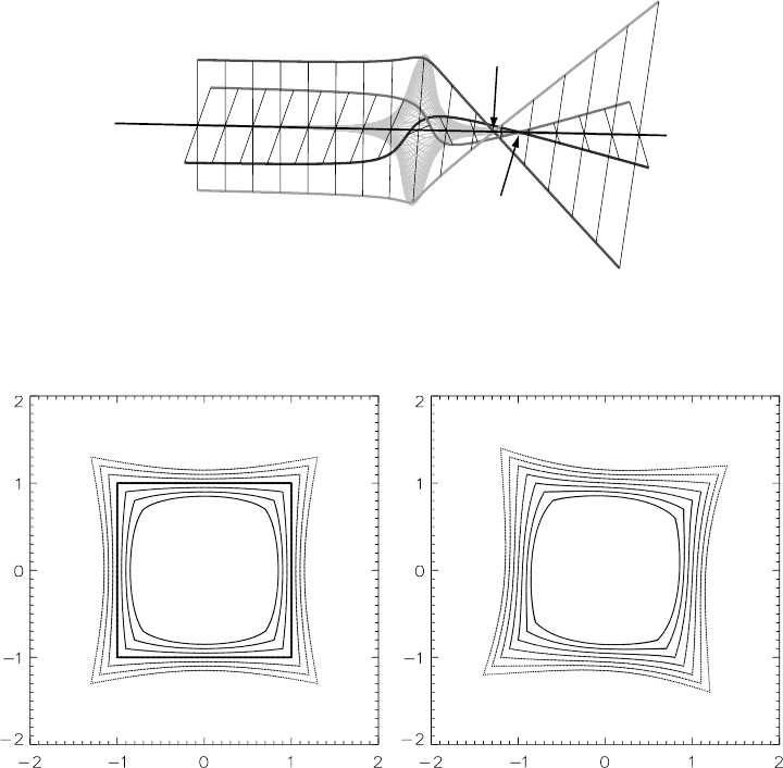
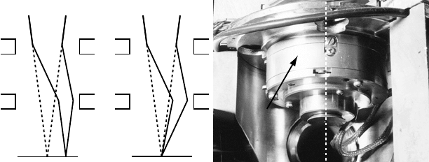
deflectors: beam tilt and beam shift. They are shown schematically in Fig. 3.19
for a converged beam. In the beam shift mode, the first set of deflectors changes
the trajectory without changing the beam shape; the second deflector changes the
(a) (b)
Beam shift Beam tilt
(c)
deflector
optical
axis
Fig. 3.19. Schematic illustration of (a) beam shift mode and (b) beam tilt mode. Part (c) is
a photograph of the beam deflector housing of the JEOL 120CX microscope.
3.6 Basic electron optics: magnetic multipole lenses 177
trajectory by precisely the opposite angle, so that the electron beam is translated
or shifted across the sample. The field of the individual deflector elements is rather
short along the beam path, so that the deflection can be represented as an abrupt
change of direction. In beam tilt mode the second deflector provides a deflec-
tion twice as large as that of the first deflector, so that the illumination spot does
not move. Only the angle between the beam and the optical axis at the illumina-
tion spot changes. The same pair of deflectors can be used for both beam tilt and
beam shift by changing the relative excitations of the various deflector surfaces or
coils. It goes without saying that the deflection system must be properly aligned so
that beam tilt and beam shift can operate independently. Figure 3.19(c) shows the
beam deflector of the JEOL 120CX microscope; the round housing contains the
deflector plates and is located below the condensor stigmator which is shown in
Fig. 3.20(c).
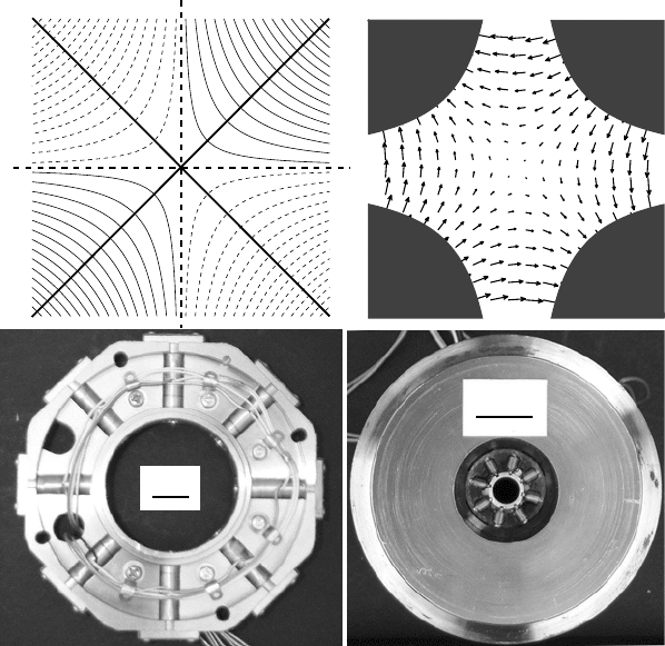
x
y
(a) (b)
1 cm
1 cm
(c)
(d)
Fig. 3.20. (a) Equipotential contours for an ideal quadrupole field with a potential pro-
portional to xy. The symmetry planes are inclined at 45
◦
with respect to the coordinate
axes; (b) magnetic field configuration corresponding to the potential in (a). (c) and (d) are
photographs of the condensor and objective stigmators of the JEOL 120CX microscope,
respectively.