Heinrich J.G., Aldinger F. (Eds.) Ceramic Materials and Components for Engines
Подождите немного. Документ загружается.


This Page Intentionally Left Blank
STEREOLITHOGRAPHY
FOR
CERAMIC PART MANUFACTURING
C. Chaput*,T. Chartier**, F. Doreau*, M. Loiseau*
(*)
CTTC,
Ester Technopole, BP 6915,87069 Limoges, France
(**)
SPCTS, UMR CNRS 6638, ENSCI,
47/73 avenue Albert Thomas, 87065 Limoges, France
,ABSTRACT
The fabrication of a prototype with complex shapes
in ceramics, that are very hard and brittle materials, is
very difficult and costly. In most cases, it is necessary to
develop a mould for casting or injection moulding and
subsequently to finish ceramic pieces by machining.
Rapid prototyping presents a great opportunity to realise
ceramic prototypes. The first step in fabricating ceramic
pieces by stereolithography is to prepare adapted
ceramic suspensions with the appropriate rheological
behaviour.
In
our case, we have developed ceramic
pastes with high viscosity and adapted yield value to
work with a new French
Rp
machine. The main
advantages are the stability of the suspensions, no
relaxation time for the menisci and rapidity to realise
each layer. After fabrication by stereolithography,
ceramic parts
are
debinded and sintered. The obtained
ceramic parts exhibit good mechanical properties,
similar to those obtained by classical ceramic
processing. This technology is very interesting to
manuhcture complex ceramic shapes in a short time
and by reducing costs.
INTRODUCTION
Shaping of complex ceramic parts is performed by
various methods using moulds such as slip. casting,
centrifigal casting, gel casting, direct coagulation
casting or injection moulding.
High
pressure injection
moulding is largely used for industrial production of
ceramic parts (generally small ones) of complex shape
and high dimensional tolerances. One factor limiting a
wider application of high pressure injection moulding is
the high initial tooling cost that makes this technique
not adapted for small
runs
and of course for the
fabrication of prototypes. Over about fifteen years,
many
heform
processing methods
of
3D
ceramic parts
without moulds or tooling have
been
developed, for
instance selective laser sintering,
three
dimensional
printing, fised deposition modelling, laminated object
manufacturing and tape casting techniques.
An
attractive route is to transpose the method of
stereolithography, which is largely
used
for the
fabrication of
three dimensional polymer parts, toward
the process of
3D
ceramic pieces with final properties
(mechanical, thermal, electrical.
..)
close to those
obtained by classical processing techniques
[
1-41.
Stereolithography involves polymerisation of a reactive
system, generally based on acrylate or epoxy
monomers, by a space resolved laser. The main
applications
of
the fabrication, by stereolithography, of
ceramic parts should
be
medical implants, the direct
fabrication of refractory moulds and cores or of
prototypes prior to defining an expensive mould of
injection moulding.
This paper describes the fabrication of complex
alumina parts by stereolithography, removal of the
polymer and sintering. It also gives some characteristics
of the sintered parts, as flexural strength and
dimensional resolution that can
be
reached today.
EXPERIMENTAL PROCEDURE
Starting Materials
The alumina powder used (CT1200SG,
ALCOA,
USA) has a mean particle diameter of 1.5 pm and a
specific area of
3.4
m2.g-'. In order to increase the
ceramic fraction, then to reduce the critical shrinkage
during polymerisation and during sintering, an efficient
dispersant which acts both by electrostatic and steric
repulsion is used. A thickener confers a high yield value
to the paste to prevent settling of particles and to
support the piece during fabrication. The monomer is a
diacrylate
(HDDA,
UCB, Belgium). The photoinitiator
absorbs in the range of the
UV
laser emission (Irgacure
65
1,
Ciba, Switzerland).
Preparation
of
the Suspensions
The photoinitiator
(0.5
%
by weight of monomer),
the dispersant (2
%
by weight of powder) and the
thickener
(0.5
%
by weight of monomer) are first
dissolved in the diacrylate, then the alumina powder is
added. The suspension containing 62 vol
Yo
alumina, is
milled during
30
min to break down the agglomerates
and to achieve a good homogeneity.
Fabrication
of
Green Ceramic Pieces by
Stereolithography
Homogeneous layers, with different thickness (from
25 to
100
pm),
with smooth surfaces are spread by
means of a specific device before polymerisation.
Contrary to classical stereolithography equipment,
where a fluid monomer is required, our machine uses a
353
paste with a high viscosity, thus avoiding the use of a
container.
Using CAD information, laser
beam
radiation
(Ar-
ion laser, Coherent,
h
=
351-364
nm),
focused
on
the
top surface of the deposited paste, is deflected by
galvanometric mirrors. When a layer of the part
is
performed, the deposition of a subsequent layer of paste
on the already polymerised part allows to continue the
manufacturing process. This procedure is repeated until
the polymer part is built.
Binder Removal and Sintering
Based on thermogravimetric analysis of green
samples, the debinding is performed with a heating rate
of 1"C.min-' up to 120°C, then of 0.2"C.min-' up to
550°C with a stage of 3 h. The polymeric phase is then
completely removed. The parts are finally sintered with
a heating rate of 5"C.min-I up to
1700°C
with a 1.5 h
plateau. The density of sintered pieces is
97%
of the
theoretical density.
Characterization
Rheological measurements are performed with a
controlled stress rheometer
(RS150,
HAAKE,
Germany) using a cone-plane configuration.
The reactive system has to verig two main
requirements, i) the cured depth must
be
high enough to
avoid an excessive time of fabrication and, ii) the cured
width must be low enough to ensure a good resolution.
In
this respect, cured depth and width are measured
on
small polymerised lines cured in one layer by one
scanning of the laser
beam.
The brittle polymerised
lines are included in an epoxy resin in order to cut
sections for observation. The values of depth and width
correspond to the average
of
four measurements.
The flexural strength of as-sintered and polished
alumina bars (3.5~5.5~40 mm3), fabricated under
similar
UV
exposure conditions but with six different
scanning patterns is measured by threepoint bend tests
(average of five values). Two loading directions, with
respect to layer planes, are also tested. These values are
compared to flexural strength of the same alumina
pressed samples sintered in the same conditions.
RESULTS AND DISCUSSION
The
Paste
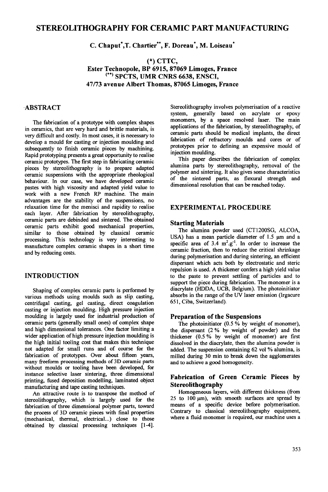
A rheological behaviour adapted to the principle of
the specific stereolithography technique used is
required. The flow curve exhibits a typical shear
thinning behaviour (Fig. 1). The high yield value (1200
Pa) allows to prevent non-insulated surfaces fiom
flowing during the building of the piece and then to
support it. The shear thinning behaviour allows
spreading of homogeneous layers with a thickness
ranging fiom 25 to 200 pm. At a shear rate of 100
s-',
corresponding to the minimum value generated by the
machine during layer deposition, the measured viscosity
is
110 Pas, compared to 12000 Pas at rest.
.t
F1
9
[Pa4
14ooo
3500
P
2000
1500
500
0
20
40
60
80
100 120 140
r
1s-l
I
Fig.
1
:
Suitable rheological behaviour of the ceramic
paste
Depth and Width
of
Photopolymerisation
A first objective is to reduce the time of fabrication
of pieces, then to use a high scanning speed while
maintaining a sufficient cured depth. The cured depth
(Ep) depends on the density of energy (DE) transmitted
to the paste, on the depth of penetration of the
beam
(Dp),
characteristic of the paste (particle diameter,
volume fiaction of powder, difference between the
refiactive index of the powder and of the resin
.
.
.)
and
on the critical density of energy (DEc) that represents
the smallest DE for which polymerisation
OCCUTS
[5-71:
Ep
=
Dp
In(-)
The density of energy DE is function of the power of
irradiation
P,
of the scanning speed v and of the
diameter of the laser spot wo
(80
pm) on the working
SUrface:
Eq.
1
DE
DEc
Eq.
2
2 .P
DE=-
5c.w .v
It has
been
shown that the depth of polymerisation does
not vary with P/v ratio at constant density of energy,
in
agreement with equations 1 and 2. We can also notice
that a cured depth of 200 pm can be achieved using a
high scanning speed (1 m.d, DE
FZ
0.3
J.cm-')
for a
concentrated system (62 vol
%
alumina).
A second objective is to obtain a good dimensional
resolution, then to control the width
of
polymerisation.
The width
of
polymerisation could be greatly affected
by scattering phenomena due to the presence of ceramic
particles and could
be
significantly larger than the
beam
diameter. The classical theories of scattering (Rayleigh,
Gans, Mie) are verified for diluted systems (<lo vol%),
but they cannot
be
applied to concentrated systems.
The evolution of the cured width in function of the
density of energy for different natures of powder is
given in Fig. 2. The width of polymerisation is always
larger than the laser
beam
diameter, confirming
scattering phenomena, and logarithmic behaviour of
cured depth and width is observed whatever is the
nature of the powder. A high cured depth requires a
354
high density of energy whereas a high resolution
requires a low density of energy, then a compromise has
-
0.6
-
5
$
0.4
-
U
-
'0
f
0.2
-
0
to
be
found, in particular for the scanning conditions of
external surfaces of the pieces.
R2
=
0.9868
R2
=
0.9947
R2
=
0.9983
gfs
Osilica
d50=10pm Palumina d50=5pm
alumina d50=0.5pm
szirconia
d50=1Opm
R2
=
0.9989
1.8
1
-
E
1.5
-
E
-
1.2
-
5
g
2
0.3
-
p
0.9
-
0.6
-
,9855
,9938
.9813
01
DE=80
mJ/cm2
I
DE40
mJ/cm2
0 2
4
6
DE
(Jlcm2)
DE=30
mJ/cm2
0
Silica
d50=1Opm
Q
alumina d50=5pm
alumina d50=0.5pm
0
zirconia d50=10pm
0.8
i
R2
=
0.9793
04
0
2
4
6
DE
(Jlcm2)
Fig. 2
:
Cured
depth and width according to density of energy DE for various powders (50%~)
In
comparison with these results, the limit dimensional
resolution
of
our
system has
been
studied, by varying
the scanning speed and the layer depth. Two scanning
patterns have been tested
:
one with simple lines parallel
to the spread axis
(X),
and a second representing a mesh
(parallel and perpendicular
(Y)
to
X
)
of
1
and
2
mm.
Fig. 3 shows the results obtained with the simple lines
for
10
layers of 25pm depth.
A
limit resolution of
170pm can
be
reached for simple lines.
1 mm
I I
230
pm
420
pm
I
Honey comb (2mm mesh)
Honey comb
(1
mm mesh)
I
Layer depth 25~, 20 layers.
I
Layer depth 25pm,
120
layers.
DE=50
mJ.cm-*
DE=160
mJ.cm-*
Fig.
4
:
Honey
comb parts for different densities
of
energy and mesh dimensions
355
Mechanical Characterization
of
Flexural
Strength
No
significant differences in flexural strength are
observed
between
the different layer orientations
or
scanning patterns
used,
attesting of a good
homogeneity.
An
average value of 275 MPa
is
obtained
for as-sintered samples, which is similar to that of
pressed specimens
(265
ma).
When
bars
are polished
before testing, an average value of
394
MPa
is obtained
for rapid prototyped specimens and
396
MPa for
pressed specimens. It is then possible to fabricate
complex shape parts by stereolithography with similar
mechanical properties than those obtained by classical
shaping process like uniaxial pressing.
Sintered Ceramic Parts Obtained by
S
tereolithography
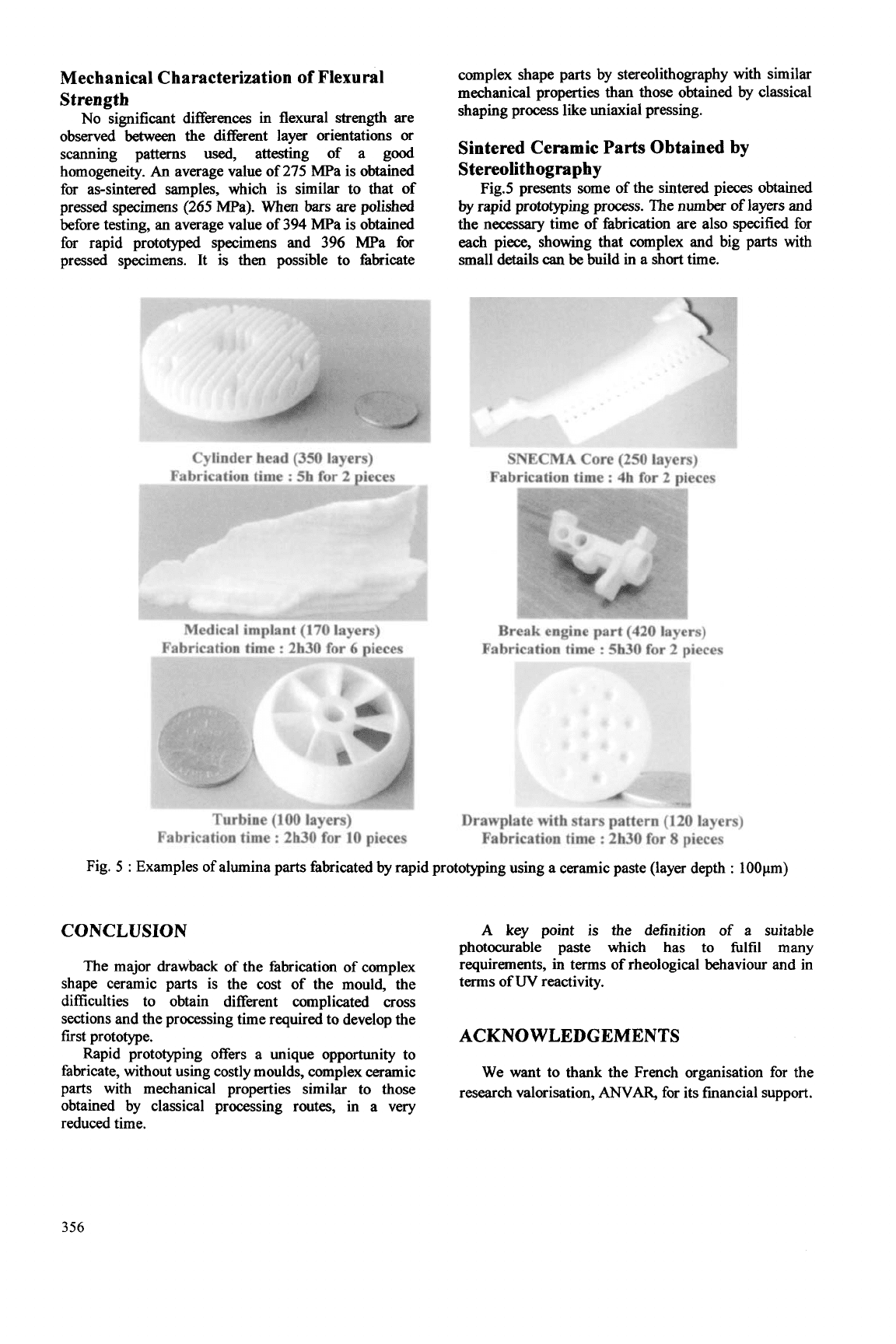
Fig.5 presents some of the sintered pieces obtained
by rapid prototyping process. The number
of
layers and
the necessary time of fabrication are also specified for
each piece, showing that complex and big parts with
small details can
be
build in a short time.
Cylinder
head
(350
layers)
Fabrication
time
:
5h
for-2
~ieces
Turbine
(100
layers)
Fabrication time
:
2h30 for
10
pieces
Fig.
5
:
Examples of alumina parts fabricated by rapid pr
CONCLUSION
The major drawback of the fabrication of complex
shape ceramic parts is the cost of the mould, the
difficulties to obtain different complicated
cross
sections and the processing time required to develop the
first prototype.
Rapid prototyping offers a unique opportunity to
fabricate, without using costly moulds, complex ceramic
parts with mechanical properties similar to those
obtained by classical processing routes, in a very
reduced time.
SNECMA
Core
(250
layers)
Break engine
part
(420 layers)
Fabrication time
:
5h30
for
2
pieces
Drawplate
with
stars
pattern (120 layers)
Fabrication time
:
2h30 for
8
pieces
,ototyping using a ceramic paste (layer depth
:
100pm)
A
key point is
the
definition of a suitable
photocurable paste which has
to
fulfil
many
requirements,
in
terms of rheological behaviour and
in
terms of
W
reactivity.
ACKNOWLEDGEMENTS
We want to thank the French organisation for the
research valorisation,
MAR,
for its financial support.
356
REFERENCES
[
13
C. Hinczewski,
S.
Corbel and
T.
Chartier, "Ceramic
suspensions suitable for stereolithography,"
Journal
of
the European Ceramic Society, 18 (1998),
pp.
583-90.
[2]
C. Hinczewski,
S.
Corbel and T. Chartier,
"Stereolithography for the fabrication of ceramic three-
dimensional parts,"
Journal of Rapid Prototyping., 4
[3]
[3]
M.L. Griffith
and
J.W. Halloran, "Freeform
fabrication
of
ceramics via stereolithography,"
Journal
of the American Ceramic Society, 79
[lo]
(1996),
pp.
[4]
H.Liao and T.W. Coyle, "Photoreactive suspensions
for
stereolithography of ceramics,
"
Journal of the
Canadian Ceramic Society, 65 [4] (1 996),
pp.
254-262.
[5]
Brady G.A., Chu T.M., Halloran J.W, "Curing
behavior
of
ceramic resin for stereolithography",
Proceedings of the Solid Freeform Fabrication
Symposium,
University of Texas, Austin, p.
403-4 10,
1996.
[6]
Grifith M.L., Chu T.M., Wagner W.C., Halloran
J. W., "Ceramic stereolithography for investment casting
and biomedical applications",
Proceedings of the Solid
Freeform Fabrication Symposium,
University of Texas,
Austin, p.
31-38, 1995.
[7]
Hinczewski, "Stereolithographie pour la fabrication
de ckramiques", PhD Thesis, Institut National
Polytechnique de Lorraine, October
1998.
(1998),
pp.
104-
1
1.
2601-08.
357

This Page Intentionally Left Blank
APPLICATION OF THE MOLD SDM PROCESS TO
THE FABRICATION OF CERAMIC PARTS FOR A MICRO GAS TURBINE
ENGINE
Sangkyun Kang*, Jurgen Stampfl, Alexander
G.
Cooper and Fritz
B.
Prinz
Stanford University, Stanford, CA
94305-3030,
USA
Abstract
A micro gas turbine engine with silicon nitride
parts is being developed. In this project, the Mold
Shape Deposition Manufacturing (Mold SDM) process
is used to fabricate high quality ceramic parts with
complex shapes such as the rotor group.
The merits of micro gas turbine engines in general
are described before focusing on processing and fabri-
cation issues. The obtained silicon nitride parts are
characterized concerning their mechanical and micro-
structural properties. The surface roughness, shrinkage
during sintering, final density and achievable feature
sizes have been determined. Using Mold SDM a func-
tional rotor group has been successfully fabricated.
456,000
rpm rotational speed has been acheved during
the spin tests at room temperature with nitrogen as
driving gas.
INTRODUCTION
Micro gas turbine engine
A micro gas turbine engine with silicon nitride
parts is being developed by the Rapid Prototyping
Laboratory (RPL) of Stanford University and its
in-
dustrial partners. The engine is designed by M-DOT
Aerospace (Arizona, USA) and the RPL is responsible
for the manufacturing and materials processing of the
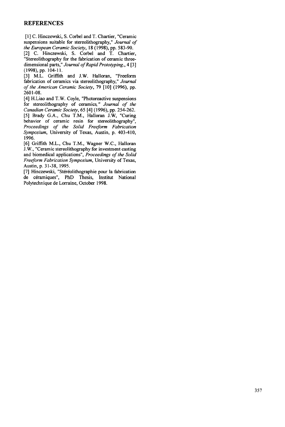
silicon nitride parts. Figure
1
shows the original design
of the micro gas turbine engine developed by M-DOT.
This one is similar to current engine but it does not use
ceramic parts. This type of engine can be used as a
portable energy source or in small flying vehicles.
Figure
1
M-DOT
micro gas turbine engine.
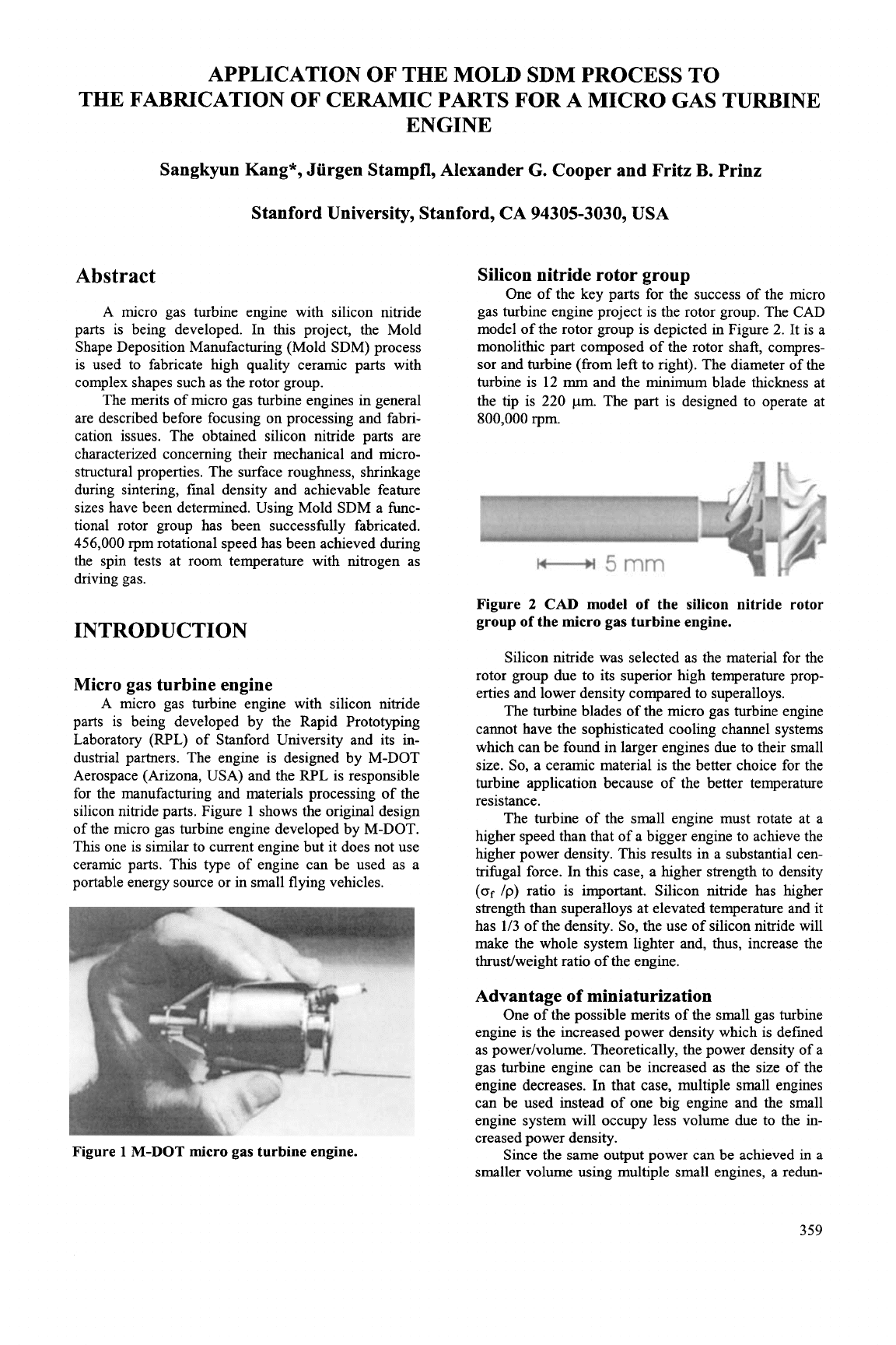
Silicon nitride rotor group
One of the key parts for the success of the micro
gas turbine engine project is the rotor group. The CAD
model of the rotor group is depicted in Figure
2.
It is a
monolithic part composed of the rotor shaft, compres-
sor and turbine (from left to right). The diameter of the
turbine is
12
rnm
and the minimum blade thickness at
the tip is
220
pm. The part is designed to operate at
800,000
rpm.
Figure
2
CAD
model
of
the silicon nitride rotor
group
of
the micro gas turbine engine.
Silicon nitride was selected as the material for the
rotor group due to its superior high temperature prop-
erties and lower density compared to superalloys.
The turbine blades of the micro gas turbine engine
cannot have the sophisticated cooling channel systems
which can be found in larger engines due to their small
size.
So,
a ceramic material is the better choice for the
turbine application because of the better temperature
resistance.
The turbine of the small engine must rotate at a
higher speed than that of a bigger engine to achieve the
higher power density. This results in a substantial cen-
trifugal force. In this case, a higher strength to density
(of
/p)
ratio is important. Silicon nitride has higher
strength than superalloys at elevated temperature and it
has
1/3
of the density.
So,
the use of silicon nitride will
make the whole system lighter and, thus, increase the
thrust/weight ratio of the engine.
Advantage
of
miniaturization
One of the possible merits of the small gas turbine
engine
is
the increased power density which is defined
as power/volume. Theoretically, the power density of a
gas turbine engine can be increased as the size of the
engine decreases. In that case, multiple small engines
can be used instead of one big engine and the small
engine system will occupy less volume due to the in-
creased power density.
Since the same output power can be achieved in
a
smaller volume using multiple small engines, a redun-
359
dant system can be implemented by adding more en-
gines into the saved volume. A redundant system can
have higher reliability. Figure
3
illustrates a redundant
system. It was assumed that 16 small engines in the
right system will generate the same power as the one
big engine on the left. In
this
case, four engines are
redundant.
Single engine Redundant system
system
(20
small engines)
Figure
3
Single engine system and redundant sys-
tem. In this system,
16
small engines are necessary
to produce the same amount of power as the large
engine.
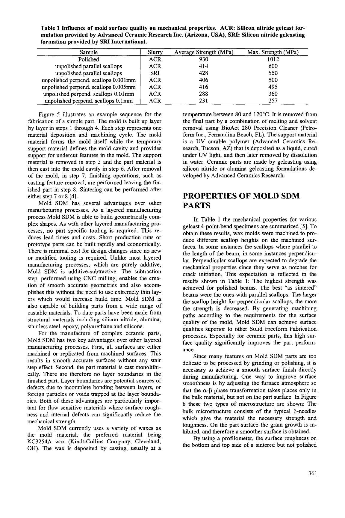
Simple calculation of the probability of failure
based on binomial distribution shows the higher reli-
ability of the redundant system. (The formulation is in
Appendix) Figure
4
compares the failure probability of
one big engine and the redundant system illustrated in
Figure 3. According to the computational result, as-
suming the failure probability of each engine is 2x10-*,
the failure probability is 2~10-~ for one engine but
3.8~10-~ for the redundant system.
Pfs
1
.E-2
1
.E-5
1
.E-8
1
F-I1
Pf
1
..
0.001
0.01 0.1
Figure
4
The failure probability comparison
of
one
big engine (dotted black line) and
20
small engines
(solid line) system.
Pn:
failure probability of each
engine,
Pfs:
failure probability
of
20
engine system.
The probability of failure of a large ceramic
specimen is greater than a small ceramic specimen
under the same stress and the Weibull treatment of
failure incorporates this relation [l].
So,
in
terms of
reliability, the application of ceramic parts in a small
gas turbine engine is more beneficial than a large en-
gine.
The volumetric relation of the reliability of the ce-
ramic parts can be combined with the reliability of the
redundant system. The failure probability of each small
engine that has ceramic parts in it will decrease due to
the reduced failure probability of the ceramic parts.
This will reduce the
Pfl
value of each small engine in
Figure
4.
Therefore, fiuther improvement of the reli-
ability can be achieved form the miniaturization.
Manufacturing process for the silicon ni-
tride rotor group
The silicon nitride rotor group (Figure 2) has a
complex shape. Design iterations are anticipated during
the progress of the project.
So,
the ability to fabricate
high quality ceramic parts quickly is required.
The surface quality of the rotor is important be-
cause the strength
of
ceramic parts is hghly dependent
on the surface condition. It must also be noted that the
rotor geometry does not allow postprocessing, such as
grinding, due to its shape complexity.
A manufacturing process that can produce a ce-
ramic part with complex shape and good surface finish
is required for
this
project.
In terms of shape complexity, commercial rapid
prototyping techniques are good candidate processes
for the manufacturing
of
the rotor group. However, the
surface quality of rapid prototyped parts is limited due
to the stair step effect. The rough surfaces become
good crack initiation site and
thls
reduces the strength
of the parts significantly. The surface quality can be
improved by reducing the layer thickness but the im-
provement is linear, which means the stair step is
halved as the thickness of the layer
is
halved
[2].
The traditional ceramic fabrication processes, such
as machining of green ceramic blanks, have limitations
in achievable shape complexity due to the tool access
constraint. However, machining can produce parts with
good surface quality and the surface quality improves
rapidly. For example, in ball endmill machining, if the
space between two machining paths become 112, the
scallop height reduces to
114
due to the quadratic con-
vergence property of machining [2].
MOLD SHAPE DEPOSITION
MANUFACTURING (MOLD SDM)
Mold Shape Deposition Manufacturing (Mold
SDM) is a manufacturing process that can be used to
build ceramic, metal and polymer parts. Mold SDM is
a
two
step process. Fugitive wax molds are first built
using an additive-subtractive layered manufacturing
process. Then a variety of castable materials, including
ceramic and metal gelcasting slurries as well as casta-
ble thermoset polymers, can be cast into these molds to
produce parts
[3].
I..
5
6
7
0
Figure
5
Mold
SDM
procedures.
360
Sample
Polished
unpolished parallel scallops
unpolished parallel scallops
unpolished perpend. scallops 0.001mm
unpolished perpend. scallops 0.0lmm
unpolished perpend. scallops
0.
lmm
unpolished perpend. scallops
0.005mm
Figure 5 illustrates an example sequence for the
fabrication of a simple part. The mold is built up layer
by layer in steps 1 through 4. Each step represents one
material deposition and machining cycle. The mold
material forms the mold itself while the temporary
support material defines the mold cavity and provides
support for undercut features in the mold. The support
material is removed in step
5
and the part material is
then cast into the mold cavity in step
6.
After removal
of the mold, in step 7, finishing operations, such as
casting feature removal, are performed leaving the fin-
ished part in step 8. Sintering can be performed after
either step 7 or 8 [4].
Mold SDM has several advantages over other
manufacturing processes. As a layered manufacturing
process Mold SDM is able to build geometrically com-
plex shapes. As with other layered manufacturing pro-
cesses,
no
part specific tooling is required. This re-
duces lead times and costs. Short production runs or
prototype parts can be built rapidly and economically.
There is minimal cost for design changes since no new
or modified tooling is required. Unlike most layered
manufacturing processes, which are purely additive,
Mold SDM is additive-subtractive. The subtraction
step, performed using CNC milling, enables the crea-
tion of smooth accurate geometries and also accom-
plishes this without the need to use extremely thin lay-
ers which would increase build time. Mold SDM is
also capable of building parts from a wide range
of
castable materials. To date parts have been made from
structural materials including silicon nitride, alumina,
stainless steel, epoxy, polyurethane and silicone.
For the manufacture of complex ceramic parts,
Mold SDM has two key advantages over other layered
manufacturing processes. First, all surfaces are either
machined or replicated from machined surfaces. This
results in smooth accurate surfaces without any stair
step effect. Second, the part material is cast monolithi-
cally. There are therefore no layer boundaries in the
finished part. Layer boundaries are potential sources
of
defects due to incomplete bonding between layers, or
foreign particles or voids trapped at the layer bounda-
ries. Both of these advantages are particularly impor-
tant for flaw sensitive materials where surface rough-
ness and internal defects can significantly reduce the
mechanical strength.
Mold SDM currently uses a variety of waxes as
the mold material, the preferred material being
KC3254A wax (Kindt-Collins Company, Cleveland,
OH).
The wax is deposited by casting, usually at a
Slurry Average Strength (MPa) Max. Strength (MPa)
ACR 930 1012
ACR 414
600
SRI
428
550
ACR 406
500
ACR 416 495
ACR 288
3
60
ACR 23 1 257
temperature between 80 and 120OC. It is removed from
the final part by a combination of melting and solvent
removal using BioAct 280 Precision Cleaner (Petro-
ferm Inc., Fernandina Beach, FL). The support material
is a
W
curable polymer (Advanced Ceramics Re-
search, Tucson,
AZ)
that
is
deposited as a liquid, cured
under
UV
light, and then later removed by dissolution
in water. Ceramic parts are made by gelcasting using
silicon nitride or alumina gelcasting formulations de-
veloped by Advanced Ceramics Research.
PROPERTIES
OF
MOLD
SDM
PARTS
In Table 1 the mechanical properties for various
gelcast 4-point-bend specimens are summarized
[S].
To
obtain these results, wax molds were machined to pro-
duce different scallop heights on the machined sur-
faces.
In
some instances the scallops where parallel to
the length of the beam, in some instances perpendicu-
lar. Perpendicular scallops are expected to degrade the
mechanical properties since they serve as notches for
crack initiation.
This
expectation is reflected in the
results shown in Table
1:
The highest strength was
achieved for polished beams. The best “as sintered”
beams were the ones with parallel scallops. The larger
the scallop height for perpendicular scallops, the more
the strength is decreased. By generating machining
paths according to the requirements for the surface
quality
of
the mold, Mold SDM can achieve surface
qualities superior to other Solid Freeform Fabrication
processes. Especially for ceramic parts, this high sur-
face quality significantly improves the part perform-
ance.
Since many features on Mold SDM parts are too
delicate to be processed by grinding or polishing, it is
necessary to achieve a smooth surface finish directly
during manufacturing. One way to improve surface
smoothness is by adjusting the furnace atmosphere so
that the
a-p
phase transformation takes places only in
the bulk material, but not on the part surface. In Figure
6
these two types of microstructure are shown: The
bulk microstructure consists of the typical P-needles
which give the material the necessary strength and
toughness. On the part surface the grain growth is in-
hibited, and therefore a smoother surface is obtained.
By using a profilometer, the surface roughness on
the bottom and top side of a sintered but not polished
361