Inversin R. Allen Micro-hydropower Sourcebook
Подождите немного. Документ загружается.

log gate permits the forebay to be drained so that sedi-
ment can be cleared or repairs made. Because the
trashrack is located below the surface of the water,
much of the surface debris is not caught. The spillway
is strategically placed so that excess, overflowing water
continuously sweeps floating debris out of the forebay.
Less frequent cleaning of the trashrack is therefore
necessary. Just before the trashrack, stoplogs can be
inserted to prevent flow into the penstock when this is
necessary.
The design shows a vent incorporated in the
wall of the forebay; however, this vent is frequently
installed at the upper end of the penstock pipe itself
(see Fig. 5.21).
To reduce turbulence and losses, the penstock inlet of
large hydropower schemes is generally bell-shaped.
However, for many micro-hydropower plants, the pen-
stock inlet is simply a portion of the pipe extending
through, or flush with, the forebay wall. Even for these
configurations, the losses incurred are *usually minimal.
The head loss coefficient “K ” associated with various
pipe entrances is illustrated ?n Fig. 5.128. The actual
head loss is found by using the following equation:
he= K
V2
e2g
(5.10)
where “v” is the velocity in the penstock. By incorpo-
rating a proper bell-shaped rather than a square-edged
entry, head losses at the inlet are significantly reduced.
But for penstock velocities even as high as 2 m/s, these
losses amount to only 0.1 m. Consequently, these losses
are generally insignificant, and only for very low-head
sites should an effort be made to incorporate a proper
bell-shaped entry. Even slightly rounding the entrance
reduces head loss by at least 50%. Although a hooded
inlet increases losses slightly, it makes it more difficult
for passersby to drop small stones into the penstock.
A vortex which forms at the inlet to the penstock occa-
sionally can cause troubles. It can induce loss of turbine
efficiency, possible cavitation, surging caused by the
formation and dissipation of vortices, and flow reduc-
tion as air replaces part of the water through the inlet.
It can also draw floating debris into the penstock.
Most research on the formation of vortices has involved
hydraulic model studies of specific sites. These are
appropriate for large hydropower schemes, but those
implementing micro-hydropower plants cannot afford
the cost and delays associated with such studies. Design
criteria to prevent vortex formation are needed, but
little has been done in this area.
Designing for a low velocity into the penstock and
increasing submergence of the inlet can help prevent
the formation of vortices. Also, a vertical inlet has a
greater tendency for vortex formation than a horizontal
one. Whereas these parameters are easy to quantify,
vortex formation also seems to depend considerably on
the circulation (swirl) in the water as it approaches the
inlet. This circulation is primarily a function of the
configuration of the area just upstream of the intake
and can be caused by canal irregularities or separation
of fiow at the edge of a canal or forebay wall. Flow
120 Civil works
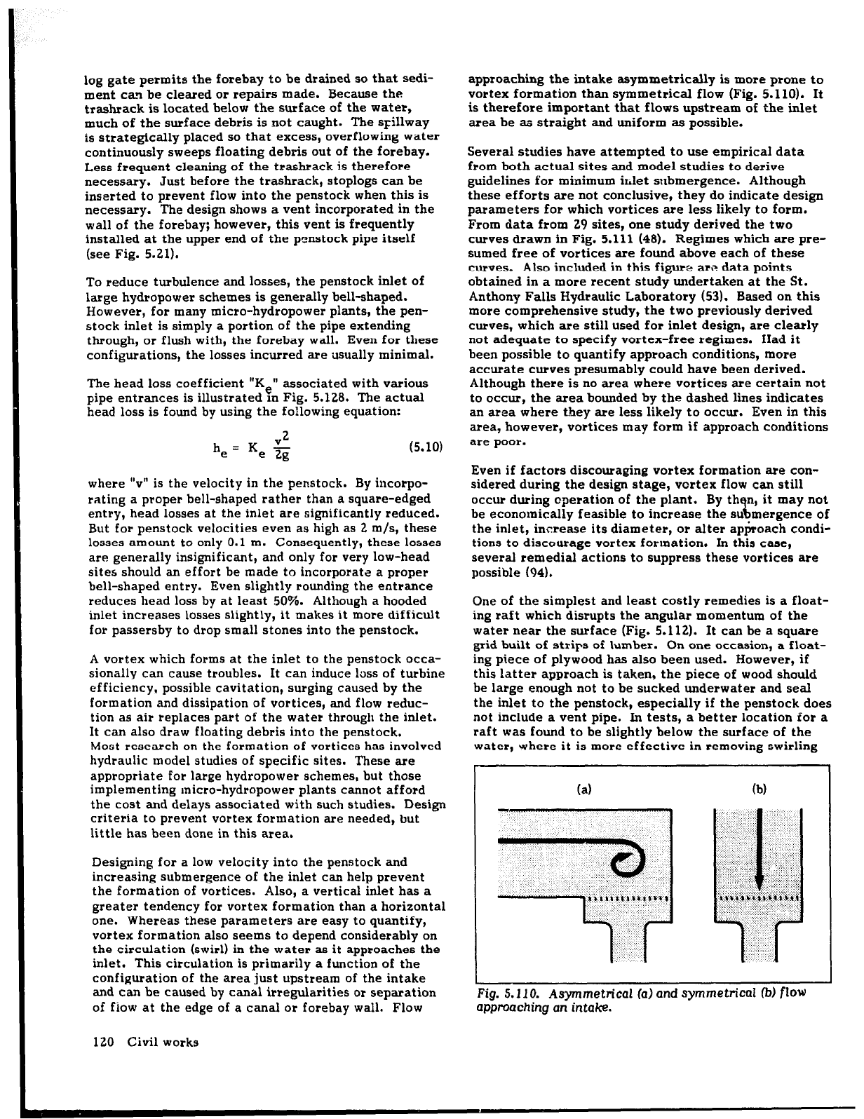
approaching the intake asymmetrically is more prone to
vortex formation than symmetrical flow (Fig. 5.110). It
is therefore important that flows upstream of the inlet
area be as straight and uniform as possible.
Several studies have attempted to use empirical data
from both actual sites and model studies to derive
guidelines for minimum inlet submergence. Although
these efforts are not conclusive, they do indicate design
parameters for which vortices are less likely to form.
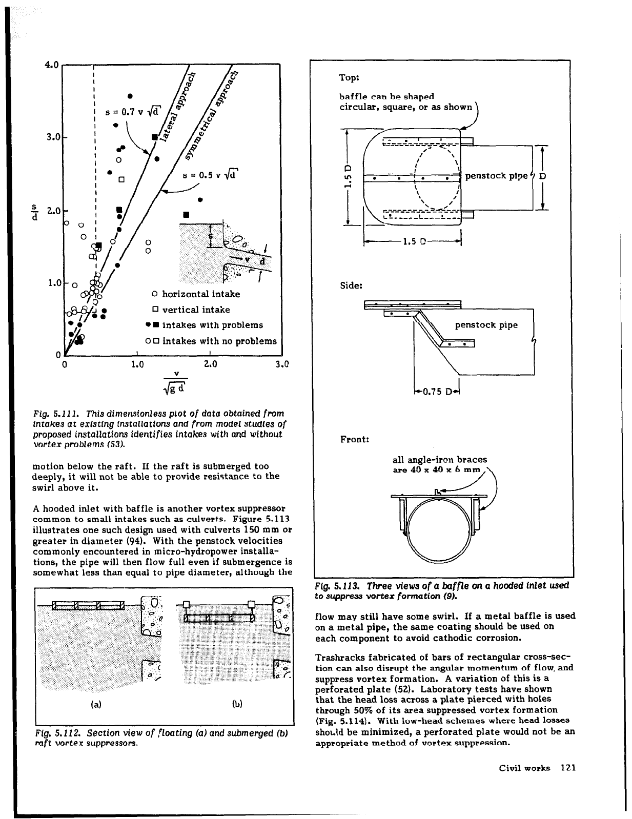
From data from 29 sites, one study derived the two
curves drawn in Fig. 5.111 (48). Regimes which are pre-
sumed free of vortices are found above each of these
curves. Also included in this figure are data points
obtained in a
more
recent study undertaken at the St.
Anthony Falls Hydraulic Laboratory (53). Based on this
more comprehensive study, the two previously derived
curves, which are still used for inlet design, are clearly
not adequate to specify vortex-free regimes. Had it
been possible to quantify approach conditions, more
accurate curves presumably could have been derived.
Although there is no area where vortices are certain not
to occur, the area bounded by the dashed lies indicates
an area where they are less likely to occur. Even in this
area, however, vortices may form if approach conditions
are poor.
Even if factors discouraging vortex formation are con-
sidered during the design stage, vortex flow can still
occur during operation of the plant. By th n, it may not
% be economically feasible to increase the su mergence of
the inlet, increase its diameter, or alter ap$roach condi-
tions to discourage vortex formation. In this case,
several remedial actions to suppress these vortices are
possible (94).
One of the simplest and least costly remedies is a float-
ing raft which disrupts the angular momentum of the
water near the surface (Fig. 5.112). It can be a square
grid built of strips of lumber. On one occasion, a float-
ing piece of plywood has also been used. However, if
this latter approach is taken, the piece of wood should
be large enough not to be sucked underwater and seal
the inlet to the penstock, especially if the penstock does
not include a vent pipe. In tests, a better location for a
raft was found to be slightly below the surface of the
water, Yrhere it is more effective in removing swirling
(a) 04
Fig.
5.110. Asymmetrical la)
and
symmetrical fb)
flow
approaching an intake.
3.a
+
2.c
1s
C
0 horizontal intake
0 vertical intake
l n
intakes with problems
o 0 intakes with no problems
I
I
1.0
2.0
3.0
V
Fig. 5.111.
This
dimensionless
plot of data obtained from
intakes
at
existing installations and from
model
studies
of
proposed installations identifies
intakes
with and without
vortex problems (53).
motion below the raft. If the raft is submerged too
deeply, it will not be able to provide resistance to the
swirl above it.
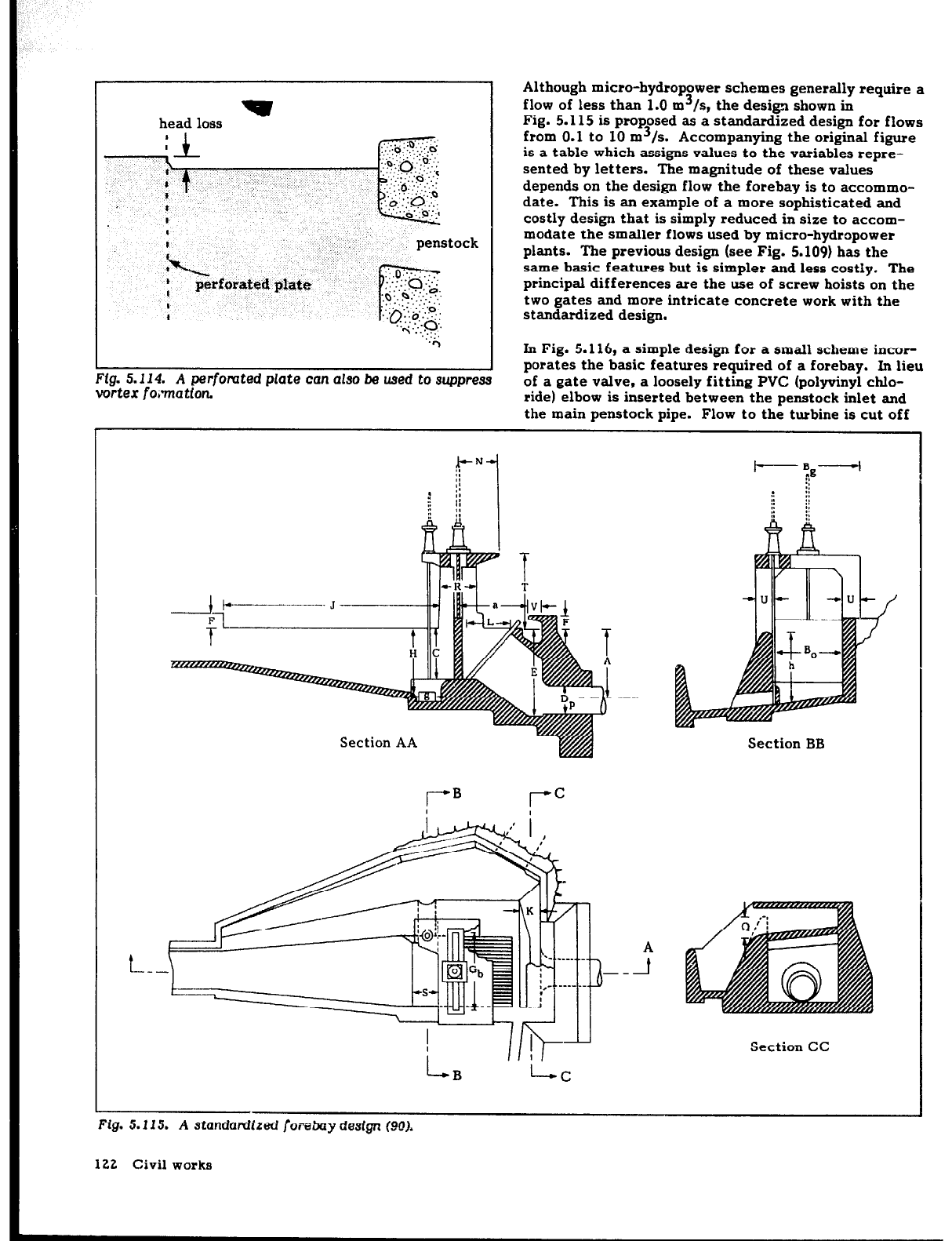
A hooded inlet with baffle is another vortex suppressor
common to small intakes such as culverts. Figure 5.113
illustrates one such design used with culverts 150 mm or
greater in diameter (94). With the penstock velocities
commonly encountered in micro-hydropower installa-
tions, the pipe will then flow full even if submergence is
somewhat less than equal to pipe diameter, although the
(a)
b)
Fig.
5.112. Section view of floating (a) and
submerged (b)
raft vortex suppressors.
Top:
baffle can be shaped
circular, square, or as shown
Side:
-
=
=
4
penstock pipe
Fzl
. .
co.75 D
+I
Front:
all angle-iron braces
are40x40xbmm,\
Fig.
5.113. Three views of
a baffle on a hooded
Met usea
to Suppress vortex formation (9).
flow may still have some swirl. If a metal baffle is used
on a metal pipe, the same coating should be used on
each component to avoid cathodic corrosion.
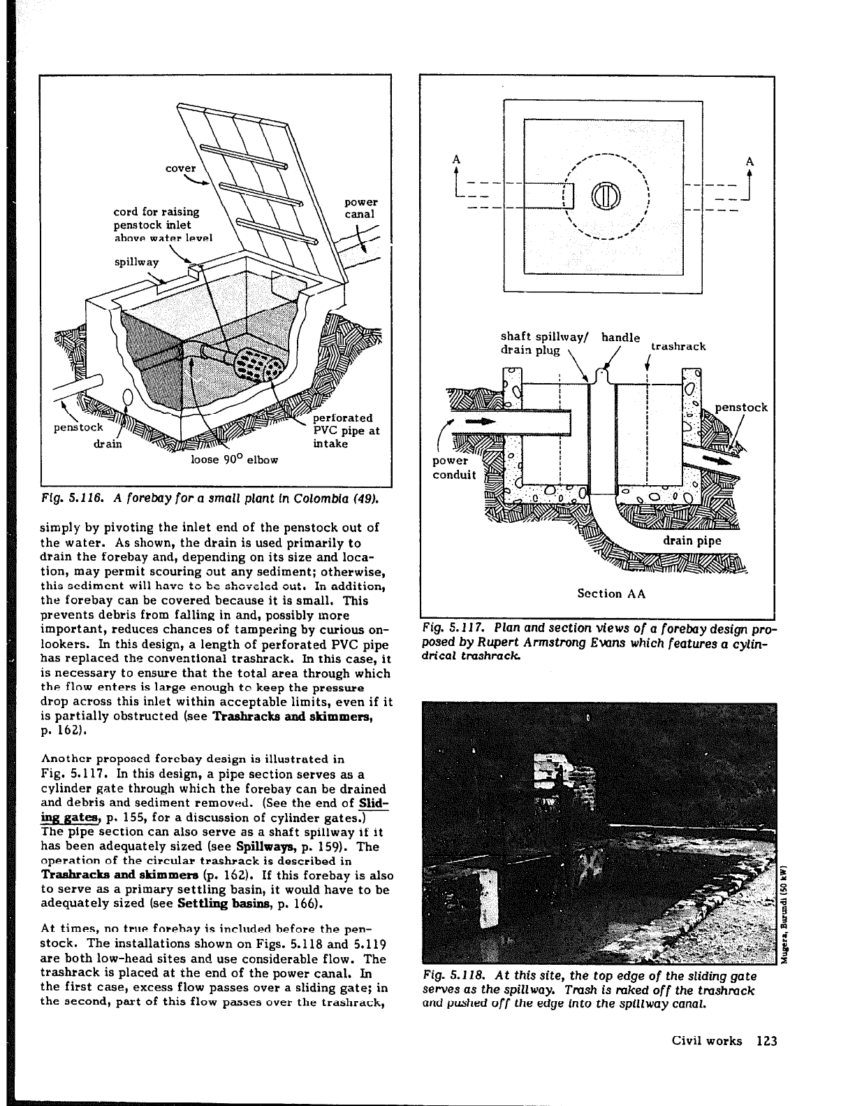
Trashracks fabricated of bars of rectangular cross-sec-
tion can also disrupt the angular momentum of flow, and
suppress vortex formation. A variation of this is a
perforated plate (52). Laboratory tests have shown
that the head loss across a plate pierced with holes
through 50% of its area suppressed vortex formation
(Fig. 5.114). With low-head schemes where head losses
should be minimized, a perforated plate would not be an
appropriate method of vortex suppression.
Civil works 121
w
head loss
it
Lock
Ffg. 5.114. A perfomted plate
can also be used to suppress
vortex
fonnatfon
In Fig. 5.116, a simple design for a small scheme incor-
porates the basic features required
of
a forebay. In lieu
of a gate valve, a loosely fitting PVC (polyvinyl chlo-
ride) elbow is inserted between the penstock inlet and
the main penstock pipe. Flow to the turbine is cut off
Although micro-hydropower schemes generally require a
flow of less than 1.0 m3/s, the design shown in
Fig. 5.115 is proposed as a standardized design for flows
from 0.1 to 10 m3/s. Accompanying the original figure
is a table which assigns values to the variables repre-
sented by letters. The magnitude of these values
depends on the design flow the forebay is to accommo-
date. This is an example of a more sophisticated and
costly design that is simply reduced in size to accom-
modate the smaller flows used by micro-hydropower
plants. The previous design (see Fig. 5.109) has the
same basic features but is simpler and less costly. The
principal differences are the use of screw hoists on the
two gates and more intricate concrete work with the
standardized design.
Section AA
Section BB
Section CC
Fig. 5.115. A
standardized
fore&y design (VOO).
122 Civil works
LYTLA cover
cord for raising
penstock inlet
above water level
spillway
drain *
“‘IF-
\ \\ canal
loose 90° elbow
Fig. 5.116.
A
forebay
for a small plant
In
Colombia (49).
simply by pivoting the inlet end of the penstock out of
the water. As shown, the drain is used primarily to
drain the forebay and, depending on its size and loca-
tion, may permit scouring out any sediment; otherwise,
this sediment will have to be shoveled out. In addition,
the forebay can be covered because it is small. This
prevents debris from falling in and, possibly more
important, reduces chances of tampering by curious on-
lookers. In this design, a length of perforated PVC pipe
has replaced the conventional trashrack. In this case, it
is necessary to ensure that the total area through which
the flow enters is large enough tc keep the pressure
drop across this inlet within acceptable limits, even if it
is partially obstructed (see Trashracks and skimmers,
p. 162).
Another proposed forebay design is illustrated in
Fig. 5.117. In this design, a pipe section serves as a
cylinder gate through which the forebay can be drained
and debris and sediment removed. (See the end of Slid-
mg gatea, p. 155, for a discussion of cylinder gates.)
The pipe section can also serve as a shaft spillway if it
has been adequately sized (see Spillways,
p.
159). The
operation of the circular trashrack is described in
Traahracks and skimmera (p. 162). If this forebay is also
to serve as a primary settling basin, it would have to be
adequately sized (see Settling basins,
p.
166).
At times, no true
forebay is included before the pen-
stock. The installations shown on Figs. 5.118 and 5.119
are both low-head sites and use considerable flow. The
trashrack is placed at the end of the power canal. In
the first case, excess flow passes over a sliding gate; in
the second, part of this flow passes over the trashrack,
A
,-----
.
t
,#
=\
A
,
\
-----
OID :
\
-- --_
’
--
-- 1
I
----
i
\
I
-- --_
‘,
‘L-_ dC
,‘I
shaft spillway/ handle
drain plug 1
/
,trashrack
Section AA
-. - _.- -.
- -
r-lg. $.11/.
Pian
ana section views of a forebay
design
pro-
posed
by Rupert Armstrong EWns which features
a cylin-
drical
tmshrack
I
Fig. 5.118. At this
site,
the top edge
of
the sliding
gate
serves
as
the spillway. Tmsh is mked
off
the tmshmck
and pushed
off
the edge
into
the spillway canal.
Civil works 123
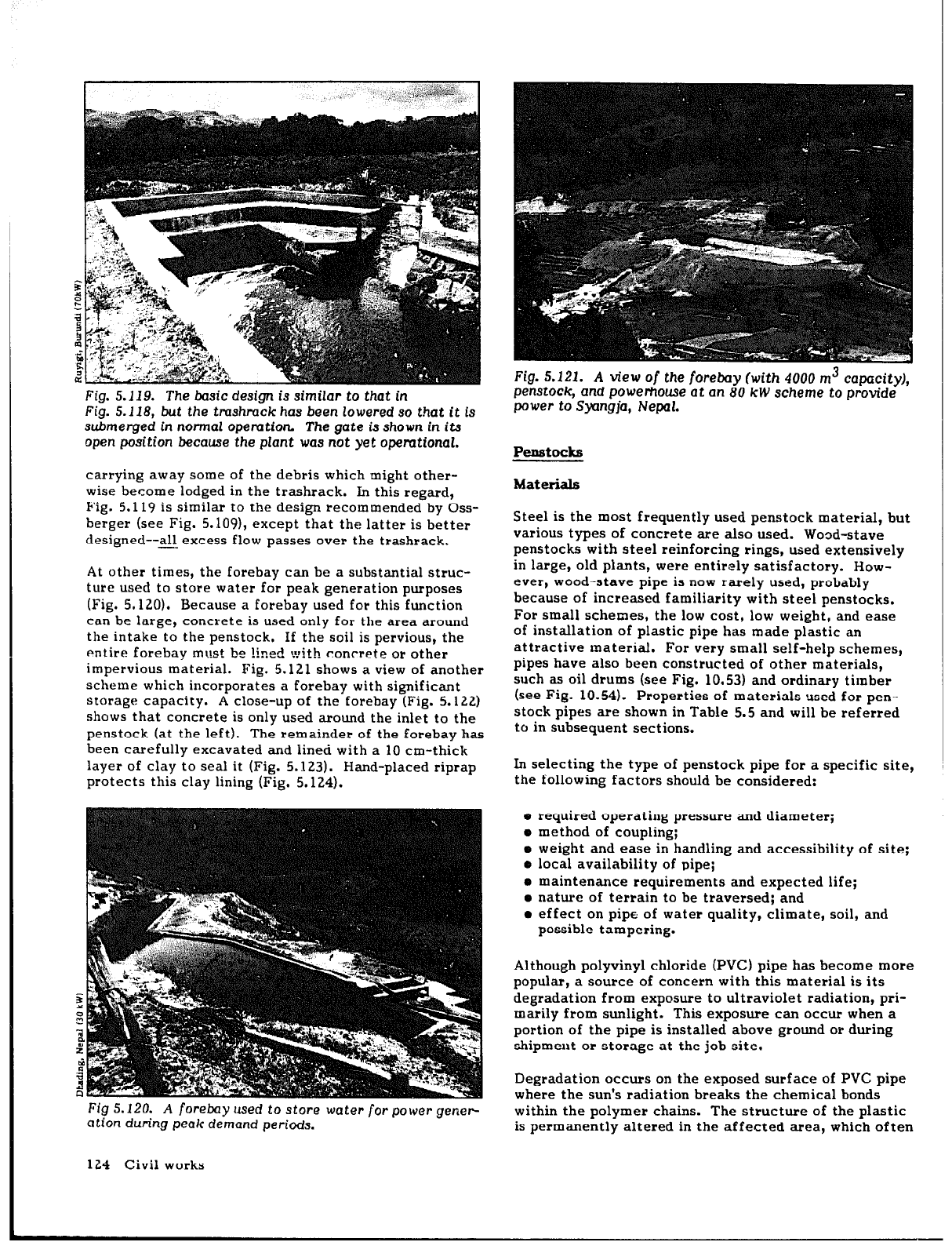
Fig. 5.119. The basic design is similar to
that in
Fig. 5.118,
but the
tmshmck has been lowered so that it is
submerged in normal opemtion The gate is shown
in
its
open position because the plant was
not
yet opemtional.
carrying away some of the debris which might other-
wise become lodged in the trashrack. In this regard,
Fig. 5.119 is similar to the design recommended by Oss-
berger (see Fig. 5.109), except that the latter is better
designed--all excess flow passes over the trashrack.
-
At other times, the forebay can be a substantial struc-
ture used to store water for peak generation purposes
(Fig. 5.120). Because a forebay used for this function
can be large, concrete is used only for the area around
the intake to the penstock. If the soil is pervious, the
entire forebay mlust b
e !ined with conrrete or other
impervious material. Fig. 5.121 shows a view of another
scheme which incorporates a forebay with significant
storage capacity. A close-up of the forebay (Fig. 5.122)
shows that concrete is only used around the inlet to the
penstock (at the left). The remainder of the forebay has
been carefully excavated and lined with a 10 cm-thick
layer of clay to seal it (Fig. 5.123). Hand-placed riprap
protects this clay lining (Fig. 5.124).
Fig 5.120.
A forebay used to
store water
for
power
gener-
a tion
during peak demand periods.
Fig. 5.121. A view
of
the forebay (with
4000
m3
capacity),
pet-stock, and powerhouse at
an
80 kW scheme to provide
power to Syangja, Nepal.
Penstocks
Materials
Steel is the most frequently used penstock material, but
various types of concrete are also used. Wood-stave
penstocks with steel reinforcing rings, used extensively
in large, old plants, were entirely satisfactory. How-
ever, wood-stave pipe is now rarely used, probably
because of increased familiarity with steel penstocks.
For small schemes, the low cost, low weight, and ease
of installation of plastic pipe has made plastic an
attractive material. For
very
small self-help schemes,
pipes have also been constructed of other materials,
such as oil drums (see Fig. 10.53) and ordinary timber
(see Fig. 10.54). Properties of materials used for pen-
stock pipes are shown in Table 5.5 and will be referred
to in subsequent sections.
In selecting the type of penstock pipe for a specific site,
the following factors should be considered:
e required operating pressure and diameter;
o method of coupling;
o weight and ease in handling and accessibility of site;
o local availability of pipe;
o maintenance requirements and expected life;
a nature of terrain to be traversed; and
l
effect on pipe of water quality, climate, soil, and
possible tampering.
Although polyvinyl chloride (PVC) pipe has become more
popular, a source of concern with this material is its
degradation from exposure to ultraviolet radiation, pri-
marily from sunlight. This exposure can occur when a
portion
of
the pipe is installed above ground or during
shipmeut or storage at the job site.
Degradation occurs on the exposed surface of PVC pipe
where the sun’s radiation breaks the chemical bonds
within the polymer chains. The structure of the plastic
is permanently altered in the affected area, which often
124 Civil works
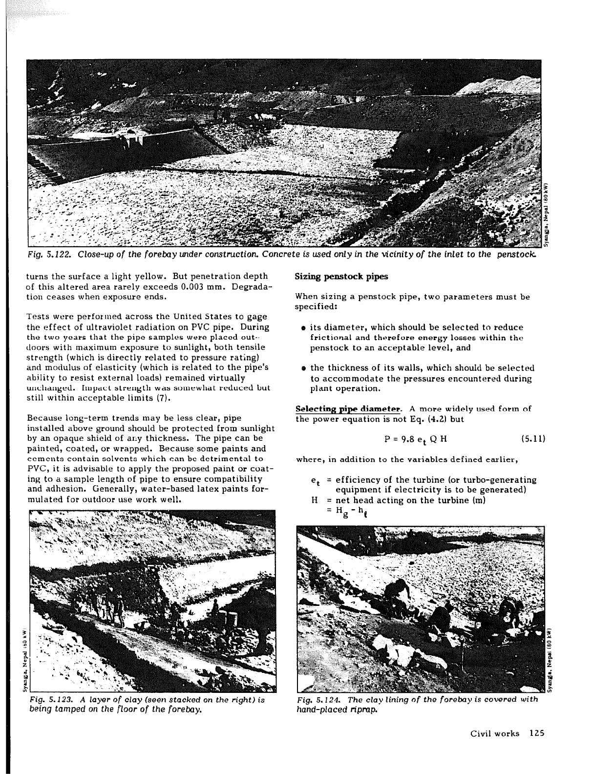
Fig. 5.122. Close-up of the forebay
under
construction Concrete is used only
in the
vicinity of the inlet to the penstock
turns the surface a light yellow. But penetration depth
of this altered area rarely exceeds 0.003 mm. Degrada-
tion ceases when exposure ends.
Tests were performed across the United States to gage
the effect of ultraviolet radiation on PVC pipe. During
the two years that the pipe samples were placed out.,
doors with maximum exposure to sunlight, both tensile
strength (which is directly related to pressure rating)
ant1 modulus of elasticity (which is related to the pipe’s
ability to resist external loads) remained virtually
unchanged. Impact strength was somewhat reduced but
still within acceptable limits (7).
Because long-term trends may be less clear, pipe
installed above ground should be protected from sunlight
by an opaque shield of ally thickness. The pipe can be
painted, coated, or wrapped. Because some paints and
cements contain solvents which can be detrimental to
PVC, it is advisable to apply the proposed paint or coat-
ing to a sample length of pipe to ensure compatibility
and adhesion. Generally, water-based latex paints for-
mulated for outdoor use work wel!.
Sizing
penstock
pipes
When sizing a penstock pipe, two parameters must be
specified:
o its diameter, which should be selected to reduce
frictional and therefore energy losses within the
penstock to an acceptable level, and
o the thickness of its walls, which shoulcl be selected
to accommodate the pressures encountered during
plant operation.
Selecting pipe diameter. A more widely used form of
the power equation is not Eq. (4.2) but
P = 9.8 et Q H
(5.11)
where, in addition to the variables defined earlier,
et
= efficiency of the turbine (or turbo-generating
equipment if electricity is to be generated)
H = net head acting on the turbine (m)
= Hg - h(
Fig. 5.123. A layer of clay (seen stacked
on the right) is
being tamped on the
floor
of
the foreboy.
Fig. 5.124.
The
clay lining of the forebay is covered with
hand-placed ripmp.
Civil works 125
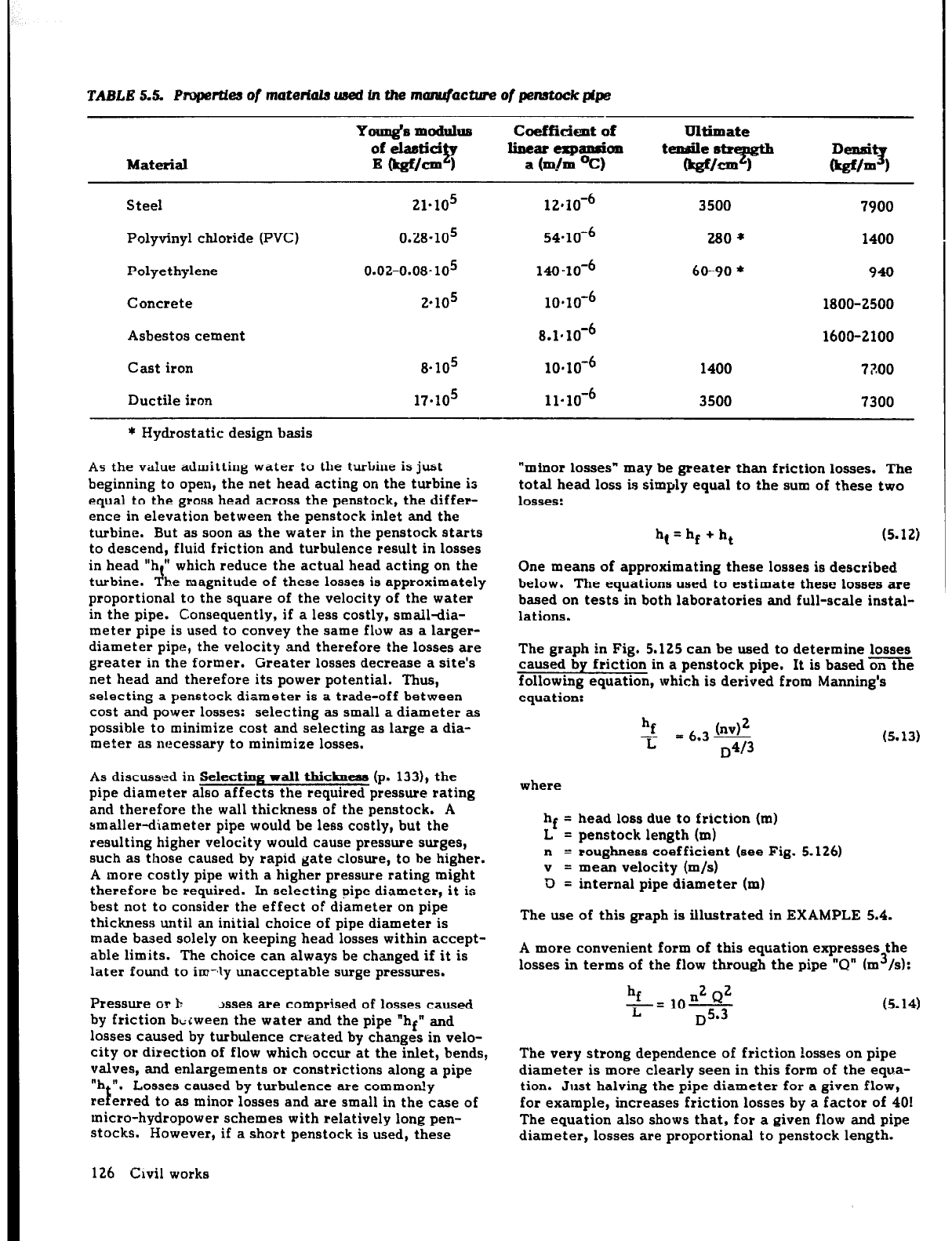
TABLE 5.5. Paopertfea of mateiiala used in the manufacture of penstock pipe
Youq&mcldlllus coefficient
of
of elastici linearcxpandcm
Material
P
Et&f/= 1
a (m./m Oc)
Steel 21.105 12*10-4
Polyvinyl chloride (PVC) 0.28.lo5 54.164
Polyethylene 0.02-0.08.105 140 “lo-6
Concrete 2.105 10.10-6
Asbestos cement 8.1*10+
Cast iron 8~10~ 10.10’6
Ductile iron 17.105 11-10-6
Ultimate
tende s
b&?fEtb
3500
280 *
60-90 *
1400
3500
Elzz 1
‘9
7900
1400
940
1800-2500
1600-2100
77.00
7300
* Hydrostatic design basis
As the value admitting water to the turbine is just
beginning to open, the net head acting on the turbine is
equal to the gross head across the penstock, the differ-
ence in elevation between the penstock inlet and the
turbine. But as soon as the water in the penstock starts
to descend, fluid friction and turbulence result in losses
in head “h ” which reduce the actual head acting on the
turbine. I!.. be magnitude of these losses is approximately
proportional to the square of the velocity of the water
in the pipe. Consequently, if a less costly, smail+a-
meter pipe is used to convey the same flow as a larger-
diameter pipe, the velocity and therefore the losses are
greater in the former. Greater losses decrease a site’s
net head and therefore its power potential. Thus,
selecting a penstock diameter is a trade-off between
cost and power losses: selecting as small a diameter as
possible to minimize cost and selecting as large a dia-
meter as necessary to minimize losses.
As discussed in Selecting wall thickness (p* 1331, the
pipe diameter also affects the required pressure rating
and therefore the wall thickness of the penstock. A
smaller-diameter pipe would be less costly, but the
resulting higher velocity would cause pressure surges,
such as those caused by rapid gate closure, to be higher.
A more costly pipe with a higher pressure rating might
therefore be required. In selecting pipe diameter, it is
best not to consider the effect of diameter on pipe
thickness until an initial choice of pipe diameter is
made based solely on keeping head losses within accept-
able limits. The choice can always be changed if it is
later found to im-ly unacceptable surge pressures.
Pressure or b
>sses are comprised of losses caused
by friction bcrween the water and the pipe “hf” and
losses caused by turbulence created by changes in velo-
city or direction of flow which occur at the inlet, bends,
valves, and enlargements or constrictions along a pipe
“h n,
re
E
Losses caused by turbulence are commody
erred to as minor losses and are small in the case of
micro-hydropower schemes with relatively long pen-
stocks. However, if a short penstock is used, these
126 Civil works
“minor
losses” may be greater than friction losses. The
total head loss is simply equal to the sum of these two
losses:
hl = hf + ht (5.12)
One means of approximating these losses is described
below. The equations used to estimate these losses are
based on tests in both laboratories and full-scale instal-
lations.
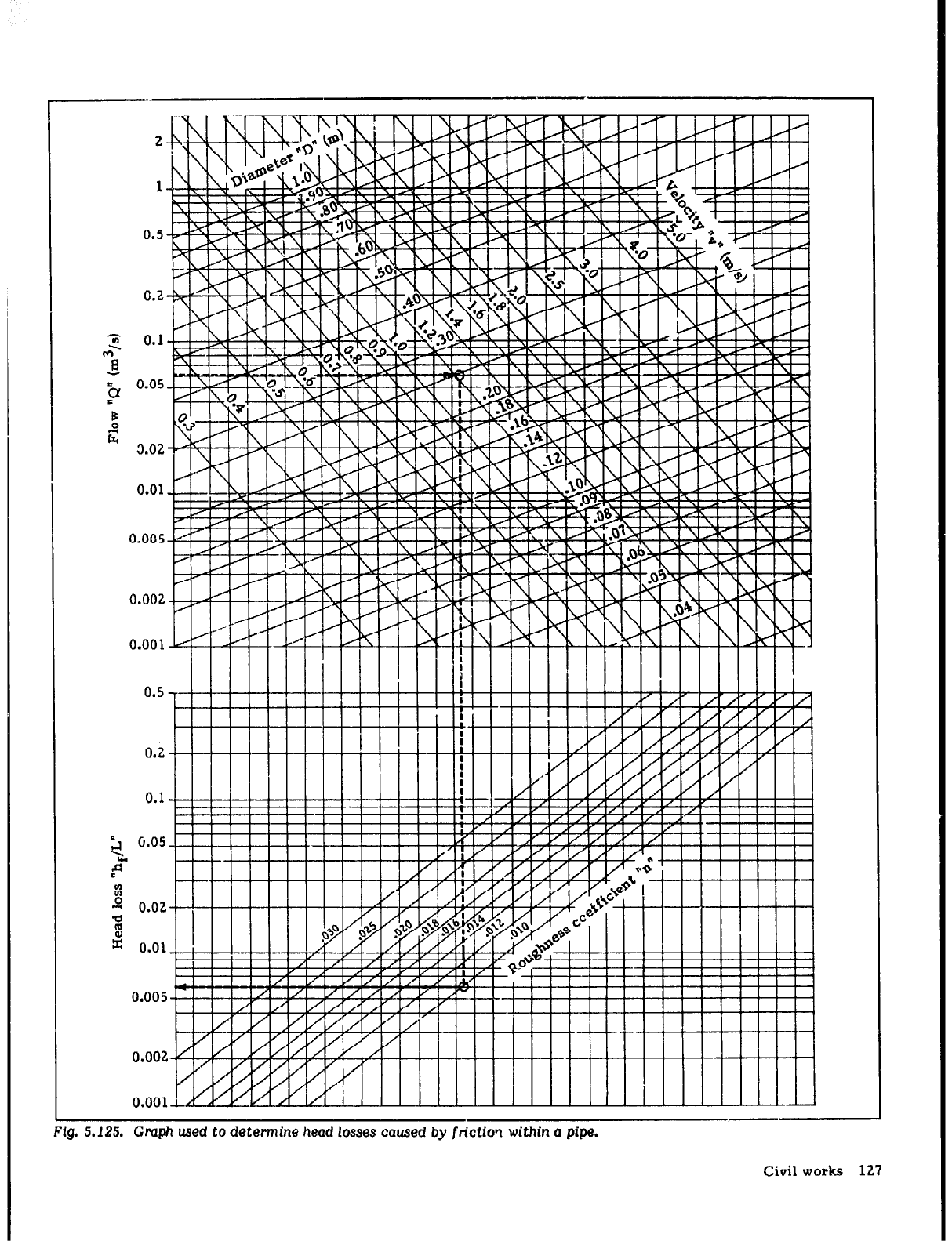
The graph in Fig. 5.125 can be used to determine losses
caused by friction in a penstock pipe. It is based on the
following equation, which is derived from Manning’s
equation:
hf
?I
= 6.3s3 (5.13)
where
= head loss due to friction (m)
= penstock length (ml
n = roughness coefficient (see Fig. 5.126)
v = mean velocity (m/s)
D = internal pipe diameter (m)
The use of this graph is illustrated in EXAMPLE 5.4.
A more convenient form of this equation
expresses
the
losses in terms of the flow through the pipe “Q” (m3/s):
hf n2 Q2
r= lo-
D5.3
(5.14)
The very strong dependence of friction losses on pipe
diameter is more clearly seen in this form of the equa-
tion. Just halving the pipe diameter for a given flow,
for example, increases friction losses by a factor of 401
The equation also shows that, for a given flow and pipe
diameter, losses are proportional to penstock length.
1
0.5
0.2
0.1
2
0.05
u
I
\LLY?j
llllllillllllllll!llllll!
* i i i
i i i .kl Xi ” !+‘!-‘! *’ *! ’ /
0.002
0.0011 rmml
11
11 11 11
i
Fig. 5.125. Graph used
to determine head losses
caused by
frictfo? within a
pipe.
Civil works 127
Plastic
Welded steel
Wood stave
Concrete
very smooth
made from steel forms
with rough farms
Galvanized iron
Corrugated metal
n (roughness coefficient)
i
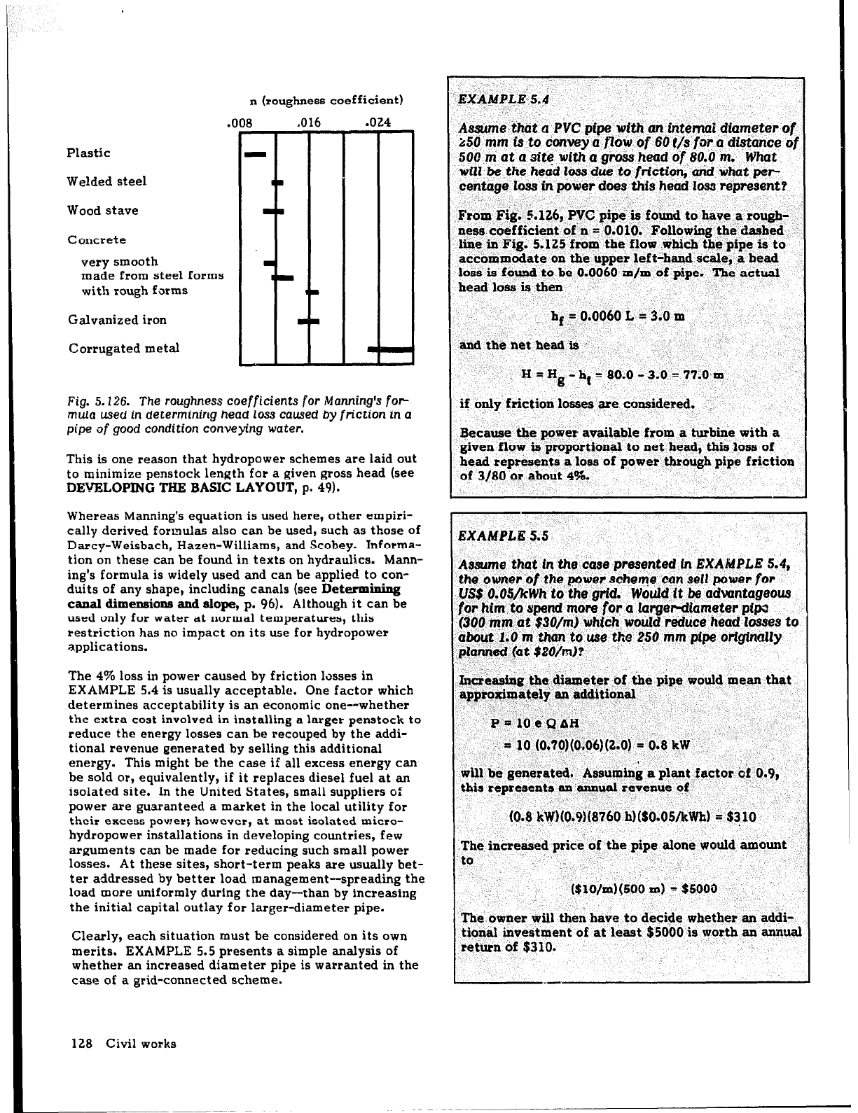
Fig. 5.126. The roughness coefficients
for
Manning’s for-
mula used in
determining head loss
caused by
friction
in a
pipe
of
good
condition
conveying
water.
This is one reason that hydropower schemes are laid out
to minimize penstock length for a given gross head (see
DEVELOPING THE BASIC LAYOUT,
p. 49).
Whereas Manning’s equation is used here, other empiri-
cally derived formulas also can be used, such as those of
Darcy-Weisbach, Hazen-Williams, and Scobey. Informa-
tion on these can be found in texts on hydraulics. Mann-
ing’s formula is widely used and can be applied to con-
duits of any shape, including canals (see
Determining
canal
dimensions
and slope, p.
96).
Although it can be
used only for water at normal temperatures, this
restriction has no impact on its use for hydropower
applications.
The 4% loss in power caused by friction ltisses in
EXAMPLE 5.4 is usually acceptable. One factor which
determines acceptability is an economic one--whether
the extra cost involved in installing a larger penstock to
reduce the energy losses can be recouped by the addi-
tional revenue generated by selling this additional
energy. This might be the case if all excess energy can
be sold or, equivalently, if it replaces diesel fuel at an
isolated site. In the United States, small suppliers of
power are guaranteed a market in the local utility for
their excess power; however, at mast isalated micro-
hydropower installations in developing countries, few
arguments can be made for reducing such small power
losses. At these sites, short-term peaks are usually bet-
ter addressed by better load management-spreading the
load more uniformly
during
the day-than by increasing
the initial capital outlay for larger-diameter pipe.
Clearly, each situation must be considered on its own
merits. EXAMPLE 5.5 presents a simple analysis of
whether an increased diameter pipe is warranted in the
case of a grid-connected scheme.
-_
A&e ‘that d PVC pipe’ with an intemaE diameter of
2~50
mm is to convey a flbw
of
'60
P/s for u dfstance of
500 m at a site with a ghxk
head cif,8O.b m.
What
will .@e:the head loss due
to
friction,
arid what pep
centage loss in power does
this
head IO= represent?
From
Fig.
5.126, V-C pip& ,+ found to have ,a rough- ‘.
ness.coefficient’ of II =‘O.OlO: %ollowing the’elaqhed
l&e in Fig. 5.125 from the floF ,which the pipe is Qo
accomu+ate on the upper leftaand scale, a head
losi3
is found to be 0.0060 m/m of -pipe. The actual
head loss is then
I
hf 5 0.006OL =3.0m
and the net head is
H=Hg-ll*=80.0-3.0=77;0~m.
if bnli friction losses are consjdered.
::
Because the poyer‘available from a turbine with a
given flow is proportional to net head, this loss of
head represents a loss of power through pipe friction
of 3/80 or about 4%.
EXAMPLE 5.5
Assume that
in the case presented In EXAMPLE 5.4,
the owner
of
the power schem-e can sell power
for
US$ O.OS/kWh to the
grid.
Would it be adwntageous
for
him’.!0 spend more
for a larger-diameter
pipa
(300 mm~bt $30/m) which. would
reduce
head losses to
aiitji4t I:0 in than to use the 250 mm pipe
originally
pbnrk?d(~t$20/m)?
-
,J&reasiag the diameter ,of the pipe would mean that
approximately an additional
., I” -.
._
P=.-lOeQbH, I
= 10,(0.7~)(0..~6~(2.0) =: 0.8 kW
will be generate& +ssu+i& a plant factor $ 0.9,
this represents an annual revenue qf
< ,. ,’
(0.8 -k~,@.&8ikO h)($O.OS/kWh) A’$? 10
.The, increa&d price of the pipe alone would amount
tp. ^’ “-._
: ‘,
. .
The owner will then have to decide whether an addi-
tional investment of at least $5000 is worth an annual
return of
$310.
..-
128 Civil works
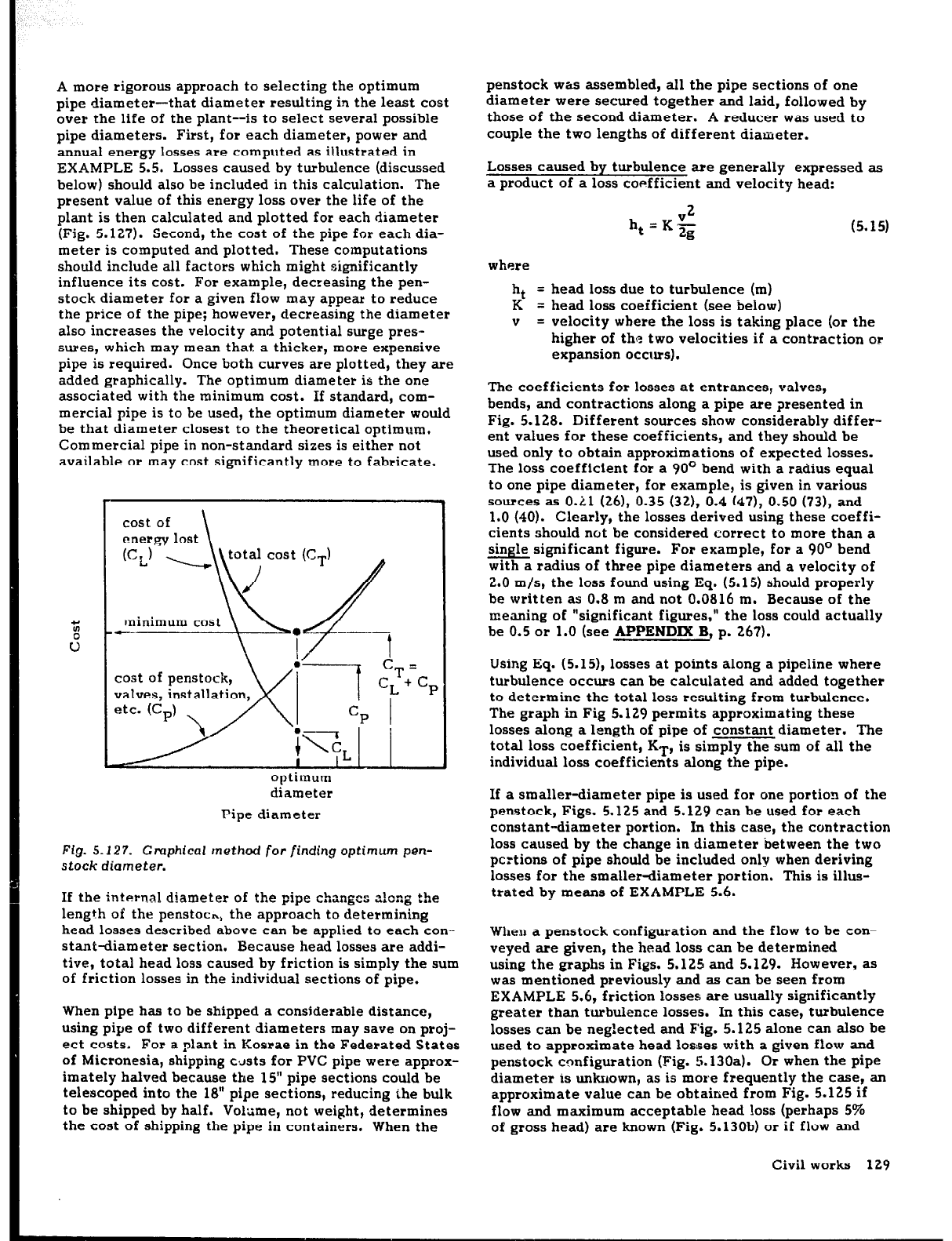
A more rigorous approach to selecting the optimum
pipe diameter-that diameter resulting in the least cost
over the life of the plant--is to select several possible
pipe diameters. First, for each diameter, power and
annual energy losses are computed as illustrated in
EXAMPLE 5.5. Losses caused by turbulence (discussed
below) should also be included in this calculation. The
present value of this energy loss over the life of the
plant is then calculated and plotted for each diameter
(Fig. 5.127). Second, the cost of the pipe for each dia-
meter is computed and plotted. These computations
should include all factors which might significantly
influence its cost. For example, decreasing the pen-
stock diameter for a given flow may appear to reduce
the price of the pipe; however, decreasing the diameter
also increases the velocity and potential surge pres-
sures, which may mean that a thicker, more expensive
pipe is required. Once both curves are plotted, they are
added graphically. The optimum diameter is the one
associated with the minimum cost. If standard, com-
mercial pipe is to be used, the optimum diameter would
be that diameter closest to the theoretical optimum,
Commercial pipe in non-standard sizes is either not
available or may cost significantly more to fabricate.
minimum cost
t--
cost of penstock,
valves, installation,
optimum
diameter
Pipe diameter
Fig. 5.127.
Graphical
rnethod for finding optimum
pen-
stock diameter.
If the internal diameter of the pipe changes a!ong the
length of the penstoch, the approach to determining
head losses described above can be applied to each con-
stant-diameter section. Because head losses are addi-
tive, total head loss caused by friction is simply the sum
of friction losses in the individual sections of pipe.
When pipe has to be shipped a considerable distance,
using pipe of two different diameters may save on proj-
ect costs. For a plant in Kosrae in the Federated States
of Micronesia, shipping c.Jsts for PVC pipe were approx-
imately halved because
tbe
15” pipe sections could be
telescoped into the 18” pipe sections, reducing the bulk
to be shipped by half. Volume, not weight, determines
the cost
of
shipping the pipe in containers. When the
penstock was assembled, all the pipe sections of one
diameter were secured together and laid, followed by
those of the second diameter. A reducer was used to
couple the two lengths of different diameter.
Losses caused by turbulence are generally expressed as
a product of a loss coefficient and velocity head:
V2
ht=Kg
(5.15)
where
ht
= head loss due to turbulence (m)
K
= head loss coefficient (see below)
V
= velocity where the loss is taking place (or the
higher of the two velocities if a contraction or
expansion occurs).
The coefficients for losses at entrances, valves,
bends, and contractions along a pipe are presented in
Fig. 5.128. Different sources show considerably differ-
ent values
for
these coefficients, and they should be
used only to obtain approximations of expected losses.
The loss coefficient for a 90° bend with a radius equal
to one pipe diameter, for example, is given in various
sources as O.Ll
(261, 0.35 (321, 0.4 (471, 0.50 (731,
and
1.0 (40). Clearly, the losses derived using these coeffi-
cients should not be considered correct to more than a
single significant figure. For example, for a 90’ bend
with a radius of three pipe diameters and a velocity of
2.0 m/s, the loss found using Eq. (5.15) should properly
be written as 0.8 m and not 0.0816 m. Because of the
meaning
of
“significant figures,” the loss could actually
be
0.5
& 1.0 (see APPENDIX B; p. 267).
Using Eq. (5.15), losses at points along a pipeline where
turbulence occurs can be calculated and added together
to determine the total loss resulting from turbulence.
The graph in Fig 5.129 permits approximating these
losses along a length of pipe of constant diameter. The
total
loss
coefficient, KT,
is simply the sum of all the
individual loss coefficients along the pipe.
If a smaller-diameter pipe is used for one portion of the
penstock, Figs. 5.125 and 5,129 can be used for each
constant-diameter portion. In this case, the contraction
loss caused by the change in diameter between the two
pcrtions of pipe should be included only when deriving
losses for the smaller-diameter portion. This is illus-
trated by means of EXAMPLE 5.6.
When a penstock configuration and the flow to be con-
veyed are given, the head loss can be determined
using the graphs in Figs. 5.125 and 5.129. However, as
was mentioned previously and as can
be
seen from
EXAMPLE 5.6, friction losses are usually significantly
greater than turbulence losses. In this case, turbulence
losses can be neg!ected and Fig. 5.125 alone can also be
used to approximate head losses with a given flow and
penstock configuration (Fig. 5.130a).
Or
when the pipe
diameter is unknown, as is more frequently the case, an
approximate value can be obtained from Fig. 5.125 if
flow and maximum acceptable head loss (perhaps 5%
of gross head) are known (Fig. 5.130b) or if flow and
Civil works 129