Inversin R. Allen Micro-hydropower Sourcebook
Подождите немного. Документ загружается.

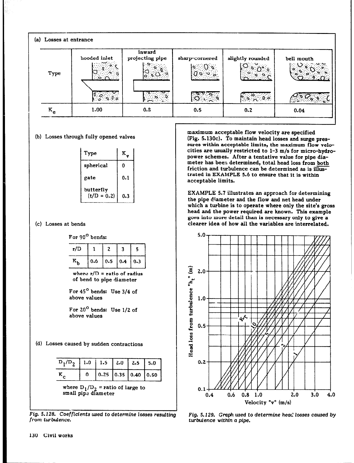
(a) Losses at entrance
I
I
inward
hooded inlet projecting pipe
Type
Ke
I
1.00
!
0.8
(b) Losses through fully opened valves
Tn=
KV
-
spherical
0
t
gate
0.1
butterfly
(t/D = 0.2) 0.3
(c) Losses at bends
For 90’ bends:
where r/D = ratio of radius
of bend to pipe diameter
For 45’ bends: Use 314 of
above values
‘For 20’ bends: Use l/2 of
above values
(d) Losses caused by sudden contractions
where D1/D2 = ratio of large to
small pip2 drameter
sharp-cornered
I
slightly rounded
bell mouth
0.04
maximum acceptable flow velocity are specified
(Fig. 5.130~). To maintain head losses and surge pres-
sures within acceptable limits, the maximum flow velo-
cities are usually restricted to l-3 m/s for micro-hydro-
power schemes. After a tentative value for pipe dia-
meter has been determined, total head loss from both
friction and turbulence can be determined as is ils
trated in EXAMPLE 5.6 to ensure that it is within
acceptable limits.
EXAMPLE 5.7 illustrates an approach for determining
the pipe diameter and the flow and net head under
which a turbine is to operate where only the site’s gross
head and the power required are known. This example
goes into more detail than is necessary only to give a
clearer idea of how all the variables are interrelated.
5.0
/5
1
016 018 110 2.0 ?
Velocity “v” (m/s)
5.128. Coefficfents used to determine losses resulting
rom turbulence.
Fig. 5.129. Graph used to determine head losses caused by
turbulence within
a pipe.
130 Civil works
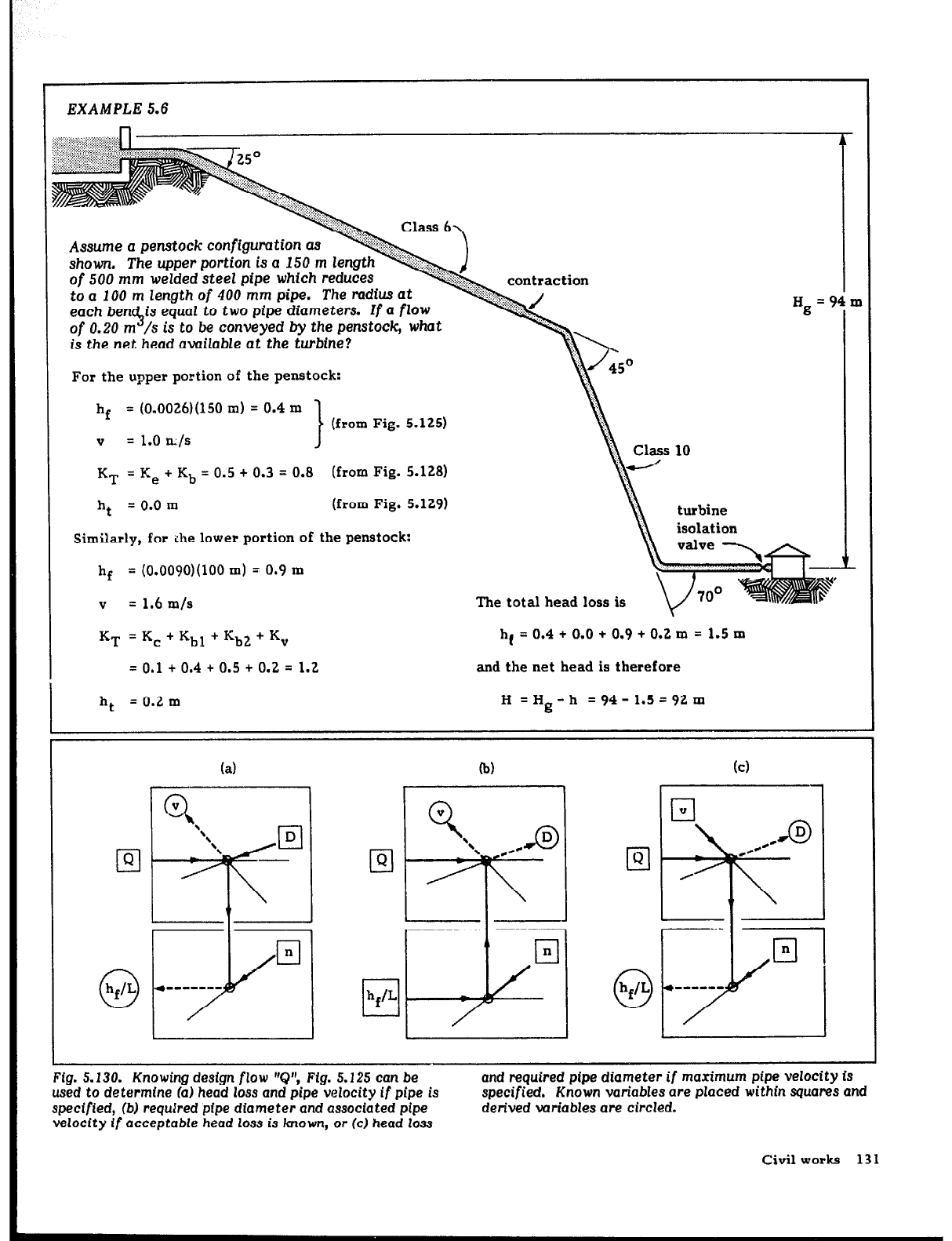
EXAMPLES.6
of 500
mm
welded steel
pfpe which
reduces
to
a
100 m length
of
400 mm pipe.
The radius at
each benc$is equal to two pipe diameters.
Zf
a flow
of 0.20
m
/s
is
to be
conveyed
by
the
penstock, what
is the net head available at the turbine?
For the upper portion of the penstock:
= (0.0026)(150 m) = 0.4 m
V
= 1.0 m/s
KT = K, + Kb = 0.5 + 0.3 = 0.8 (from Fig. 5.128)
ht
= 0.0 m
(from Fig. 5.129)
Similarly, for ;he lower portion of the penstock:
h f
= (0.0090)(100 m) = 0.9 m
V
= 1.6 m/s
The total head loss is
KT = Kc + Khl t Kh2 t K,
hf = 0.4 + 0.0 + 0.9 t 0.2 m = 1.5 m
= 0.1 t 0.4 t 0.5 t 0.2 = 1.2
and the net head is therefore
ht
= 0.2 m H =Hg -h = 94 - 1.5 = 92 m
(a)
b)
ICI
Fig. 5.130. Knowing
design flow ‘Q”, Fig. 5.125
can
be
used to determine fa) head loss
and
pipe velocity
if
pipe is
specified, (bj required
pipe
diameter and associated pipe
velocity
if
acceptable head loss is known, or (c) head loss
and required ptpe diameter if maximum pipe velocity is
specified.
Known
variables are placed within squares
and
derived wriables are circled.
Civil
works
131
1
EXAMPLE 5.7
An 85
m-long steel penstock is to have
a
sharp-cor-
nered inlet at the forebay, two 45’ bends of moder-
ate radius, and
a gate
valve located
in the power-
house. The
turbine,
which operates under a gross
nead of 35.0
m, has an
efficiency of 70%, and is to
genemte 18 kW. Assume that standard pipe is awil-
able in
diameters
which are
multiples
of
50
mm.
(a)
What diameter pipe wouEd
be required if head loss
is to remain within 5%
of gross
head?
(b) With the pipe diameter which
has been
selected,
what would be the net head
under
which the tur-
bine
will
operate
if
both friction
and turbulence
losses are considered?
Cc) If 250 mm steel pipe is
difficult
to procure, can a
200 mm PVC pipe be used?
(a) A number of approaches can be used to solve this
problem. Initially assume that turbulence losses are
negligible and that only friction losses “hf” are to be
considered. As shown in Fig. 5.130b, Fig. 5.125 can
then be used to estimate the required penstock pipe
diameter if flow is known.
The flow required by the turbine to generate 18 kW
depends on the net head under which it operates and
can be determined by the power equation (Eq. (5.11)].
For an initial estimate, assume that the net head will
be the gross head less 5% or about 33 m. F:om the
power equation, the required flow then would be
P
Q = 9,8 et Hg = 0.080 m3/s
Restricting the head loss to 5% implies that
h f hf 2
-=-
L H
Iii L
= (0.05)(g) = 0.021
From Fig. 5.126, the roughness of a welded steel pipe
is about C.012. From Fi
q 5.125, a steel pipe to con-
vey the required 0.080 m /s at the site with a head
loss “h /L” of 0.021 would
reyGre
a diameter of
about 4 -30 mm. To keep losses within 5%, a standard
250 ma: steel pipe would be required.
(b) If a flow of 0.080 m3/s descends a 250 mm-dia-
meter penstock, the loss in head caused by friction
can be calculated to be about 1.2 m using Eq. (5.14)
or the graph in Fig. 5.125. Continuing to assume that
turbulence losses are negligible, the net head actually
will then be 33.8 m. Because the net head is greater
than initially assumed, the turbine will require
slightly less flow to generate the required power.
Using the power equation as was done in (a), the
required flow under this revised head is found to be
0.078 m3/s. With this more precise value for flow,
the penstock friction losses are still found to be
about 1.2 m. When analyzing any site, this process of
iteration can be continued in order to approach the
exact value of head loss, but one or two iterations
generally suffice to obtain the necessary accuracy.
Now that the penstock friction losses have been
determined, the actual losses caused by turbulence
can be determined from Eq. (5.15) or Fig. 5.129 if
penstock velocity is known. With a flow of
0.078 m3/s decending a 250 mm-diameter penstock,
the velocity can be determined to be
Q Q
v =-
A
= - = 1.6 m/s
z D2/4
The coefficient of losses from turbulence is the sum
of the coefficient of losses of each point where losses
are incurred-the inlet, bends, and gate valve.
Therefore, from Fig. 5.128,
KT = 0.5 t 2 (0.3) + 0.1 = 1.2
and the losses can be derived from Eq. (5.15)
or
Fig. 5.129 to be about 0.2 m. The actual head is
therefore closer to 33.6 m if losses from both friction
and turbulence are included.
Because the net head has
now
been determined to be
slightly less than the 33.8 m calculated considering
only fri tion losses, a flow slightly greater than
5
0.078 m /s would now be required to generate 18 kW.
The steps performed above can be repeated assuming
a net head of 33.6 m rather than 33.8 m to obtain a
more precise value for the losses caused by friction
and turbulence. However, changes in the values of
flow and net head will be negligible.
(c) To determine whether a 200 mm-diameter PVC
pipe can be used, the above procedure is repeated. In
this case, the net head is found to be 32.2 m.
Whereas a penstock of reduced diameter can be used,
the reduced operating head means that the flow
required to generate 18 kW has increased very
slightly, requiring a slightly larger turbine to gener-
ate the same power. Although penstock velocity is
now larger, the surge pressures are not necessarily
higher because of the lower elasticity of PVC. (This
will be discussed in Selecting rail thicknw, p. 133.)
If a mathematical rather than graphical sol*ltion is
Although it is straightforward to determine either “h( It
desired, it is possible to incor. -dte both friction and
or “Q” if the other is known and the pipe diameter is
turbulence losses in a single equation for the case of a
given, this equation cannot be solved in closed form for
penstock with a constant diameter:
pipe diameter. If friction is indeed the major source
of
the losses, the second term can be neglected and the
ht = ht + hf = Q
(5.16)
resulting equation can then be solved for pipe diameter
for a given head loss and flow:
132 Civil works
D= 10(Qn)2 O-l9
[ 1
(hO IL)
(5.17)
Commercial pipe of standard diameters is often used for
micro-hydropower schemes. Because available pipe
diameters probably bracket the desired diameter
derived above, selecting the larger of the two diameters
will keep.losses and velocities within desirable limits.
Once pipe diameter has been established, actual head
losses in the pipe, including those caused by turbulence,
can be determined with the original, longer equation,
Eq. (5.16), to ensure that total head loss is acceptable.
Equivalently, the graphs may be used.
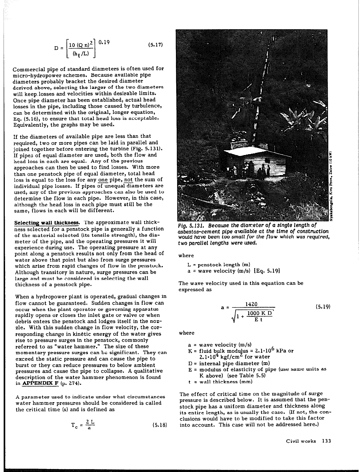
If the diameters of available pipe are less than that
required, two or more pipes can be laid in parallel and
joined together before entering the turbine (Fig. 5.131).
If pipes of equal diameter are used, both the flow and
head loss in each are equal. Any of the previous
approaches can then be used to find losses. With more
than one penstock pipe of equal diameter, total head
loss is equal to the loss for any one pipe, not the sum of
individual pipe losses. If pipes of unequal diameters are
used, any of the previous approaches can also be used to
determine the flow in each pipe. However, in this case,
although the head loss in each pipe must still be the
same, flows in each will be different.
Selecting wall thickness. The approximate wall thick-
ness selected for a penstock pipe is generally a function
of the material selected (its tensile strength), the dia-
meter of the pipe, and the operating pressures it will
experience during use. The operating pressure at any
point along a penstock results not only from the head of
water above that point but also from surge pressures
which arise from rapid changes of flow in the penstock.
Although transitory in nature, surge pressures can be
large and must be considered in selecting the wall
thickness of a penstock pipe.
When a hydropower plant is operated, gradual changes in
flow cannot be guaranteed. Sudden changes in flow can
occur when the plant operator or governing apparatus
rapidly opens or closes the inlet gate or valve or when
debris enters the penstock and lodges itself in the noz-
zle. With this sudden change in flow velocity, the cor-
responding change in kinetic energy of the water gives
rise to pressure surges in the penstock, commonly
referred to as “water hammer.” The size of these
momentary pressure surges can be significant. They can
exceed the static pressure and can cause the pipe to
burst or they can reduce pressures to below ambient
pressures and cause the pipe to collapse. A qualitative
description of the water hammer phenomenon is found
in APPENDIX F (p. 274).
A parameter used to indicate under what circumstances
water hammer pressures should be considered is called
the critical time (s) and is defined as
(5.18)
1420
a= (5.19)
$-Fy-
Fig. 5.131. Because the diameter of a single length of
asbestos-cement pipe available at the tfme of constructIon
would have been too small for the flow which was required,
two pamllel lengths were used.
where
L = penstock length (m)
a = wave velocity (m/s) [Eq. 5.19)
The wave velocity used in this equation can be
expressed as
where
a = wave velocity (m/s)
K = fluid bulk modulus = 2.1*106 kPa or
2.1.104 kgf/cm’ for water
D = internal pipe diameter (m)
E = modulus of elasticity of pipe (use same units as
K above) (see Table 5.5)
t = wall thickness (mm)
The effect of critical time on the magnitude of surge
pressure is described below. It is assumed that the pen-
stock pipe has a uniform diameter and thickness along
its entire length, as is usually the case. (If not, the con-
clusions would have to be modified to take this factor
into account. This case will not be addressed here.)
Civil works 133
The magnitude of the surge pressures which will be
encountered in the operation of a plant depends on how
quickly flow velocity changes in the penstock. If this
change occurs in less than critical time, maximum surge
pressures will be experienced. If the valve is closed
instantaneously, the entire length of penstock will
experience this pressure peak. As more time is taken to
close the valve, a decreasing length of pipe from the
valve up is subjected to this peak. When the time of
closure equals the critical time, the peak pressure is
felt only by the valve at the end of the penstock. Jou-
kovsky’s equation expresses the value of this peak pres-
sure as:
aAv
ps= g
where
ps
= maximum surge pressure (in m of water)
a
= wave velocity (m/s), see Eq. (5.19)
Av = change in flow velocity in pipe (m/s)
g
= acceleration due to gravity = 9.81 m/s2
EXAMPLE 5.8 illustrates how peak surge pressures at a
specific site can be determined.
If uniform valve closure is relatively slow, maximum
pressures will be experienced at the valve, with the
pressure rise decreasing to zero uniformly along the
length of the penstock. If hydraulic losses in the pen-
stock are assumed to be insignificant, an approximate
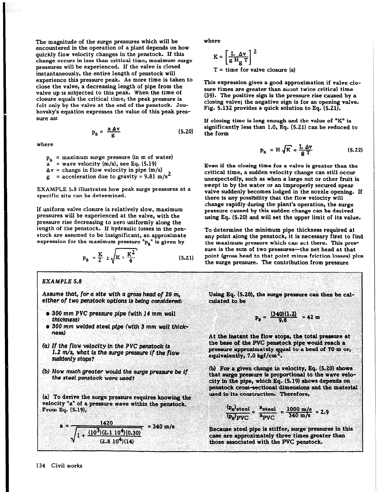
expression for the maximum pressure “ps” is given by
r
\
P, =$ *&+$
where
LAv ’
IL= gHgT
[ I
T = time for valve closure (s)
This expression gives a good approximation if valve clo-
sure times are greater than about twice critical time
(39). The positive sign is the pressure rise caused by a
closing valve; the negative sign is for an opening valve.
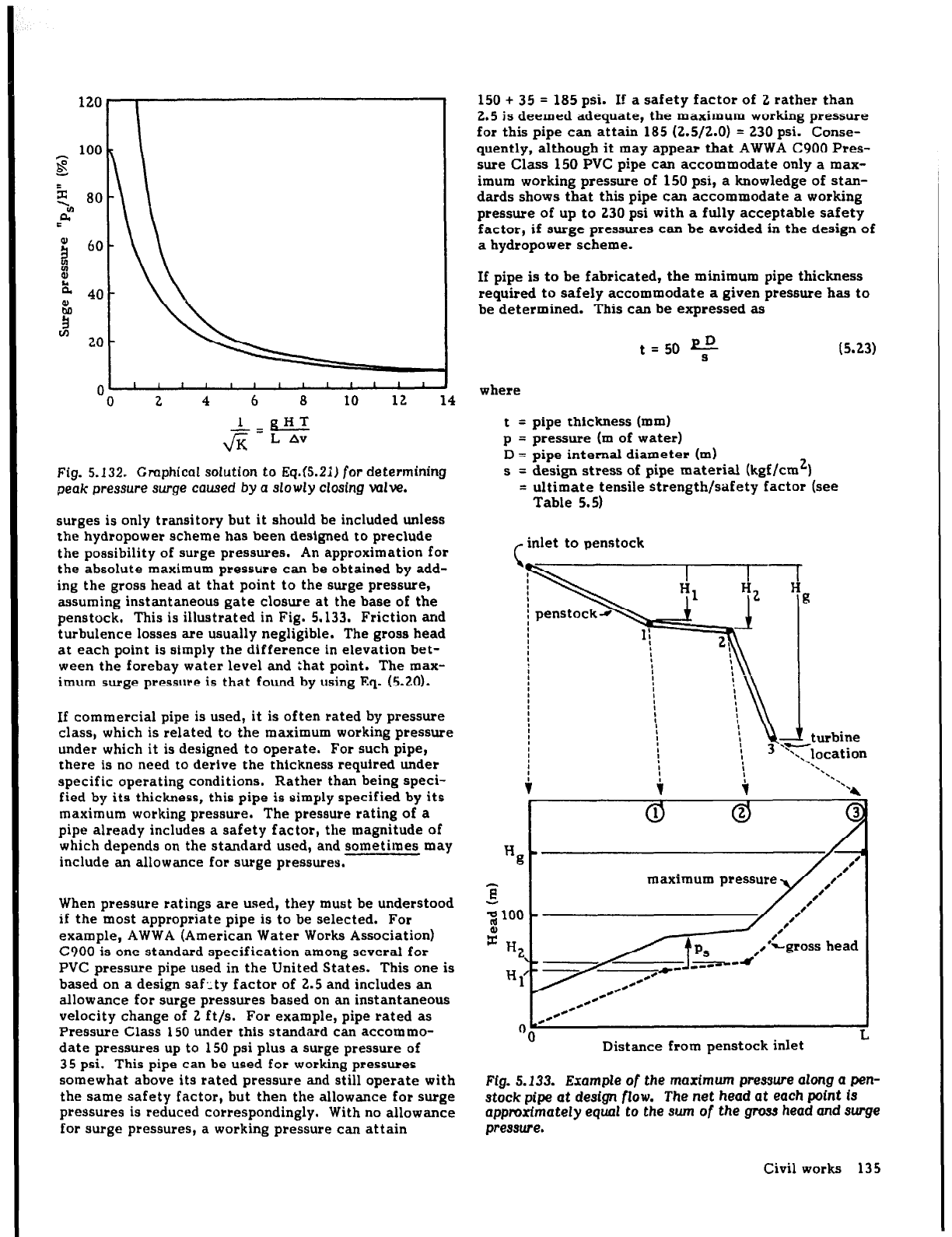
Fig. 5.132 provides a quick solution to Eq. (5.21).
If closing time is long enough and the value of “K” is
significantly less than 1.0, Eq. (5.21) can be reduced to
the form
ps = He=*
(5.22)
Even if the closing time for a valve is greater than the
critical time, a sudden velocity change can still occur
unexpectedly, such as when a large nut or other fruit is
swept in by the water or an improperly secured spear
valve suddenly becomes iodged in the nozzle opening. If
there is any possibility that the flow velocity will
change rapidly during the plant’s operation, the surge
pressure
caused
by this sudden change can be derived
using Eq. (5.20) and will set the upper limit of its value.
To determine the minimum pipe thickness required at
any point along the penstock, it is necessary first to find
the maximum pressure which can act there. This pres-
sure is the sum of two pressures-the net head at that
point (gross head to that point minus friction losses) plus
the surge pressure. The contribution from pressure
134 Civil works
J
-0 2 4 6
a
10 12 14
Fig. 5.132. Gmphical solution to Eq.(5.21) for determining
peak pressure surge caused by a slowly Closing valve.
surges is only transitory but it should be included unless
the hydropower scheme has been designed to preclude
the possibility
of
surge pressures. An approximation for
the absolute maximum pressure can be obtained by add-
ing the gross head at that point to the surge pressure,
assuming instantaneous gate closure at the base of the
penstock. This is illustrated in Fig. 5.133. Friction and
turbulence losses are usually negligible. The
gross
head
at each point is simply the difference in elevation bet-
ween the forebay water level and that point. The max-
imum surge pressure is that found by using Eq. (5.20).
If commercial pipe is used, it is often rated by pressure
class, which is related to the maximum working pressure
under which it is designed to operate. For such pipe,
there is no need to derive the thickness required under
specific operating conditions. Rather than being speci-
fied by its thickness, this pipe is simply specified by its
maximum working pressure. The pressure rating of a
pipe already includes a safety factor, the magnitude of
which depends on the standard used, and sometimes may
include an allowance for surge pressures.
When pressure ratings are used, they must be understood
if the most appropriate pipe is to be selected. For
example, AWWA (American Water Works Association)
C900 is one standard specification among several for
PVC pressure pipe used in the United States. This one is
based on a design saf 2 ty factor of 2.5 and includes an
allowance for surge pressures based on an instantaneous
velocity change of 2 ft/s. For example, pipe rated as
Pressure Class 150 under this standard can accommo-
date pressures up to 150 psi plus a surge pressure of
35 psi. This pipe can be used for working pressures
somewhat above its rated pressure and still operate with
the same safety factor, but then the allowance for surge
pressures is reduced correspondingly. With no allowance
for surge pressures, a working pressure can attain
150 + 35 = 185 psi. If a safety factor of 2 rather than
2.5 is deemed adequate, the maximum working pressure
for this pipe can attain 185 (2.5/2.0) = 230 psi. Conse-
quently, although it may appear that AWWA C900 Pres-
sure Class 150 PVC pipe can accommodate only a max-
imum working pressure of 150 psi, a knowledge of stan-
dards shows that this pipe can accommodate a working
pressure of up to 230 psi with a fully acceptable safety
factor, if surge pressures can be avoided in the design of
a hydropower scheme.
If pipe is to be fabricated, the minimum pipe thickness
required to safely accommodate a given pressure has to
be determined. This can be expressed as
t=50 fi
S
where
t = pipe thickness (mm)
p = pressure (m of water)
D = pipe internal diameter (m)
s = design stress of pipe material (kgf/cm2)
=
ultimate tensile strength/safety factor (see
Table 5.5)
,- inlet to penstock
Hg
t / 0
3
maximum pressure
2100 h
al
x HZ,
I
/f
ps
*-
c*
c*- ---
*-
c-
#-
,H
*c
*-
OO
Distance from penstock inlet
Fig. 5.133. Example
of
the
maximum
pressure along a pen-
stock
pipe
at design
flow.
The
net head at each point is
approximately
equal
to the
sum
of the
gross head and surge
pressure.
Civil works 135
Because the maximum pressure changes with the dis-
tance along the penstock, the minimum required thick-
ness would change accordingly. However, commercial
pipe is available in standard wall thicknesses. Even if
steel pipe is fabricated, steel sheet is also available in
standard thicknesses. It is therefore necessary to find
the pipe or pipe material with the standard thickness
closest to that derived using the previous equation. If
pipe with a common single thickness is used for the
entire penstock, the maximum pressure at the lower end
of the turbine would set the thickness of the pipe.
However, cost creates an incentive to use the thinnest
pipe available for the job. This may mean that pipes
with similar diameters but different thicknesses could
be used along a penstock. If pipes are available for
working pressures of 100 m and 200 m for the case illus-
trated in Fig. 5.133, for example, the thinner and less
costly pipe (designed for working p’ressutes up to 100 m)
could be used to approximately point 2. At this point,
the thicker pipe would be used to accommodate the
higher pressures found at the lower end of the penstock.
Equation (5.23) considers only the wall thickness neces-
sary to accommodate working pressures. Accordingly,
thin-walled pipes can be used with low-head schemes.
However, these would be difficult to handle and install
and, with uncoated steel pipes, may be underrated
quickly
as
they
rust.
Minimum thickness for low-pres-
sure applications is therefore determined by the need
for stiffness, corrosion protection, and strength. The
America1 Society of Mechanical Engineers (ASME) code
for the desired minimum thickness (26) can be expressed
as
t
min = 2.5 D t 1.2
where
t .= minimum wall thickness (mm)
D = pipe diamefer (m)
.
Exp&ion joints
.
.
.
If an unrestricted pipe of length “L” changes in tern&r-
atur.e, there will be a change in its length equal to .
.
;
i AL=LaAT
.:5.25)
where
.
AT = change in temperature (‘C)
a
= coefficient of linear expansion (‘C-l)
(see Table 5.5)
In this expression, “AL” and “L” are expressed in the
same units.
This expansion and contraction can be accommodated in
three ways:
(1) If the pipe is flexible, with bends between any
anchors or supports, the bends can take up any
expansion or contraction.
(2) If the pipe is rigid and composed of straight lengths,
with bends only
at
anchor blocks, any movement of
the pipeline is completely in check. Rather than
causing movement of the pipe [Eq. (5.25)], tempera-
ture changes cause stresses within the pipe equal to
s =EaAT
(5.26)
where
s = stress due to thermal expansion (kgf/cm2)
E = Young’s modulus of elasticity (kgf/cm2)
(see Table 5.5)
This stress exerts a force “Fe” (kgf) on the anchors
which is a product of the stress and the cross-sec-
tional area of the material of which the pipe is com-
posed:
F,=3lsDt
(5.27)
where
s = stress, see Eq. (5.26)
D = pipe diameter (m)
t = wall thickness (mm)
EXAMPLE 5.9. illustrates
use
of this equation.
Because the thickness of pressure pipe is propor-
tional to pipe diameter for a specific head, Eq. (5.27)
shows that the force caused by thermal expansion is
proportional to the square of diameter. These forces
can be counteracted easily for the small penstock
diameters commonly used with small micro-hydro-
power plants; however, they can be considerable for
larger diameter penstocks and must be accounted for
when designing anchors (see Support piers, a&hors,
aad thtu-bkk~, p. 138).
(3) Expansion joints can be used to reduce the size bf
the anchors required to counteract forces that arise
from thermal expansion.
As an analogy, rails used as railroad tracks experience
the same phenomenon of thermal expansion. The first
option noted for accommodating expansion is not possi-
ble because the tails must remain straight and parallel.
However, the third option was often used. The several
millimeters left between adjoining lengths
of
rail were
able to accommodate any foreseeable expansion and
serve as an “expansion joint.” Nowadays, continuous
tails are popular. In this case, rails are locked onto rail-
road ties so that they cannot buckle
or
move sideways
when temperature changes induce stress. This is analo-
gous to the second option, where support piers restrain
the penstock pipe and prevent it from buckling.
There are two basic designs for expansion joints: a
sleeve-type expansion joint and a bellow or diaphragm
type. The sleeve-type expansion joint is shown in
Figs. 5.18, 5.134, and 5.135. This assembly can be
incorporated at the end of one length of pipe, with the
next length of pipe fitting into it, ot can be a separate
136 Civil works
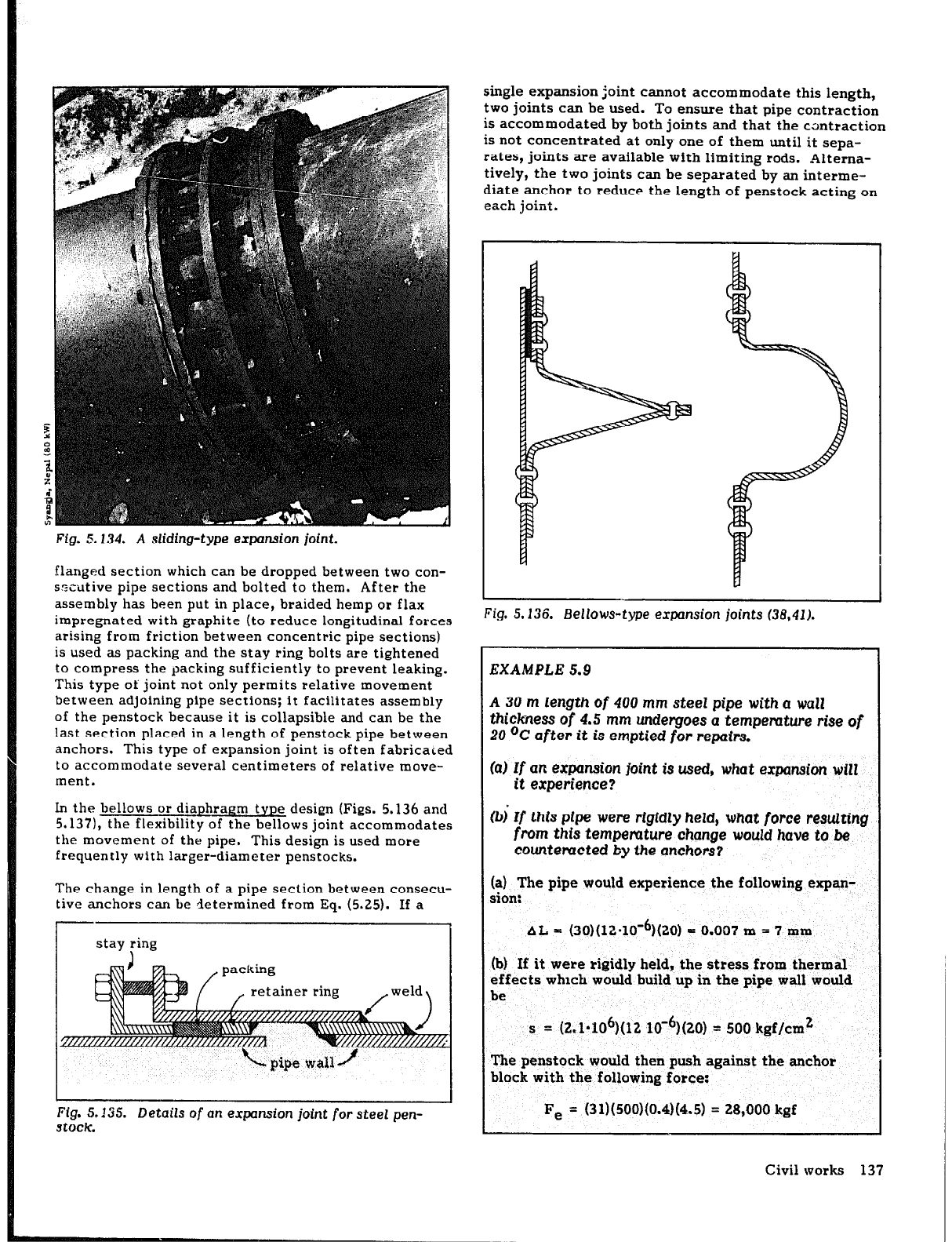
Fig. 5.134. A sliding-type
expansion joint.
flanged section which can be dropped between two con-
szcutive pipe sections and bolted to them. After the
assembly has been put in place, braided hemp or flax
impregnated with graphite (to reduce longitudinal forces
arising from friction between concentric pipe sections)
is used as packing and the stay ring bolts are tightened
to compress the packing sufficiently to prevent leaking.
This type of joint not only permits relative movement
between adjoining pipe sections; it facilitates assembly
of the penstock because it is collapsible and can be the
last section placed in a length of penstock pipe between
anchors. This type of expansion joint is often fabricated
to accommodate several centimeters of relative move-
ment.
In the bellows or diaphragm type design (Figs. 5.136 and
5.137), the flexibility of the bellows joint accommodates
the movement of the pipe. This design is used more
frequently with larger-diameter penstocks.
The change in length of a pipe section between consecu-
tive anchors can be determined from Eq. (5.25). If a
stay :ing
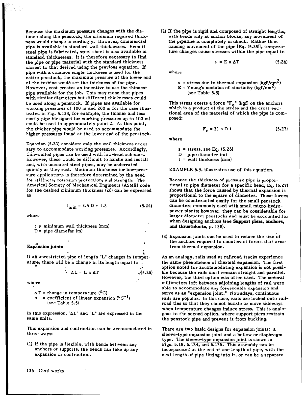
single expansion joint cannot accommodate this length,
two joints can be used. To ensure that pipe contraction
is accommodated by both joints and that the cantraction
is not concentrated at only one of them until it sepa-
rates, joints are available with limiting rods. Altema-
tively, the two joints can be separated by an interme-
diate anchor to reduce the length of penstock acting on
each joint.
Fig. 5.136. Bellows-type expansion
joints (36,41).
EXAMPLE 5.9
A 30 m length of 400 mm steel pipe with a wall
thickness of 4.5
mm undergoes a
tempemture rise of
20 OC
after it is emptied for repairs.
(0) Zf
an expansion joint
is
used, what expansion will
it experience?
0, Zf this pipe were rigidly held,
what
force resulting
from
this
temperature change
would have
to be
countemcted by the anchors?
(a) The pipe would experience the following expan-
sion:
AL = (30)(12*10’6)(20) = 0.007 m = 7 mm
(b) If it were rigidly held, the stress from thermal
effects which would build up in the pipe wall would
be
s = (2.1*106)(12 lo-9(20) = 500 kgf/cm2
The penstock would then push against the anchor
block with the following force:
Fe = (31)(500)(0.4)(4.5) = 28,000 kgf
Civil works 137
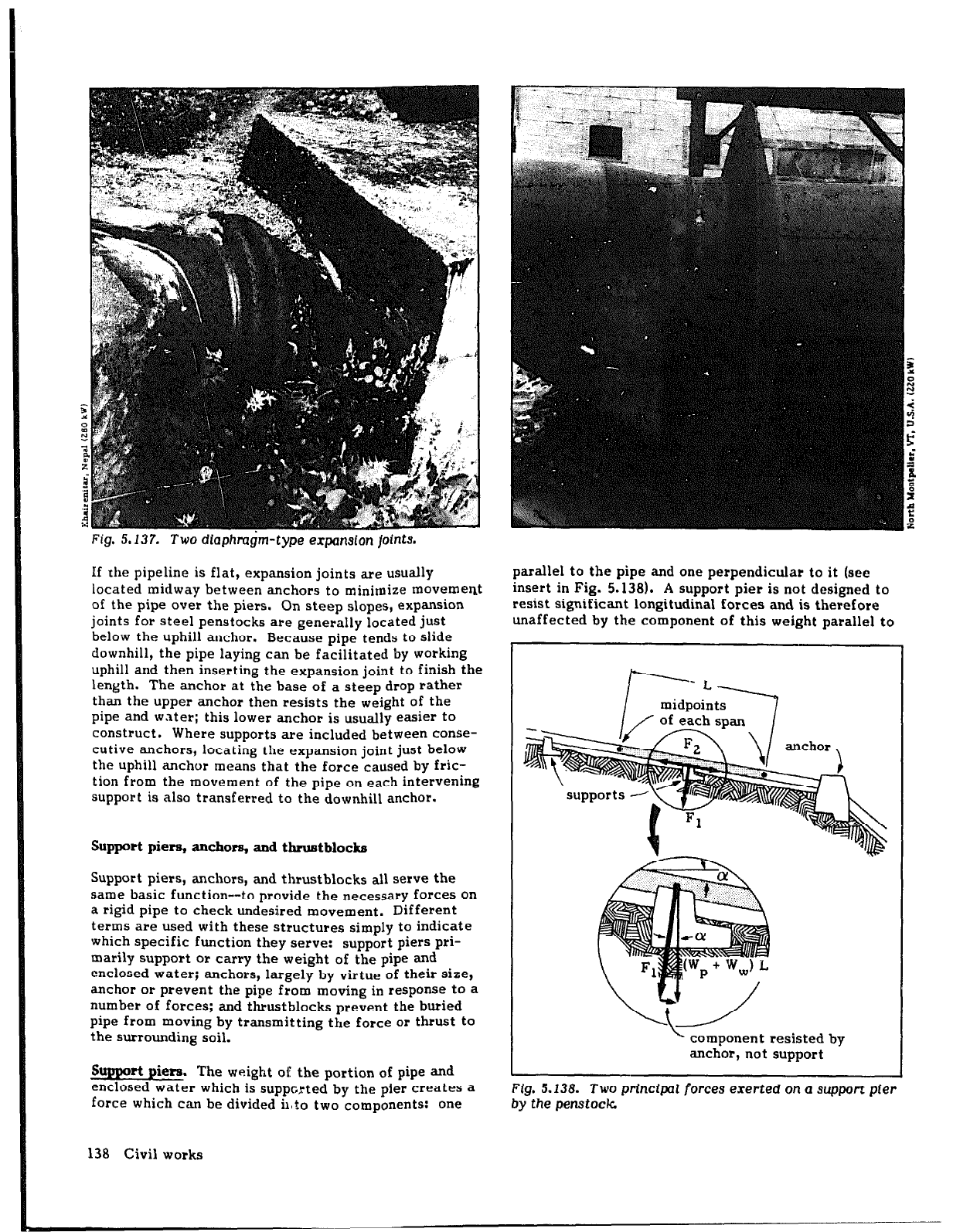
Fig. 5.137. Two dlaphm$m-type expansion
joints.
If the pipeline is flat, expansion joints are usually
located midway between anchors to minimize movement
of the pipe over the piers. On steep slopes, expansion
joints for steel penstocks are generally located just
below the uphill anchor. Because pipe tends to slide
downhill, the pipe laying can be facilitated by working
uphill and then inserting the expansion joint to finish the
length. The anchor at the base of a steep drop rather
than the upper anchor then resists the weight of the
pipe and water; this lower anchor is
usually
easier to
construct. Where supports are included between conse-
cutive anchors, locating the expansion joint just below
the uphill anchor means that the force caused by fric-
tion from the movement of the pipe on each intervening
support is also transferred to the downhill anchor.
Support piers, anchors, and tbrustblocks
Support piers, anchors, and thrustblocks all serve the
same basic function--to provide the necessary forces on
a rigid pipe to check undesired movement. Different
terms are used with these structures simply to indicate
which specific function they serve: support piers pri-
marily support or carry the weight of the pipe and
enclosed water; anchors, largely by virtue of their size,
anchor or prevent the pipe from moving in response to a
number of forces; and thrustblocks prevent the buried
pipe from moving by transmitting the force or thrust to
the surrounding soil.
sUPPC& pie=. The weight of the portion of pipe and
enclosed water which is supported by the pier creates a
force which can be divided il,to two components: one
parallel to the pipe and one perpendicular to it (see
insert in Fig. 5.138). A support pier is not designed to
resist significant longitudinal forces and is therefore
unaffected by the component of this weight parallel to
k component resisted by
anchor, not support
Fig. 5.138. Two principal forces exerted on Q support pier
by the penstock
138 Civil works
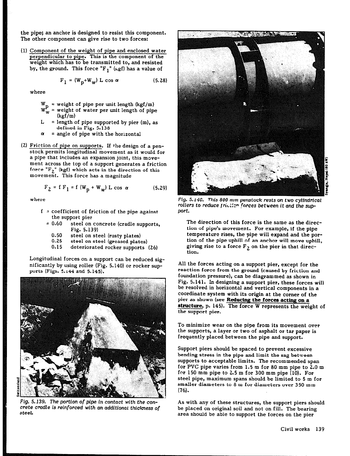
the pipe; an anchor is designed to resist this component.
The other component can give rise to two forces:
(1) Component of the weight of pipe and enclosed water
perpendicular to pipe. This is the component of the
weight which has to be transmitted to, and resisted
by, the ground. This force “Fl” (hgf) has a value of
F1 = (Wp+Ww) L cos u
(5.28)
where
W
= weight of pipe per unit length (kgf/m)
wpw= weight of water per unit length of pipe
(kgf/m)
L
= length of pipe supported by pier (m), as
defined in Fig. 5.138
Q
= angle of pipe with the horizontal
(2) Friction of pipe on supports. If the design of a pen-
stock permits longitudinal movement as it would for
a pipe that includes an expansion joint, this move-
ment across the top of a support generates a friction
force “F2”
(kgf) which acts in the direction of this
movement. This force has a magnitude
F2 = f Fl = f (W, + Ww) L cos a
where
f = coefficient of friction of the pipe against
the support pier
= 0.60
steel on concrete (cradle supports,
Fig. 5.139)
0.50
steel on steel (rusty plates)
0.25
steel on steel (greased plates)
0.15 deteriorated rocker supports (26)
Longitudinal forces on a support can be reduced sig-
nificantly by using roller (Fig. 5.140) or rocker sup-
ports (Figs. 5.
144 and 5.145).
Fig. 5.139.
The portion of pipe in contact with
the con-
crete cmdle is reinforced
with an
additional thickness of
steel.
Fig.
5.140. This 800 mm penstock rests
on two
cylindrical
rollers
to
reduce
~ri~;!z?
forces between
it and the
sup-
port.
The direction of this
force
is the same as the direc-
tion of pipe’s movement. For example, if the pipe
temperature rises, the pipe will expand and the por-
tion of the pipe uphill of an anchor will move uphill,
giving rise to a force F2 on the pier in that direc-
tion.
All the forces acting on a support pier, except for the
reaction force from the ground (caused by friction and
foundation pressure), can be diagrammed as shown in
Fig. 5.141. In designing a support pier, these forces will
be resolved in horizontal and vertical components in a
coordinate system with its origin at the corner of the
pier as shown (see Reducing the forces acting on a
&ructure, p. 145). The force W represents the we<ght of
the support pier.
To minimize wear on the pipe from its movement over
the supports, a layer or two of asphalt or tar paper is
frequently placed between the pipe and support.
Support piers should be spaced to prevent excessive
bending stress in the pipe and limit the sag between
supports to acceptable limits. The recommended span
for PVC pipe varies from 1.5 m for 80 mm pipe to 2.0 m
for 150 mm pipe to 2.5 m for 300 mm pipe (IO). For
steel pipe, maximum spans should be limited to 5 m for
smaller diameters to 8 m for diameters over 350 mm
(76).
As with any of these structures, the support piers should
be placed on original soil and not on fill. The bearing
area should be able to support the forces on the pier
Civil works 139