Inversin R. Allen Micro-hydropower Sourcebook
Подождите немного. Документ загружается.

In ordei not to exceed this pressure, the minimum area
“A” (m ) of the vent inlet is given by the following
equation:
A=
Q
400 cfi
(5.33)
where
Q = flow of air through inlet (m3/s) (see below)
C = coefficient of discharge through inlet
= 0.5 for ordinary air-inlet valves
0.7 for short air-inlet pipes (38)
To cover the wotse possible case, the maximum air flow
“Q” through a vent should equal the maximum flow of
water the turbine can accommodate. EXAMPLE 5.12
illustrates use of these equations. .
The vent pipe should be long enough so that its opening
to the atmosphere is above the high-water level in the
fotebay (see Fig. 5.21); otherwise, a high-water level in
the forebay will cause water to flow out the vent, possi-
bly inundating the area and undermining the forebay
or
penstock.
Powerhouses
In the first part of this chapter, it was noted that a
powerhouse is constructed to enclose and protect the
turbo-generating and associated equipment. This sec-
tion briefly reviews some factors which should be con-
sidered in designing such a structure.
A powerhouse needs a floor area only sufficient to
accommodate the equipment and permit easy access on
all sides for installation, maintenance, and repair. The
door to the powerhouse should be large enough to permit
passage of the largest piece of equipment. When large
and heavy turbo-generating machinery is to be used, the
building should be high enough to accommodate a hoist
or
other equipment which is used to assemble ot disas-
semble the machinery.
To handle heavy equipment at large plants, cranes which
travel on overhead rails supported by the powerhouse
superstructure are often used. For micro-hydropower
schemes, a hoist
or
b!ock and tackle, temporarily sup-
potted from a beam, is more commonly used for heavy
equipment. In these cases, the loads to be supported
govern the structural design of the powerhouse walls.
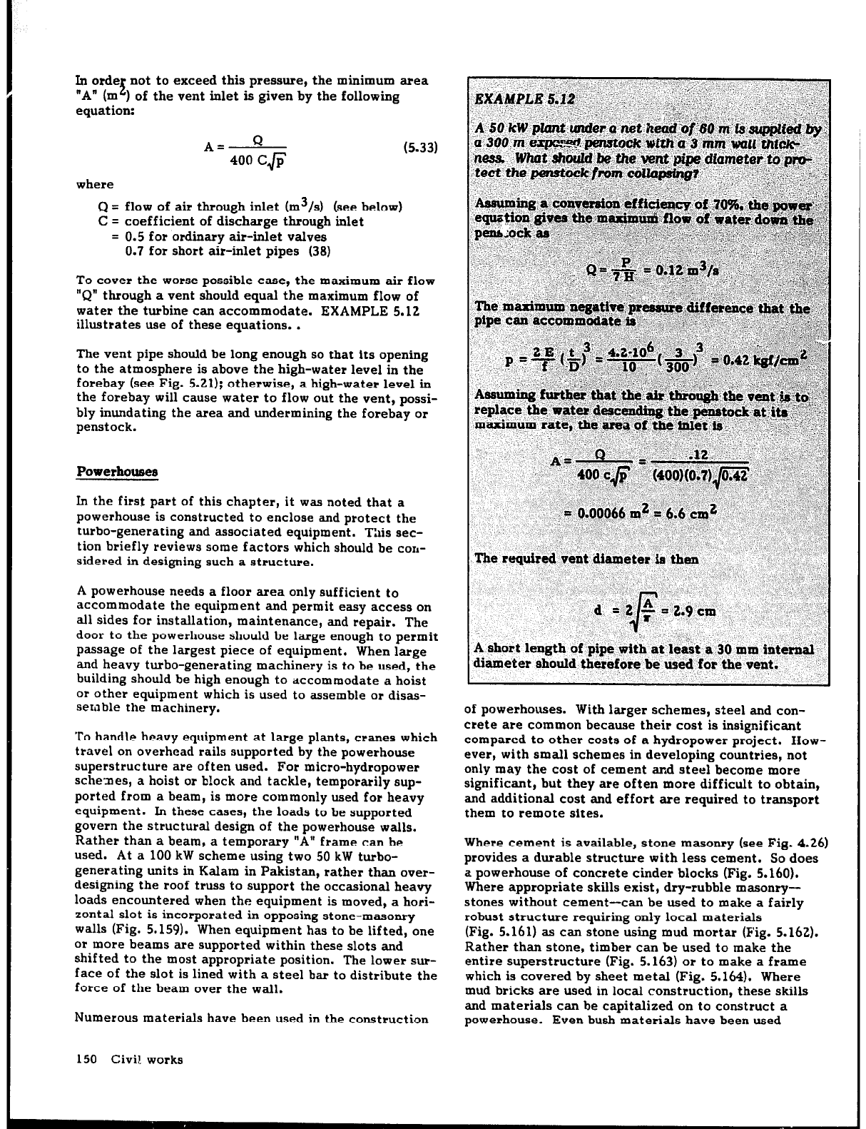
Rather than a beam, a temporary “A” frame can be
used. At a 100 kW scheme using two 50 kW turbo-
generating units in Kalam in Pakistan, rather than over-
designing the roof truss to support the occasional heavy
loads encountered when the equipment is moved, a hori-
zontal slot is incorporated in opposing stone-masonry
walls (Fig. 5.159). When equipment has to be lifted, one
ot more beams are supported within these slots and
shifted to the most appropriate position. The lower sur-
face of the slot is lined with a steel bar to distribute the
force of the beam over the wall.
Numerous materials have been used in the construction
150 Civil. works
of powerhouses. With larger schemes, steel and con-
crete ate common because their cost is insignificant
compared to other costs of a hydropower project. How-
ever, with small schemes in developing countries, not
only may the cost of cement and steel become mote
significant, but they ate often mote difficult to obtain,
and additional cost and effort are required to transport
them to remote sites.
Where cement is available, stone masonry (see Fig. 4.26)
provides a durable structure with less cement. So does
a powerhouse of concrete cinder blocks (Fig. 5.160).
Where appropriate skills exist, dry-rubble masonry-
stones without cement-can be used to make a fairly
robust structure requiting only local materials
(Fig. 5.161) as can stone using mud mortar (Fig. 5.162).
Rather than stone, timber can be used to make the
entire superstructure (Fig. 5.163) ot to make a frame
which is coveted by sheet metal (Fig. 5.164). Where
mud bricks ate used in local construction, these skills
and materials can be capitalized on to construct a
powerhouse. Even bush materials have been used
,&oof truss
Fig. 5.:59. Slots
in opposing
walls
of a powerhouse support
a beam used to support heavy machinery during its assem-
bly or disassembly.
Fig.
5.160. A
small powerhorcse
constructed of cinder
blocks.
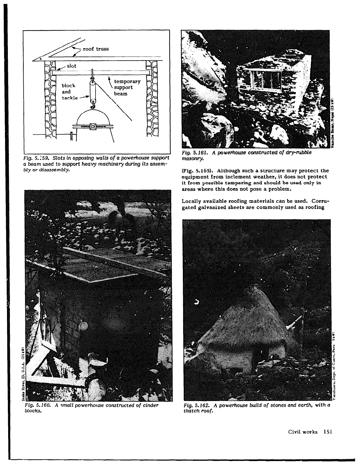
Fig. 5.161. A powerhouse constructed
of
dry-rubble
masonry.
(Fig. 5.165). Although such a structure may protect the
equipment from inclement weather, it does not protect
it from possible tampering and should be used only in
areas where this does not pose a problem.
Locally available roofing materials can be used. Corru-
gated galvanized sheets are commonly used as roofing
Fig. 5.162. A powerhouse builrl
of stones
and earth,
with a
thatch
roof.
Civil works 151
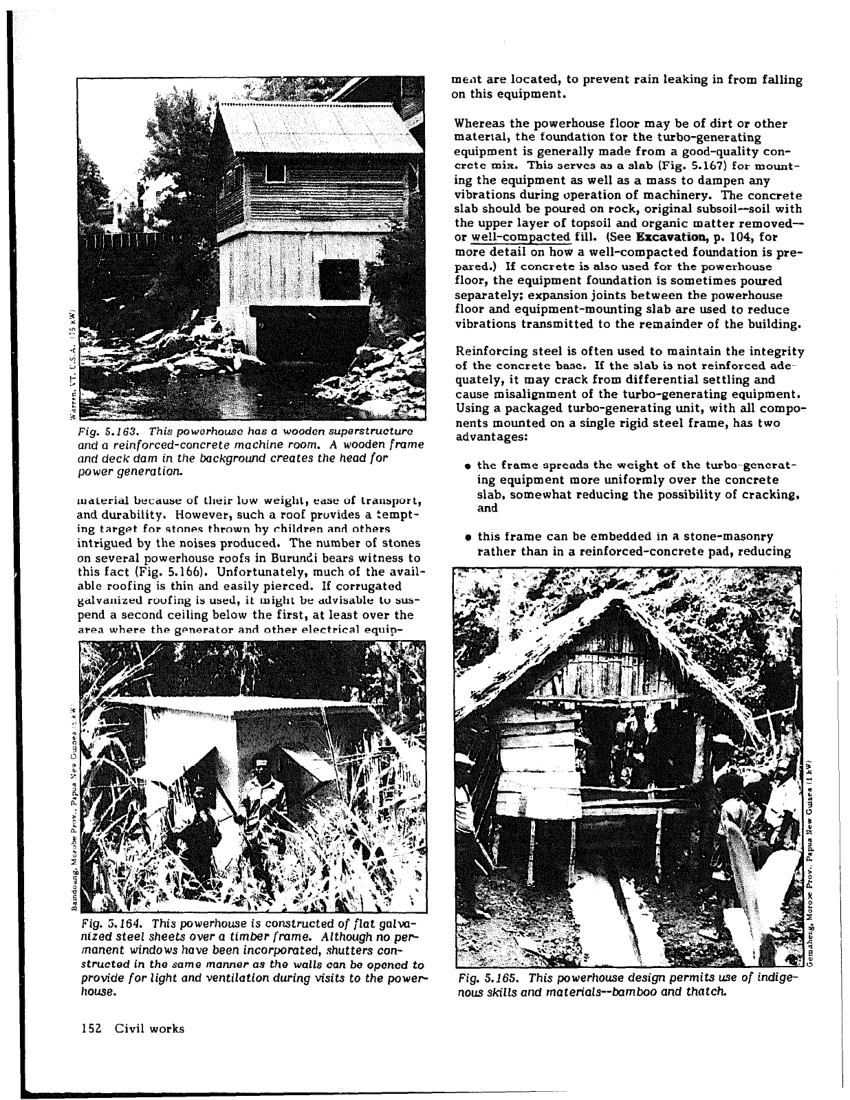
Fig. 5.163. This powerhouse
has
a wooden superstructure
and a reinforced-concrete
machine room. A wooden frame
and deck dam in the background creates the
head for
power
generation.
material because of their low weight, ease of transport,
and durability. However, such a
roof
provides a tempt-
ing target for stones thrown by children and others
intrigued by the noises produced. The number of stones
on several powerhouse roofs in Burundi bears witness to
this fact (Fig. 5.166). Unfortunately, much of the avail-
able roofing is thin and easily pierced. If corrugated
galvanized roofing is used, it might be advisable to sus-
pend a second ceiling below the first, at least over the
area where the generator and other electrical equip-
Fig. Zi.164. This powerhouse is constructed of flat galva-
nired steel
sheets over a
timber frame. Although
no per-
manent windows have been incorpomted, shutters con-
structed in the same manner as the walls can be opened to
provide for
light and
ventilation during visits to the power-
house.
ment are located, to prevent rain leaking in from falling
on this equipment.
Whereas the powerhouse floor may be of dirt or other
material, the foundation for the turbo-generating
equipment is generally made from a good-quality con-
crete mix. This serves as a slab (Fig. 5.167) for mount-
ing the equipment as well as a mass to dampen any
vibrations during operation of machinery. The concrete
slab should be poured on rock, original subsoil-soil with
the upper layer of topsoil and organic matter removed--
or we!l-compacted fill. (See
Excavation,
p. 104, for
more detail on how a well-compacted foundation is pre-
pared.) If concrete is also used for the powerhouse
floor, the equipment foundation is sometimes poured
separately; expansion joints between tbe powerhouse
floor and equipment-mounting slab are used to reduce
vibrations transmitted to the remainder of the building.
Reinforcing steel is often used to maintain the integrity
of the concrete base. If the slab is not reinforced ade-
quately, it may crack from differential settling and
cause misalignment of the turbo-generating equipment.
Using a packaged turbo-generating unit, with all compo-
nents mounted on a single rigid steel frame, has two
advantages:
m the frame spreads the weight of the turbo-generat-
ing equipment more uniformly over the concrete
slab, somewhat reducing the possibility of cracking,
and
e this frame can be embedded in a stone-masonry
rather than in a reinforced-concrete pad, reducing
Fig. 5.165. This powerhouse design permits use
of
indige-
nous skills and materials--bamboo and thatch.
152 Civil works
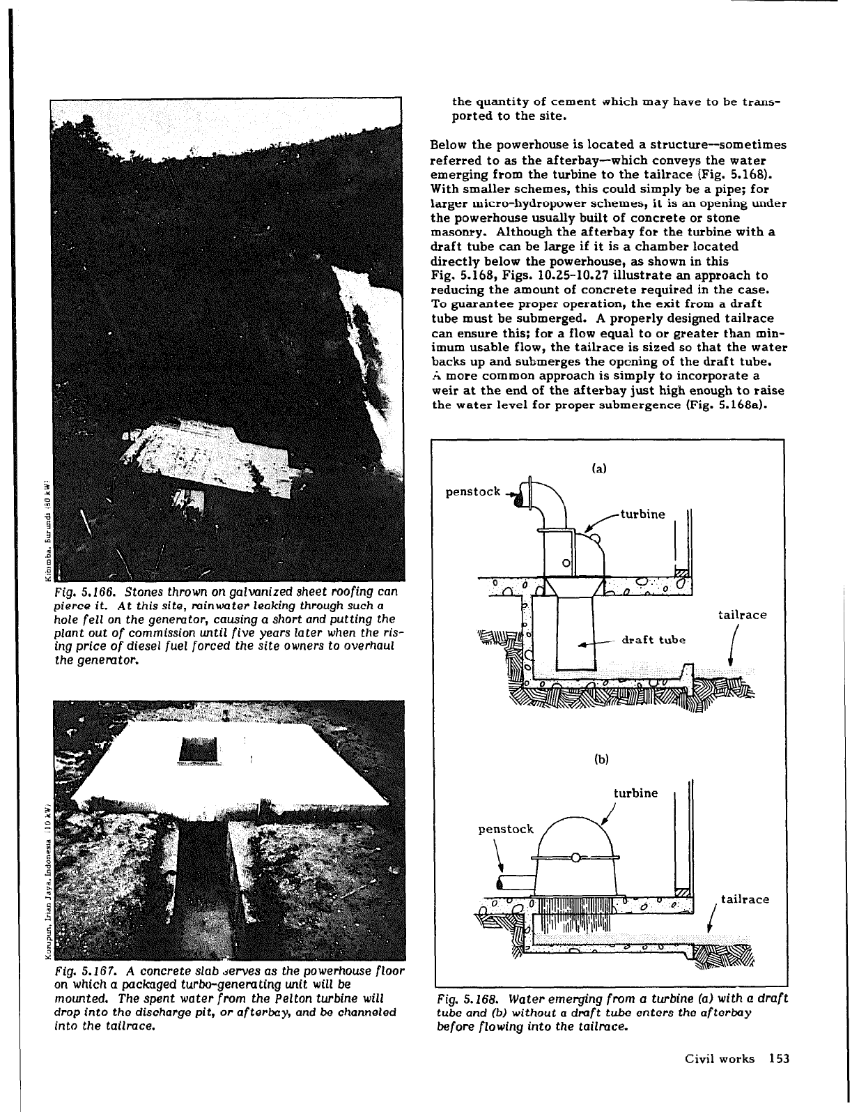
Fig. 5. f66.
Stones
thrown on galvanized sheet roofing
can
pierce it. At this
site,
minwater leaking through such a
hole
fell on the
genemtor, causing a short and putting the
plant
out of
commission until five
years
later
when the ris-
ing
price
of diesel fuel
forced the site owners
to overhaul
the genemtor.
Fig. 5.167. A concrete slab derves as the powerhouse floor
on which a pa&aged turbo-genemting unit will be
mounted. The spent water from
the
Pelton turbine
will
drop into
the
discharge pit,
or afterbay,
and be channeled
into the tailmce.
the quantity of cement .vhich may have to be trans-
ported to the site.
Below the powerhouse is located a structure-sometimes
referred to as the afterbay-which conveys the water
emerging from the turbine to the tailrace (Fig. 5.168).
With smaller schemes, this could simply be a pipe; for
larger micro-hydropower schemes, it is an opening under
the powerhouse usually built of concrete or stone
masonry. Although the afterbay for the turbine with a
draft tube can be large if it is a chamber located
directly below the powerhouse, as shown in this
Fig. 5.168, Figs. 10.25-10.27 illustrate an approach to
reducing the amount of concrete required in the case.
To guarantee proper operation, the exit from a draft
tube must be submerged. A properly designed tailrace
can ensure this; for a flow equal to or greater than min-
imum usable flow, the tailrace is sized so that the water
backs up and submerges the opening of the draft tube.
.& more common approach is simply to incorporate a
weir at the end of the afterbay just high enough to raise
the water level for proper submergence (Fig. 5.168a).
penstock
(a)
tailrace
turbine
i
tailrace
/
Fig. 5.168.
Water emerging
from a turbine
(aI with a draft
tube and (b) without
a draft tube enters the after&y
before flowing
into
the
tailmce.
Civil works 153
Several other features should be considered in the
design of a powerhouse:
o High ambient temperatures are found in many coun-
tries. In addition, the heat produced by losses in a
generator also increases the temperature in a
powerhouse. Because high temperatures reduce
generator life, adequate ventilation is required. For
micro-hydropower plants, louvers and roof vents
provide adequate ventilation.
a For reasons of safety, the powerhouse floor should
be kept dry. Adequate floor drainage should be
incorporated to remove any water resulting from
leaks, condensation, rain, etc.
e To minimize overhead obstructions, power and con-
trol cables should be placed in conduits in floor
trenches.
m Before the power leaves the powerhouse, a tap
should be included to provide power for lighting-
indoors as well as possibly outdoors-and electric
outlets or power points.
Other components
Gates and valves
Gates and valves control the flow through water con-
veyance structures. Numerous types are in use. For
micro-hydropower schemes, this discussion is limited to
stoplogs and sliding gates and butterfly and gate valves.
Gates are generally used for control of flow through
--
open passageways or for other low-pressure applica-
tions. Sliding gates--also referred to as vertical lift
gates or sluice gates-are used where there is a :red to
adjust fairly frequently the flow through an openi;++
Stoplogs are not usually used to adjust the flow, but to
stop it completely from time to time, such as when
maintenance or repair work is needed downstream.
Valves are used to control the flow through a pipe.
For micro-hydropower applications, they control flow
through Ihe penstock, usually at the base of the pen-
stock-as a turbine isolation valve to permit uncoupling
of the turbine and the penstock--and occasionally at the
inlet to the penstock. Gate valves are often more read-
ily available, but butterfly valves are increasing in
popularity.
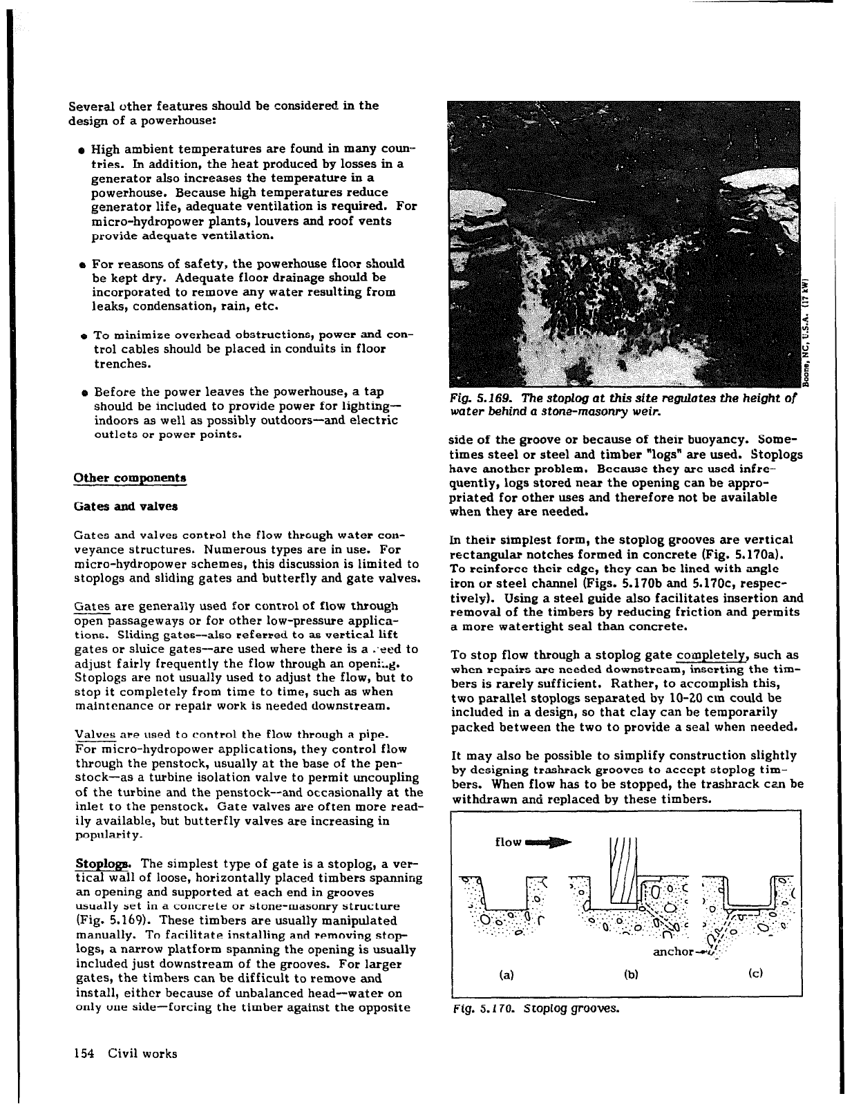
Stoplogs. The simplest type of gate is a stoplog, a ver-
tical wall of loose, horizontally placed timbers spanning
an opening and supported at each end in grooves
usually set in a concrete or stone-masonry structure
(Fig. 5.169). These timbers are usually manipulated
manually. To facilitate installing and removing stop-
logs,
a narrow platform spanning the opening is usually
included just downstream of the grooves. For larger
gates, the timhers can be difficult to remove and
install, either because of unbalanced head-water on
only one side-forcing the timber against the opposite
154 Civil works
Fig. 5.169. The stoplog at this site regulates the height
of
water
behind
a
stone-masonry weir.
side of the groove or because of their buoyancy. Some-
times steel or steel and timber “logs” are used. Stoplogs
have another problem. Because they are used infre-
quently, logs stored near the opening can be appro-
priated
for
other uses and therefore not be available
when they are needed.
In their simplest form, the stoplog
grooves
are vertical
rectangular notches formed in concrete (Fig. 5.170a).
To reinforce their edge, they can be lined with angle
iron
or
steel channel (Figs. 5.170b and 5.17Oc, respec-
tively). Using a steel guide also facilitates insertion and
removal of the timbers by reducing friction and permits
a more watertight seal than concrete.
To stop flow through a stoplog gate completely, such as
when repairs are needed downstream, inserting the tim-
bers is rarely sufficient. Rather, to accomplish this,
two parallel stoplogs separated by lo-20 cm could be
included in a design, so that clay can be temporarily
packed between the two to provide a seal when needed.
It may also he possible to simplify construction slightly
by designing trashrack grooves to accept stoplog tim-
bers. When flow has to be stopped, the trashrack can be
withdrawn and replaced by these timbers.
(a)
(b)
Fig. 5.170. Stoplog grooves.
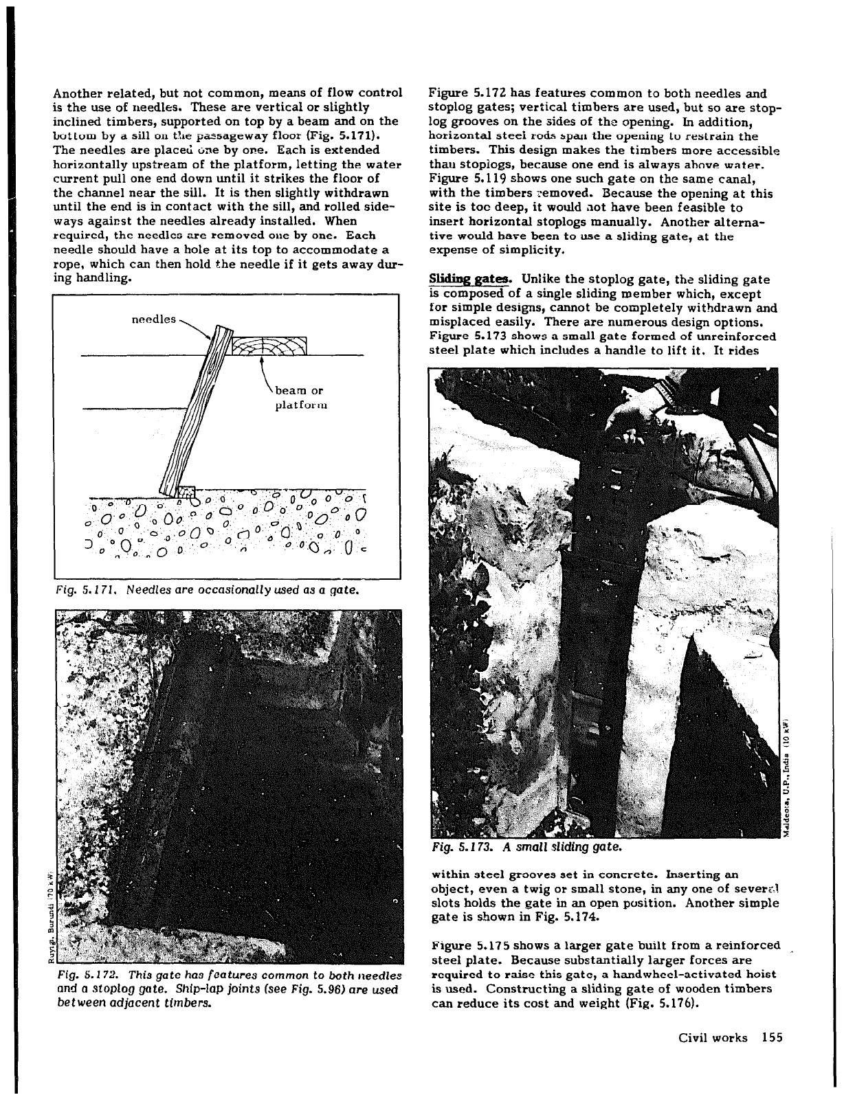
Another related, but not common, means of flow control
is the use of needles. These are vertical or slightly
inclined timbers, supported on top by a beam and on the
bottom by a sill on the passageway floor (Fig. 5.171).
The needles are place6 irne by one. Each is extended
horizontally upstream of the platform, letting the water
current pull one end down until it strikes the floor of
the channel near the sill. It is then slightly withdrawn
until the end is in contact with the sill, and rolled side-
ways against the needles already installed. When
required, the needles are removed one by one. Each
needle should have a hole at its top to accommodate a
rope, which can then hold the needle if it gets away dur-
ing handling.
Fig.
S.172. This gate has
features common to both needles
and a
stoplog gate.
Ship-lap joints (see Fig. 5.96) are used
between adjacent
timbers.
Figure 5.172 has features common to both needles and
stoplog gates; vertical timbers are used, but so are stop-
log grooves on the sides of the opening. In addition,
horizontal steel
rods
span the opening to restrain the
timbers. This design makes the timbers more accessible
thau stoplogs, because one end is always above water.
Figure 5.119 shows one such gate on the same canal,
with the timbers Temoved. Because the opening at this
site is tot deep, it would aot have been feasible to
insert horizontal stoplogs manually. Another altema-
tive would have been to use a sliding gate, at the
expense of simplicity.
. .
SlldlDgga tes.
Unlike the stoplog gate, the sliding gate
% composed of a single sliding member which, except
for simple designs, c¬ becompletely withdrawn and
misplaced easily. There are numerous design options.
Figure 5.173 shows a small gate formed of unreinforced
steel plate which includes a handle to lift it. It rides
Fig. 5.173. A small sliding gate.
within steel grooves set in concrete. Inserting an
object, even a twig or small stone, in any one of sever?.1
slots holds the gate in an open position. Another simple
gate is shown in Fig. 5.174.
Figure 5.175 shows a larger gate built from a reinforced
steel plate. Because substantially larger forces are
required to raise this gate, a handwheel-activated hoist
is used. Constructing a sliding gate of wooden timbers
can reduce its cost and weight (Fig. 5.176).
Civil works 155
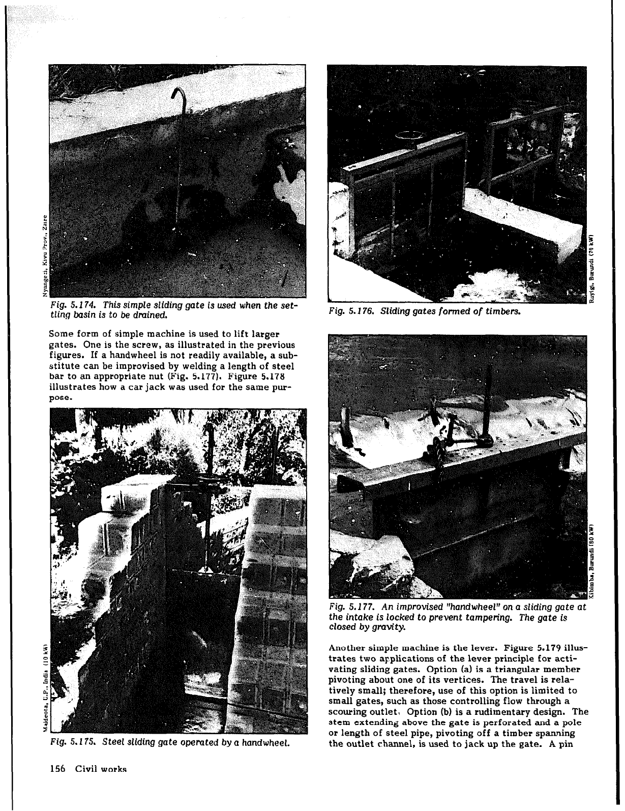
Fig.
5.174.
This simple sliding gate is used when the set-
tling basin is to be dmined.
Some form of simple machine is used to lift larger
gates. One is the screw, as illustrated in the previous
figures. If a handwheel is not readily available, a sub-
stitute can be improvised by welding a length of steel
bar to an appropriate nut (Fig. 5.177). Figure 5.178
illustrates how a car jack was used for the same pur-
pose.
Fig. 5.175.
Steel
sliding
gate
operated by a handwheel.
156 Civil works
Fig. 5.176.
Sliding gates
formed
of timbers.
Fig. 5.177. An improvised “handwheel” on a sliding gate
at
the intake is locked to prevent tampering. The gate is
closed by gravity.
Another simple machine is the lever. Figure 5.179 illus-
trates two applications of the lever principle for acti-
vating sliding gates. Option (a) is a triangular member
pivoting about one of its vertices. The travel is rela-
tively small; therefore, use of this option is limited to
small gates, such as those controlling flow through a
scouring outlet, Option (b) is a rudimentary design. The
stem extending above the gate is perforated and a pole
OP
length of steel pipe, pivoting off a timber spanning
the outlet channel, is used to jack up the gate. A pin
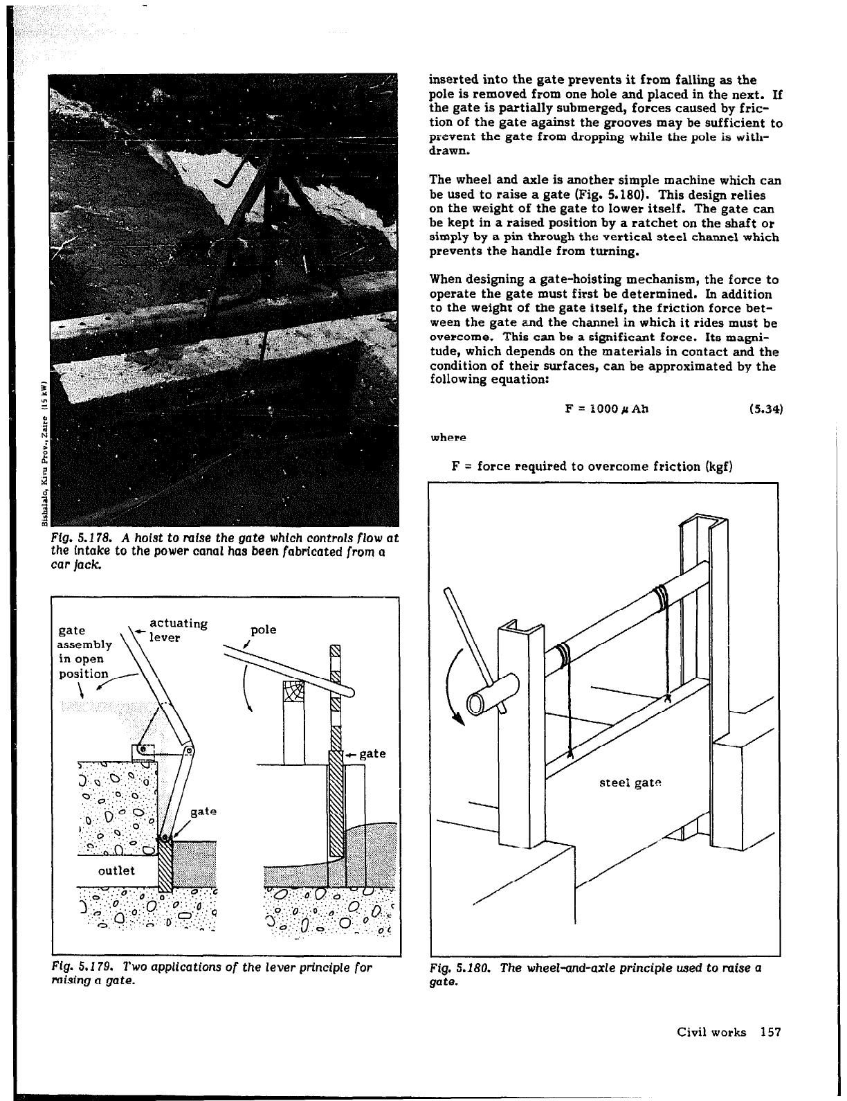
Fig. 5.178. A
hoist to raise the
gate
which controls flow
at
the Intake to the power canal has been fabricated from a
car
jack.
ing
pole
outlet
inserted
into the gate prevents it from falling as the
pole is removed from one hole and placed in the next. If
the gate is partially submerged, forces caused by fric-
tion of the gate against the grooves may be sufficient to
prevent the gate from dropping while the pole is with-
drawn.
The wheel and axle is another simple machine which can
be used to raise a gate (Fig. 5.180). This design relies
on the weight of the gate to lower itself. The gate can
be kept in a raised position by a ratchet on the shaft or
simply by a pin through the vertical steel channel which
prevents the handle from turning.
When designing a gate-hoisting mechanism, the force to
operate the gate must first be determined. In addition
to the weight of the gate itself, the friction force bet-
ween the gate and the channel in which it rides must be
overcome, This can be a significant force. Its magni-
tude, which depends on the materials in contact and the
condition of their surfaces, can be approximated by the
following equation:
F = 1000fiAh
(5.34)
where
F = force required to overcome friction (kgf)
Fig. 5.180.
The wheel-and-axle
principle used to raise a
gate.
Civil works 157
= coefficient of static friction. (see Table 5.8)
i = submerged area of gate
(m2)
h = distance from water surface to center of A (m)
The valves of “,e” given in Table 5.8 are fOF smooth-fin-
ished suFfaces. Ferrous materials subject to rusting
may develop excessive friction from pitting and the
accumulation of rust when they are exposed to succes-
sive wetting and drying. If a gate is closed for long
periods of time, the valves of “p* for metal on metal
should be incteased by 50% (38). JIven though steel on
steel should not be used for normally closed gates,
because they are likely to rust closed, steel is still
widely used at micro-hydropower sites because of its
strength, availability, and low cost. Using wood for at
least one of the surfaces avoids these problems.
Surface
coefficient
of friction
steel on bronze
0.45
Steel on steel
0.60
Wood on metal
1.0
Wood on wood 1.1
Rubber on wood
1.1
The actual force encountered in raising a gate is the
sum of the friction force described above and the
weight of the submerged gate. If a timber gate is used,
the buoyancy of the submerged timbers will offset the
weight of the gate to some degree.
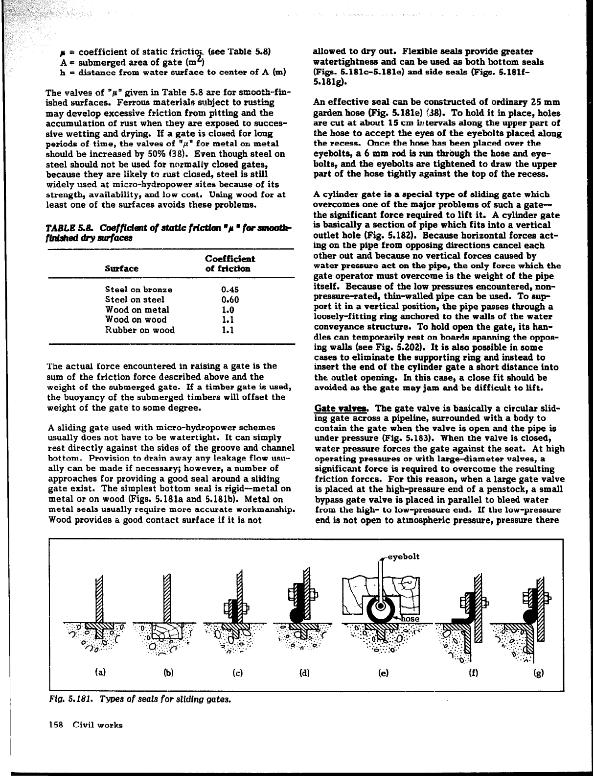
A sliding gate used with miCFO-hydFOpOWeF schemes
usually does not have to be Watertight. It can simply
rest directly against the sides of the groove and channel
bottom. Provision to drain away any leakage flow usu-
ally can be made if necessary; however, a number of
approaches for providing a good seal around a sliding
gate exist. The simplest bottom seal is rigid-metal on
metal OF on wood (Figs. 5.181a and 5.181b). Metal on
metal seals usually require more accurate workmanship.
Wood provides a good contact surface if it is not
allowed to dry out. Flexible seals provide greater
watertightness and can be used as both bottom seals
(Figs. 5.181c-5.181e) and side seals (Figs. 5.181f-
5.181g).
An effective seal can be constructed of ordinary 25 mm
garden hose (Fig. 5.1814 C38). To hold it in place, holes
are cut at about 15 cm ir: tervals along the upper part of
the hose to accept the eyes of the eyebolts placed along
the recess. Once the hose has been placed over the
eyebolts, a 6 mm rod is nm tbrbugh the hose and eye-
bolts, and the eyebolts are tightened to draw the upper
part of the hose tightly against the top of the recess.
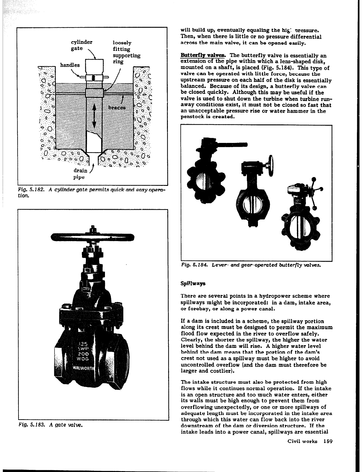
A cylinder gate is a special type of sliding gate which
overcomes one of the major problems of such a gate-
the significant force required to lift it. A cylinder gate
is basically a section of pipe which fits into a vertical
outlet hole (Fig. 5.182). Because horizontal forces act-
ing on the pipe from opposing directions cancel each
other out and because no vertical forces caused by
water pressure act on the pipe, the only
force
which the
gate operator must overcome is the weight
of the
pipe
itself. Because of the low pressures encountered, non-
pressure-rated, thin-walled pipe can be used. To sup-
port it in a vertical position, the pipe passes through a
loosely-fitting ring anchored to the walls of the water
conveyance structure. To hold open the gate, its han-
dles can temporarily rest on boards spanning the oppos:
ing walls (see Fig. 5.202). It is also possible in some
cases to eliminate the supporting
ring
and instead to
insert the end of the cylinder gate a short distance into
the outlet opening. In this case, a close fit should be
avoided as the gate may jam and be difficult to lift.
Gate valta. The gate valve is basically a circular slid-
ing gate across a pipeline, surrounded with a body to
contain the gate when the valve is open and the pipe is
under pressure (Fig. 5.183). When the valve is closed,
water pressure forces the gate against the seat. At high
operating pressures or with large-diameter valves, a
significant force is required to overcome the resulting
friction forces. FOF this reason, when a large gate valve
is placed at the high-pressure end of a penstock, a small
bypass gate valve is placed in parallel to bleed water
from the high- to low-pressure end. If the low-pressure
end is not open to atmospheric pressure, pressure there
1 (a) lb)
(cl
Id)
(4
Fig. 5.181.
Types
of
seals
for
sliding gates.
158 Civil works
cylinder
gate
\
loosely
fitting
supporting
drain /
pipe
‘ig. 5.182. A cylfnder gate permits quick and easy opem-
1 I
rlon.
Fig. 5.183.
A
gate wk.
will build up, eventually equaling the hi&: oressure.
Then, when there is little or no pressure differential
across the main valve, it can be opened easily.
Butte valves. The butterfly valve is essentially an
extension of the pipe within which a lens-shaped disk,
mounted on a shaft, is placed (Fig. 5.184). This type of
valve can be operated with little force, because the
upstream pressure on each half of the disk is essentially
balanced. Because of its design, a butterfly valve can
be closed quickly. Although this may be useful if the
valve is used to shut down the turbine when turbine run-
away conditions exist, it must not be closed so fast that
an unacceptable pressure rise or water hammer in the
penstock is created.
ig.
5.184. Lever-
and geapopemted butterfly wives.
spillways might be incorporated: in a dam, intake area,
or forebay,
or
along a power canal.
If a dam is included in a scheme, the spillway portion
along its crest must be designed to permit the maximum
flood flow expected in the river to overflow safely.
Clearly, the shorter the spillway, the higher the water
level behind the dam will rise. A higher water level
behind the dam means that the portion of the dam’s
crest not used as a spillway must be higher to avoid
uncontrolled overflow (and the dam must therefore be
larger and costlier).
The intake structure must also be protected from high
flows while it continues normal operation. If the intake
is an open structure and too much water enters, either
its walls must be high enough to prevent them from
overflowing unexpectedly, or one or more spillways of
adequate length must be incorporated in the intake area
through which this water can flow back into the river
downstream of the dam or diversion structure. If the
intake leads into a power canal, spillways are essential
Civil works 159