Inversin R. Allen Micro-hydropower Sourcebook
Подождите немного. Документ загружается.

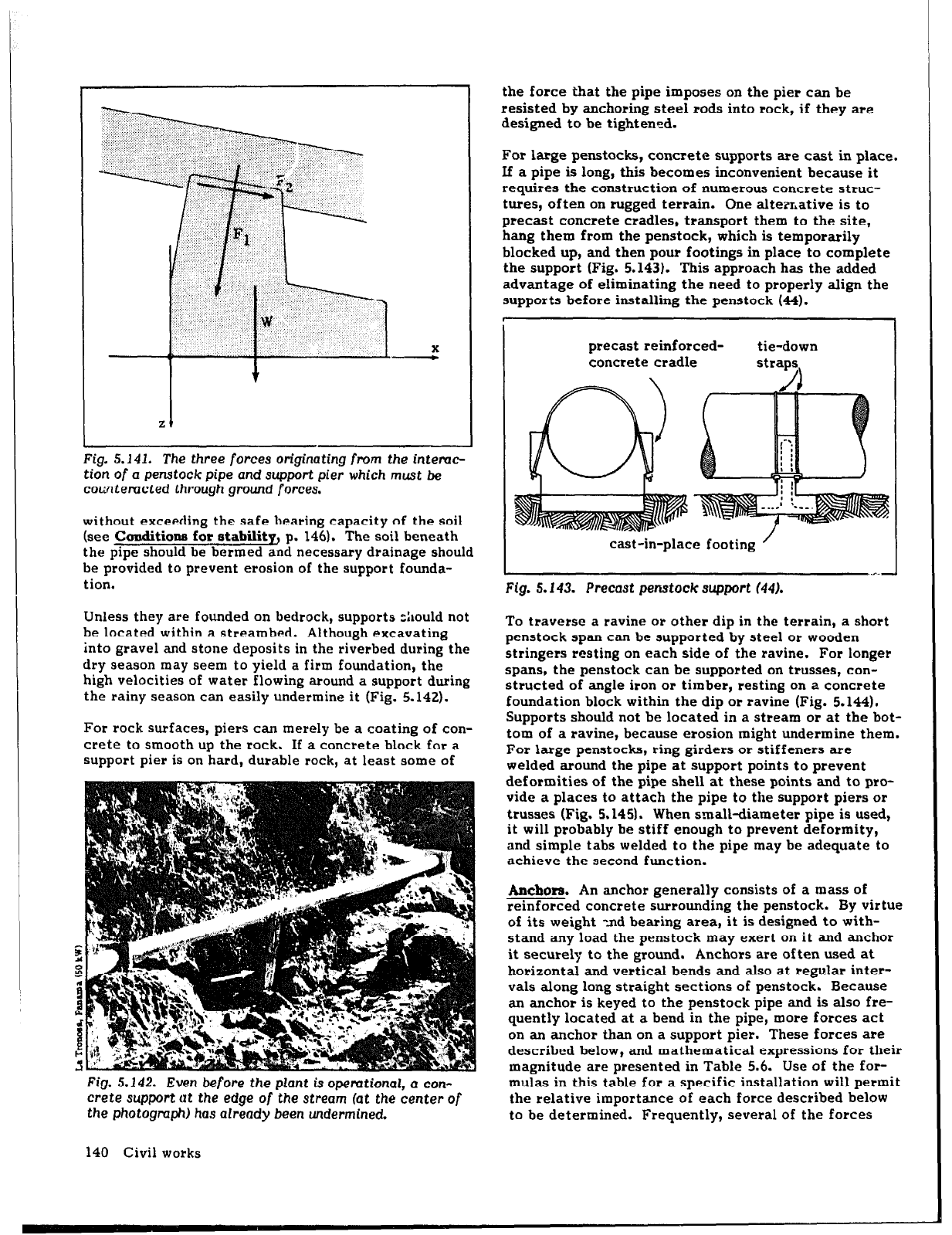
Fig. 5.141. The three
forces
originating
from
the
intemc
tion of a
penstock
pipe and support pier which
must be
cowtemcted
through
ground
forces.
without exceeding the safe bearing capacity of the soil
(see Conditione for stability, p. 146). The soil beneath
the pipe should be bermed and necessary drainage should
be provided to prevent erosion of the support founda-
tion.
Unless they are founded on bedrock, supports c:lould not
be located within a streambed. Although excavating
into gravel and stone deposits in the riverbed during the
dry season may seem to yield a firm foundation, the
high velocities of water flowing around a support during
the rainy season can easily undermine it (Fig. 5.142).
For rock surfaces, piers can merely be a coating of con-
crete to smooth up the rock. If a concrete block for a
support pier is on hard, durable rock, at least some of
Fig, 5.142. Even before
the
plant is
operational, a con-
crete support at the edge of the stream
fat the
center of
the photograph) has already been undermined.
the force that the pipe imposes on the pier can be
resisted by anchoring steel rods into rock, if they are
designed to be tightened.
For large penstocks, concrete supports are cast in place.
If a pipe is long, this becomes inconvenient because it
requires the construction of numerous concrete struc-
tures, often on rugged terrain. One alternative is to
precast concrete cradles, transport them to the site,
hang them from the penstock, which is temporarily
blocked up, and then pour footings in place to complete
the support (Fig. 5.143). This approach has the added
advantage of eliminating the need to properly align the
supports before installing the penstock (44).
precast reinforced-
concrete cradle
tie-down
straps,
cast-in-place footing
/
Fig. 5.143. Precast penstock support (44).
To traverse a ravine or other dip in the terrain, a short
penstock span can be supported by steel or wooden
stringers resting on each side of the ravine. For longer
spans, the penstock can be supported on trusses, con-
structed of angle iron or timber, resting on a concrete
foundation block within the dip or ravine (Fig. 5.144).
Supports should not be located in a stream or at the bot-
tom of a ravine, because erosion might undermine them.
For large penstocks, ring girders or stiffeners are
welded around the pipe at support points to prevent
deformities of the pipe shell at these points and to pro-
vide a places to attach the pipe to the support piers or
trusses (Fig. 5.145). When small-diameter pipe is used,
it will probably be stiff enough to prevent deformity,
and simple tabs welded to the pipe may be adequate to
achieve the second function.
Anchors. An anchor generally consists of a mass of
reinforced concrete surrounding the penstock. By virtue
of its weight -nd bearing area, it is designed to with-
stand any load the penstock may exert on it and anchor
it securely to the ground. Anchors are often used at
horizontal and vertical bends and also at regular inter-
vals along long straight sections of penstock. Because
an anchor is keyed to the penstock pipe and is also fre-
quently located at a bend in the pipe, more forces act
on an anchor than on a support pier. These forces are
described below, and mathematical expressions for their
magnitude are presented in Table
5.6.
Use of the fot-
mulas in this table
for
a specific installation will permit
the relative importance of each force described below
to be determined. Frequently, several of the forces
140 Civil works
Fig. 5. f44. This support, which
has the same clxmcteris-
tics as a rocker support, permits the penstock to traverse
irregular terrain while avoiding bends in the pipe.
stiffener or support rings
,A---
/’
/
r--II
column
support
rocker
pivot
described below can be disregarded because they are
insignificant or nonexistent.
(1) Component of the weight of pipe and enc!osed water
.-
perpendicular to pipe. This force is analogous to
force “Fl”
acting on supports. Because there may be
a bend at the anchor, however, both the upstream
and downstream lengths of pipe contribute sepa-
rately, each force perpendicular to the center-
line of the pipe segment which contributes to it.
Figure 5.146 illustrates only the contribution from
the upstream length. It should be noted that the
force that results from the parallel component of
the weight of these lengths
of
pipe is included in
force “F4”.
(2) Friction of pipe on supports. If the penstock moves
longitudinally over support piers, a friction force on
the pipe is created at each support as described in
Support piers (p. 138). A force “F2”, equal to the
sum of all these forces but opposite in direction,
acts on the anchor (Fig. 5.147). This force exists
only where one
or
more support piers are located
between the anchor and an expansion joint. For
example, if an expansion joint is located just down-
hill of the anchor, friction forces on the dow’nhill
length of pipe will not be transmitted to the anchor
from that side.
(3) Hydrostatic pressure within a bend. The hydrostatic
pressure within the water in a bend creates a forr,t
“F3” which acts outward as shown in Fig. 5.148 (or
inward if the bend is concave upward). This is a
major force which must be considered in designing
anchors or thrustblocks for medium- and high-head
schemes, but it can be minimized by avoiding signi-
ficant, discreie bends along the penstock alignment,
such as by using gradual curves along a plastic pen-
stock.
Fig. 5. I45. A simplified representation of a typical
rocker
support.
Fig.
5.146. The uphill portion
of
the
pipe span is
shown
contributing a force normal to
its
centerline.
Civil works 141
TABLE 5.6.
The mag~ffufe of Uw force3 vhf& may he encomtered fn desff@q an anchor
Source Magnitde kf)
Direction
(1) Component of weight of pipe
and water perpendicular
20
pipe
F1 = (Wp + Ww) L’ cos P **
(2) Friction of pipe on supports
F2 = f (W
P
+ Ww) L” cos a **
(3) Hydrostatic pressure of bend B-a
F3 = 1.6.103 p D2 sin(T)
‘-.
---+
I
(4) Component of weight of pipe
4
I
F4 = Wp L sin a
**
parallel to pipe
I
(5) Thermally induced stresses (if
----4!
:.:
no expansion joints included)
F5 = 31 D t E a AT
I
I\...
*
(6) Friction within expansion joint
F6 = 3.1 D c
----a!
I
(7) Hydrostatic pressure on
exposed end
of
pipe in
expansion joint
(8) Dynamic pressurt? at bends
F7=3.1pDt
B-a
F8 = 250 (Q/D)’ sin( 2)
(9) Reduction in pipe diameter
Fq = 1.0.103 p A”
* Direction of forces shown for expanding pipe; reverse directions if pipe is contracting.
** Replace a by fi for contribution to force from downstream penstock section.
a = coefficient of linear expansion of pipe (OC-‘)
(see Table 5.5)
A” = reduction of pipe area at pipe reduction (m2)
= upstream pipe area - downstream pipe area
C = friction in expansion joint per unit length of
circumference (kgf/m)
D = pipe diameter (m)
E
= (Young’s) modulus of elasticity (kgf/cm’)
(see Table 5.5)
f
= coefficient of friction between pipe and support
piers (see Support piers, p. 138)
L = length defined in Fig. 5.149 (m)
L’ = length defined in Fig. 5.146 (m)
L”
= length defined in Fig. 5.147 (m)
P
= hydrostatic pressure (including surge pressure) at
point of interest (m)
142 Civil works
Q = flow (m”/s)
t
= penstock wall thickness (mm)
AT = maximum temperature change pipe will experience
(OC)
Wp = weight of pipe per unit length (kgf/m)
W,= weight of water per unit pipe length (kgf/m)
bisector of angle
formed by pipes
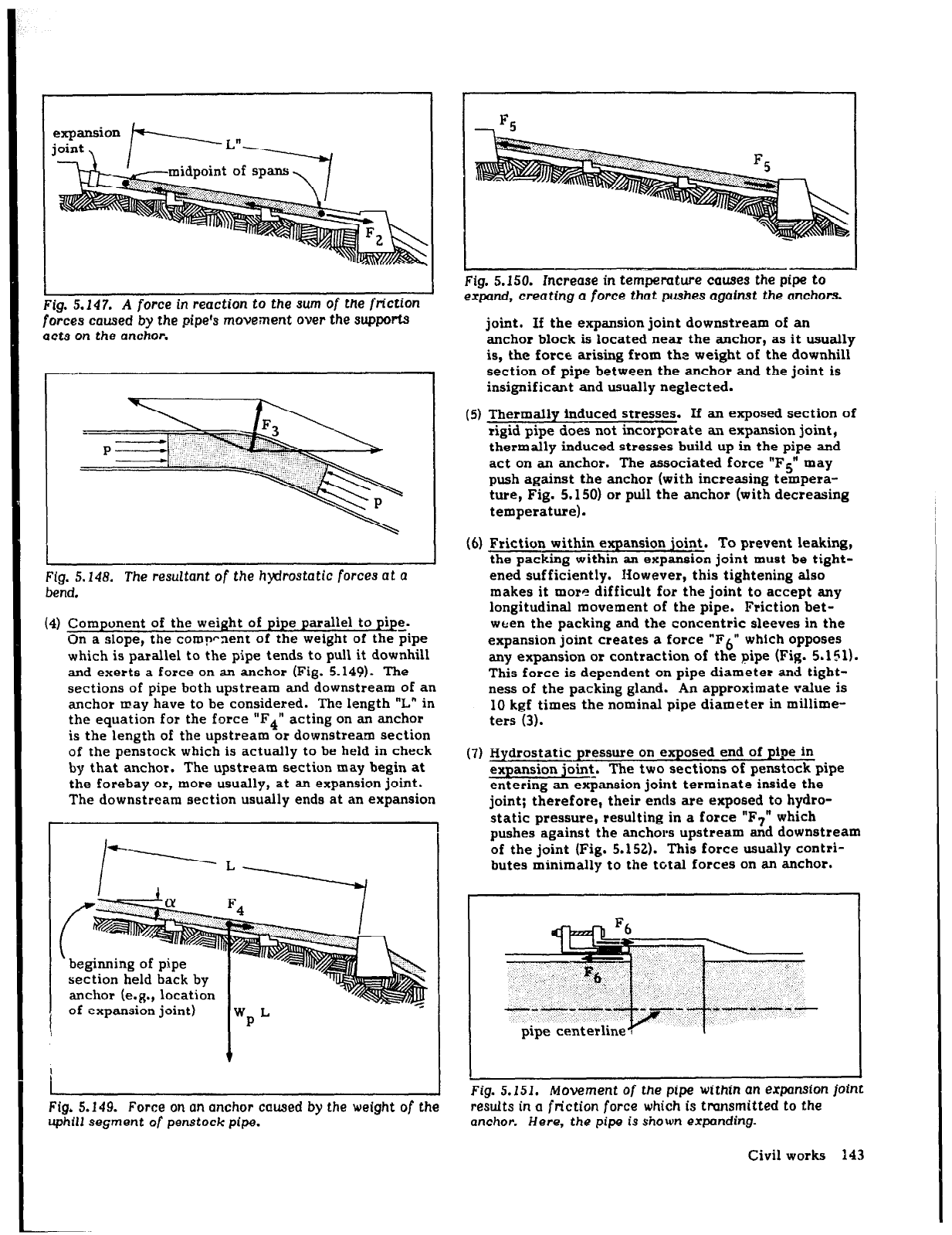
Fig. 5.147. A
force in
reaction to the
sum
of the friction
forces caused
by the
Pipe% movement over the supportS
acts
on the
anchor.
Fig. 5.148. The resultant of the hydrostatic forces at
a
bend.
(4) Component of the weight of pipe parallel to pipe.
On a slope, the comprnent of the weight of the pipe
which is parallel to the pipe tends to pull it downhill
and exerts a force on an anchor (Fig. 5.149). The
sections of pipe both upstream and downstream of an
anchor may have to be considered. The length “L” in
the equation for the force “F4” acting on an anchor
is the length of the upstream or downstream section
of the penstock which is actually to be held in check
by that anchor. The upstream section may begin at
the forebay or, more usually, at an expansion joint.
The downstream section usually ends at an expansion
’ beginning of pipe
section held back by
anchor (e.g., location
.s
1
of expansion joint)
wP L
+
I
Fig. 5.149. Force on an anchor caused by the weight of the
uphill
segment
of penstock
pipe.
Fig. 5.150. Increase in temperature causes
the
pipe to
expand, creating
a force that pushes against the anchors.
joint. If the expansion joint downstream of an
anchor block is located near the anchor, as it usually
is, the force arising from the weight of the downhill
section of pipe between the anchor and the joint is
insignificant and usually neglected.
(5) Thermally induced stresses. If an exposed section of
rigid pipe does not incorporate an expansion joint,
thermally induced stresses build up in the pipe and
act on an anchor. The associated force “F5” may
push against the anchor (with increasing tempera-
ture, Fig. 5.150) or pull the anchor (with decreasing
temperature).
(6) Friction within expansion joint. To prevent leaking,
the packing within an expansion joint must be tight-
ened sufficiently. However, this tightening also
makes it more difficult for the joint to accept any
longitudinal movement
of
the pipe. Friction bet-
ween the packing and the concentric sleeves in the
expansion joint creates a force “F6” which opposes
any expansion or contraction
of
the pipe (Fig. 5.151).
This force is dependent on pipe diameter and tight-
ness of the packing gland. An approximate value is
IO kgf times the nominal pipe diameter in millime-
ters (3).
(7) Hydrostatic pressure on exposed end of pipe in
expansion joint, The two sections of penstock pipe
entering an exptansion joint terminate inside the
joint; therefore, their ends are exposed to hydro-
static pressure, resulting in a force “F7” which
pushes against the anchors upstream and downstream
of the joint (Fig. 5.152). This force usually contri-
butes minimally to the total forces on an anchor.
Fig. 5.151. Movement
of
the pipe within an expansion
joint
results in a friction
force
which is transmitted to the
anchor. Ilere, the pipe is shown expanding.
Civil works 143
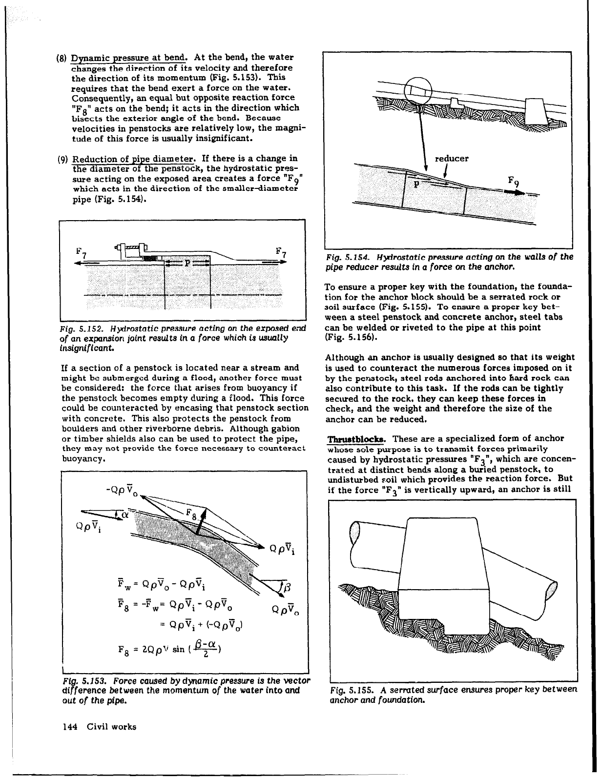
(8) Dynamic pressure at bend. At the bend, the water
changes the direction of its velocity and therefore
the direction of its momentum (Fig. 5.153). This
requires that the bend exert a force on the water.
Consequently, an equal but opposite reaction force
“Fg” acts on the bend; it acts in the direction which
bisects the exterior angle of the bend. Because
velocities in penstocks are relatively low, the magni-
tude of this force is usually insignificant.
(9) Reduction of pipe diameter. If there is a change in
the diameter of the penstock, the hydrostatic pres-
sure acting on the exposed area creates a force “F9”
which acts in the direction of the smaller-diameter
pipe (Fig. 5.154).
Fig. 5.152. Hydrostatic
pressure
acting
on the exposed end
of
an expansion
joint
remAt.
in a force which is usually
Insignificant.
If a section of a penstock is located near a stream and
might be submerged during a flood, another force must
be considered: the force that arises from buoyancy if
the penstock becomes empty during a flood. This force
could be counteracted by encasing that penstock section
with concrete. This also protects the penstock from
boulders and other riverbome debris. Although gabion
or timber shields also can be used to protect the pipe,
they may not provide the force necessary to counteract
buoyancy.
P, =
-Fw= Qpvi - QpTo
= Qpvi + (-Qp’j,)
F8 =
2QpV
sin ( 2
B-ul)
Ffg. 5.153. Force caused by
dynamic
pressure is the vector
difference between the momentum of the water into and
out of
the pipe.
\ reducer
Fig.
5.154.
Hydrostatic
pressure
acting
on the walls
of
the
pipe reducer results
in a force on the
anchor.
To ensure a proper key with the foundation, the founda-
tion for the anchor block should be a serrated rock or
soil surface (Fig. 5.155). To ensure a proper key bet-
ween a steel penstock and concrete anchor, steel tabs
can be welded or riveted to the pipe at this point
(Fig. 5.156).
Although an anchor is usually designed so that its weight
is used to counteract the numerous forces imposed on it
by the penstock, steel rods anchored into hard rock can
also contribute to this task. If the rods can be tightly
secured
to the rock, they can keep these forces in
check, and the weight and therefore the size of the
anchor can be reduced.
‘Ihru&bIocks. These are a specialized form of anchor
whose sole purpose is to transmit forces primarily
caused by hydrostatic pressures “F3”, which are concen-
trated at distinct bends along a buried penstock, to
undisturbed soil which provides the reaction force. But
if the force “F3
” is vertically upward, an anchor is still
Fig. 5.155. A sermted surface ensures
proper key between
anchor and
fowIdation.
144 Civil works
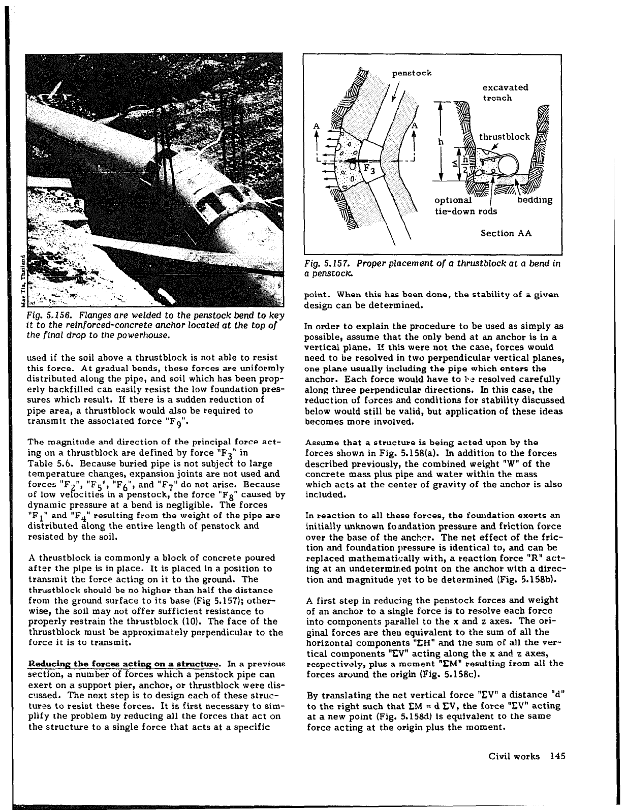
Fig. 5.156. Flanges are welded to the penstock bend to key
it
to
the
reinforced-concrete anchor located
at
the top
of
the final drop to the powerhouse.
used if the soil above a thrustblock is not able to resist
this force. At gradual bends, these forces are uniformly
distributed along the pipe, and soil which has been prop-
erly backfilled can easily resist the low foundation pres-
sures which result. If there is a sudden reduction of
pipe area, a thrustblock would also be required to
transmit the associated force “F9”.
The magnitude and direction of the principal force act-
ing on a thrustblock are defined by force “F3” in
Table 5.6. Because buried pipe is not subject to large
temperature changes, expansion joints are not used and
forces “F
of low
“, “F5”, “F6”, and “F7” do not arise. Because
ve ocities in a penstock, the force “Fs” caused by F
dynamic pressure at a bend is negligible. The forces
“Fl” and “F4” resulting from the weight of the pipe are
distributed along the entire length of penstock and
resisted by the soil.
A thrustblock is commonly a block of concrete poured
after the pipe is
in
place. It is placed in a position to
transmit the force acting on it to the ground. The
thrustblock should be no higher than half the distance
from the ground surface to its base (Fig 5.157); other-
wise, the soil may not offer sufficient resistance to
properly restrain the thrustblock (10). The face of the
thrustblock must be approximately perpendicular to the
force it is to transmit.
Reducing the forces acting on a structure. In a previous
section, a number of forces which a penstock pipe can
exert on a support pier, anchor, or thrustblock were dis-
cussed. The next step is to design each of these struc-
tures to resist these forces. It is first necessary to sim-
plify the problem by reducing all the forces that act on
the structure to a single force that acts at a specific
excavated
trench
tie-down rods
Section AA
Fig. 5.157. Proper placement
of
a thrustblock at a bend in
a penstock
point. When this has been done, the stability of a given
design can be determined.
In order to explain the procedure to be used as simply as
possible, assume that the only bend at an anchor is in a
vertical plane. If this were not the case, forces would
need to be resolved in two perpendicular vertical planes,
one plane usually including the pipe which enters the
anchor. Each force would have to bc resolved carefully
along three perpendicular directions. In this case, the
reduction of forces and conditions for stability discussed
below would still be valid, but application of these ideas
becomes more involved.
Assume that a structure is being acted upon by the
forces shown in Fig. 5.158(a). In addition to the forces
described previously, the combined weight “W” of the
concrete mass plus pipe and water within the mass
which acts at the center of gravity of the anchor is also
included.
In reaction to all these forces, the foundation exerts an
initially unknown foundation pressure and friction force
over the base of the anchor. The net effect of the fric-
tion and foundation pressure is identical to, and can be
replaced mathematically with, a reaction force “R” act-
ing at an undetermined point on the anchor with a direc-
tion and magnitude yet to be determined (Fig. 5.158bl.
A first step in reducing the penstock forces and weight
of an anchor to a single force is to resolve each force
into components parallel to the x and z axes. The ori-
ginal forces are then equivalent to the sum of all the
horizontal components “EIi” and the sum of all the ver-
tical components ‘ZV” acting along the x and z axes,
respectively, plus a moment “EM” resulting from all the
forces around the origin (Fig. 5.158~).
By translating the net vertical force “EV” a distance “d”
to the right such that
CM
= d IX, the force ‘?X” acting
at a new point (Fig. 5.1586) is equivalent to the same
force acting at the origin plus the moment.
Civil works 145
(4
(d)
(4
Fig. 5.158. Reducing
a
number of forces
acting
on
a struc-
ture to a single force and a reaction force. The forces in
all five dtagmms ubove are equiwlent.
146 Civil works
The force “ZH” can be moved along its line of action
without contributing any moment. The vector sum of
“XV” and “fH” is the sum of all the forces created by
the penstock and anchor mass, and the reaction force
“R” is equal in magnitude but opposite in direction
(Fig. 5.158e). The reaction force therefore acts at a
distance “d” from the origin of the coordinate system.
A more useful way of expressing the location of the
point at which the reaction force acts is to specify its
distance “e” to the right of the center of the structure’s
base. Therefore, e = d - f/2, where “9” is the length of
the structure’s base. This is referred to as the eccen-
tricity of loading. A negative value of “e” implies a
reaction force acting at the left of the base’s center.
The steps described above are illustrated by applying
them to a specific problem in EXAMPLE 5.10 (p. 148).
coldit.ions for etabilit~ For a support pier or anchor to
be stable and fulfill its intended purpose,
several
condi-
tions must be met:
l
The structure should not slide over its foundation. If
“c” is the coefficient of friction between the pier or
anchor and the ground, the following relationship
must be met for sliding not to occur:
CHliicCV
(5.30)
A value of /r = 0.5 is often assumed initially.
l
The forces acting on the structure should not tend tc.
tip
or
overturn it. If the base of the structure is
rectangular, this condition is met if the resultant
acts within the middle third of the base.
a The load transmitted to the foundation must be
within the safe bearing capacity limit of the founda-
tion material. Because both the structure and foun-
dation are elastic, the foundation pressure usually
is not uniform over the base of the structure.
Although the exact distribution of this pressure is
not known, it is assumed to be a linear distribution
as is indicated in Fig. 5.158a. If the base is rectan-
gular, the maximum and minimum foundation pres-
sures which act at opposite ends of the base, are
then
pf =y (1 f
p,
(5.3 1)
where
A= base area of support pier or anchor (m’)
= length of base (m)
e = eccentricity of loading (m) (see above)
The maximum value of “pf” should be below the safe
bearing capacity limit of the foundation on which
the structure rests. Limits for various soils are
shown in Table 5.7.
Parenthetically, this equation also shows that if the
reaction force on the structure acts outside the mid-
dle third, that is, e > f/6 or e < -l/6, the minimum
TABLE 5.7.
Allouable bearing capacity commonly used by
design engineen
for dfffemt soils (22)
Maximum allowable
bearing pressure (kgf/m’)
0
50,000
lQ0,000
Alluvial soil
Soft clay
Sand
Sand and gravel
Sand and gravel
with clay
Shale
Rock
Because thrustblocks are acted upon primarily by hydro-
static pressure, their stability is ascertained simply by
ensuring that the foundation pressure is within the safe
bearing capacity limit of the soil.
To serve their intended purpose, air valves must permit
an adequate flow of air into the penstock to prevent its
collapse. The smaller the valve opening, the greater
must be the difference between pressure within the
penstock and atmospheric pressure in order to pass a
given air flow. If this difference is too great, the vent
cannot fulfill its purpose and the pipe will still collapse.
The maximum pressure difference which any pipe can
safely accommodate is a function of its thickness-to-
diameter ratio and the material
from
which it has been
constructed, represented by the following expression:
P=
zs(L,’
foundation pressure “pf ” would be negative or under
tension. Clearly, this IS not possible, and the struc-
ture would overturn.
In determining the stability of a structure, the most
adverse cases must be considered, cases in which the
summation of forces or moments is a maximum. The
procedure for assessing the stability of the support pier
analyzed in EXAMPLE 5.10 (p. 148) is illustrated in
EXAMPLE 5.11.
where
p = maximum allowable pressure difference
(kgf/cm2)
E = Young’s modulus of elasticity (kgf/cm2)
(see Table 5.5)
D = penstock diameter at its upper end (any unit of
measure)
t = wall thickness at its upper end (with same units
as D)
I = safety factor = 5 for buried pipe
= 10 for exposed pipe (38)
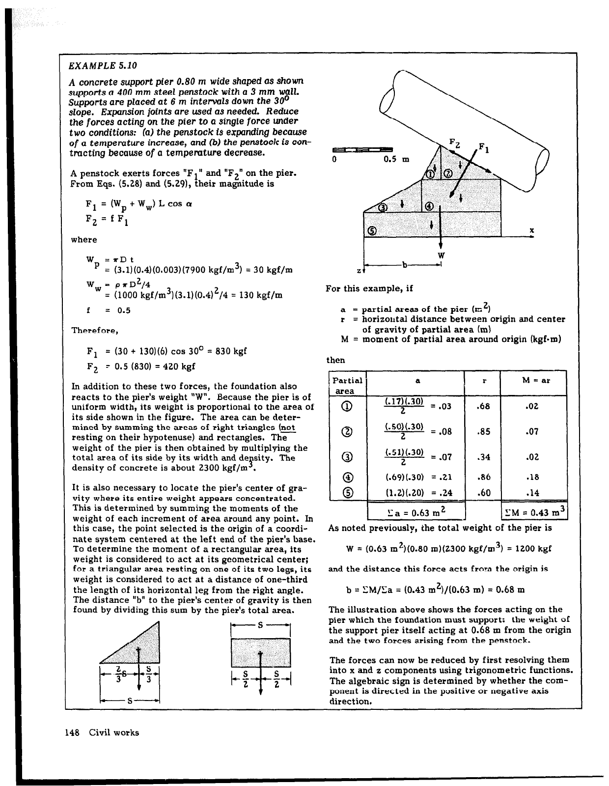
EXAMPLE 5.10
A concrete support pier 0.80 m wide shaped as shown
supports a 400 mm steel penstock with a 3 mm wall.
Supports are placed at 6 m intervals down the 30’
slope. Expansion joints are used as needed. Reduce
the forces acting on
the
pier to a
single force
under
two
conditions: (a) the penstock is expanding because
of a
temperature increase, and (b) the penstock is con-
tracting because
of
a tempemture decrease.
A penstock exerts forces “Fl” and “F2” on the pier.
From Eqs. (5.28) and (5.29), their magnitude is
F1 = (Wp+Ww)Lcoso
F2 = f F1
where
Wp =rDt
= (3.1)(0.4)(0.003)(7900 kgf/m3) = 30 kgf/m
W, = prD2/4
= (1000 kgf/m3)(3.1)(0.4)2/4 = 130 kgf/m
f
= 0.5
Therefore,
Fl
= (30 + 130)(6) cos 30’ = 830 kgf
F2 - 0.5 (830) = 420 kgf
In addition to these two forces, the foundatiun also
reacts to the pier’s weight “W”. Because the pier is of
uniform width, its weight is proportional to the area of
its side shown in the figure. The area can be deter-
mined by summing the areas of right triangles (not
resting on their hypotenuse) and rectangles. The’
weight of the pier is then obtained by multiplying the
total area of its side by its width and de
5
sity. The
density of concrete is about 2300 kgf/m .
It is also necessary to locate the pier’s center of gra-
vity where its entire weight appears concentrated.
This is determined by summing the moments of the
weight of each increment of area around any point. In
this case, the point selected is the origin of a coordi-
nate system centered at the left end of the pier’s base.
To determine the moment of a rectangular area, its
weight is considered to act at its geometrical center;
for a triangular area resting on one of its two legs, its
weight is considered to act at a distance of one-third
the length of its horizontal leg from the right angle.
The distance “b” to the pier’s center of gravity is then
found by dividing this sum by the pier’s total area.
148 Civil works
I-
t
W
b-1
Z
For this example, if
a
= partial areas of the pier (rc’)
r
= horizontal distance between origin and center
of gravity of partial area (m)
M = moment of partial area around origin (kgfmm)
then
Partial
area
0
1
0
0
@
0
a
(.17)(.3(l) = -03
2
(.50)(.30)
= l 08
2
(.51)(.3(l) = V07
2
(.69)(.30)
= l
21
(1.2)(.20) = .24
r
.85
M = ar
l
02
i
.07
.02
.18
.14
La = 0.63 m2 1Z.M = 0.43 m31
As noted previously, the total weight of the pier is
W = (0.63 m2)(0.80 m)(2300 kgf/m3) = 1200 kgf
and the distance this force acts frnrn the origin is
b = \‘M/Sa = (0.43 m2)/(0.63 m) = 0.68 m
The illustration above shows the forces acting on the
pier which the foundation must support: the weight of
the support pier itself acting at 0.68 m from the origin
and the two forces arising from the penstock.
The forces can now be reduced by first resolving them
into x and z components using trigonometric functions.
The algebraic sign is determined by whether the com-
ponent is directed in the positive or negative axis
direction.
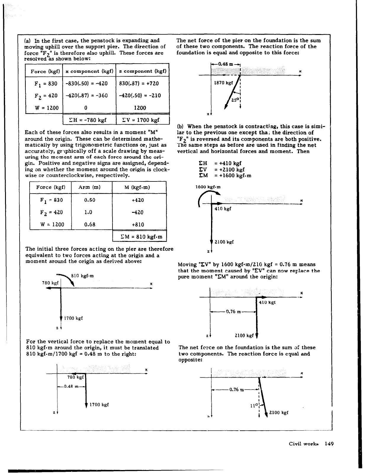
.) In the first case, the penstock is expanding and
oving uphill over the support pier. The direction of
rrce “F2”
is therefore also uphill. These forces are
tsolved as shown below:
The net force of the pier on the foundation is the sum
of these two components. The reaction force of the
foundation is equal and opposite to this force:
Force (kgf) x component (kgf) z component (kgf)
Fl = 830
-830(.50) = -420
830(.87) = +720
F2 = 420 -420(.87) = -360
-420(.50) = -210
w = 1200
0
1200
LH = -780 kgf XV = 1700 kgf
ach of these forces also results in a moment “M”
round the origin. These can be determined mathe-
latically by using trigonometric functions ot, just as
ccurate!y, gt-tphically off a scale drawing by meas-
ring the moment arm of each force around the ori-
in. Positive and negative signs are assigned, depend-
~g on whether the moment around the origin is clock-
(b) When the penstock is contracting, this case is simi-
lar to the previous one except tha; the direction of
“F2” is reversed and its components are both positive.
The same steps as before ate used in finding the net
vertical and horizontal forces and moment. Then
zt
EH
= +410 kgf
EV = +2100 kef
&e ot counterclockwise, respectively.
-
EM = +1600 kgf=m
botce (kgf) [
Arm (ml 1
M
(kgf.m)
F1 = 830
0.50
F2 = 420
1.0
w = 1200
0.68
t420
-420
t810
SM = 810 kgf.m
‘he initial three forces acting on the pier ate therefore
quivalent to two forces acting at the origin and a
lament around the otigin as derived above:
x
---
yor the vertical force to replace the moment equal to
110 kgfom <around the origin, it must be translated
;lO kgf.m/1700 kgf = 0.48 m to the right:
161
410
kgf
Moving “XV” by 1600 kgf*m/ZlO kgf = 0.76 m means
that the moment caused by “IN” can now replace the
pure moment “CM” around the origin:
x
a
410 kg1
I
0.76 m-----r
2 I 2100
kgf 0
The net fcrce
on
the foundation is the sum 3: these
two components. The reaction force is equal and
opposite:
I
x
-0.76 m-1
--
I
Civil works 149