Inversin R. Allen Micro-hydropower Sourcebook
Подождите немного. Документ загружается.

l
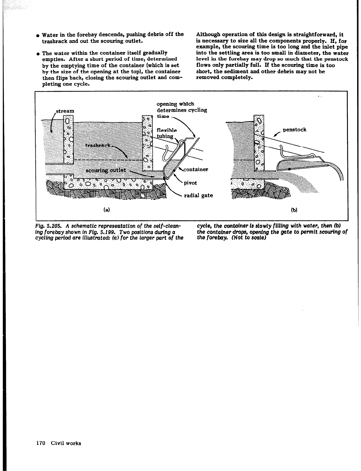
Water in the forebay descends, pushing debris off the
trashrack and out the scouring outlet.
l
The water within the container itself gradually
empties. After a short period of time, determined
by the emptying time of the container (which is set
by the size of the opening at the top), the container
then flips back, closing the scouring outlet and com-
pleting one cycle.
Although operation of this desigu is straightforward, it
is necessary to size all the components properly. If, for
example, the scouring time is too long and the inlet pipe
into the settling area is too small in diameter, the water
level in the forebay may drop so much that the penstock
flows only partially full. If the scouring time is too
short, the sediment and other debris may not be
removed completely.
stream
opening which
determines cycling
(a)
(b)
Fig. 5.205.
A schematIc representation of the self-clean-
cycle,
the
contauter fa slowly fllltng wItn water, then 0
Lng forebay shown in Ftg. 5.199.
Two
positIona durfng a
the container drops, openfng the gate to permit scouring of
cyclfng period are illustrated: la)
for
the larger part of the
the fomt~y. (Not to scale)
170
Civil works
INTRODUCTION
Tine principal motivation for developing a hydropower
site is to generate power. Previous discussions have
focused on selecting an appropriate site and designing
the civil works necessary to convey water to the power-
house. This chapter covers turbines, the machines
which actually convert the energy of water into
mechanical energy.
A variety of types of, and designs for, hydraulic turbines
have heen developed to accomplish the task of extract-
ing power from water under a range of site conditions.
However, most site developers need not be concerned
with the theory of turbine c-poration and the complexi-
ties of turbine design. They must be aware of those
factors necessary for power generation--sufficient
water under pressure to meet their expected load-and
have quantified these parameters. Competent and
experienced firms are then usually relied on to select
the most appropriate turbine to meet the developers’
needs. After the developers have provided the neces-
sary specifications, these firms should be able to select
the appropriate components and ensure their compati-
bility as part of a complete turbine-generator package.
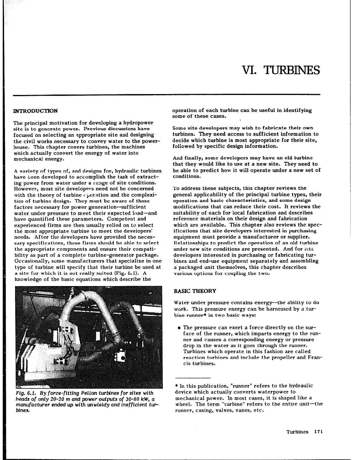
Occasionally, some manufacturers that specialize in one
type of turbine will specify that their turbine be used at
a site for which it is not really suited (Fig. 6.1). A
knowledge of the basic equations which describe the
Fig. 6.1. By force-fltttng
Pslton
turbines
for
sites with
heads of
only 20-30
m and power outputs
of
30-60
kW,
a
manufacturer ended up with unwieldy and inefficient twc
Mnea.
operation of each turbine can be useful in identifying
some of these cases.
-
Some site developers may wish to fabricate their own
turbines. They need access to sufficient information to
decide which turbine is most appropriate for their site,
followed by specific design information.
And finally, some developers may have an old turbine
that they would like to use at a new site. They need to
be able to predict how it will operate under a new set of
conditions.
To address these subjects, this chapter reviews the
general applicability of the principal turbine types, their
operation and basic characteristics, and some design
modifications that can reduce their cost. It reviews the
suitability of each
for
local fabrication and describes
reference materials on their design and fabrication
which are available. This chapter also reviews the spec-
ifications that site developers interested in purchasing
equipment must provide a manufacturer or supplier.
Relationships to predict the operation of an old turbine
under new site conditions are presented. And for ,‘itt
developers interested in purchasing or fabricating tur-
bines and end-use equipment separately and assembling
a packaged unit themselves, this chapter describes
various options for coupling the two.
BASIC THEORY
Water under pressure contains energy--the ability to do
work. This pressure energy can be harxssed by a tur-
bine runner* in two basic ways:
e The pressure can exert a force directly on the sur-
face of the runner, which imparts energy to the run-
ner and causes a corresponding energy or pressure
drop in the water as it goes through the runner.
Turbines which operate in this fashion are called
reaction turbines and include the propeller and Fran-
cis turbines.
* In this publication,
“runner” refers to the hydraulic
device which actually converts waterpower to
mechanical power. In most cases, it is shaped like a
wheel. The term “turbine” refers to the entire unit-the
runner, casing, valves, vanes, etc.
Turbines 17 1
a The pressure can be first converted into kinetic
energy in the form of a high-speed jet of water
emerging from a nozzle. In this case, the pressure
drop occurs across the nozzle. The water in the jet
strikes the runner, imparting its momentum to the
surface it strikes, and then drops into the tailwater
with little remaining energy. Turbines operating in
this manner are called impulse turbines and include
the Pelton, Turgo, and crossflow turbines.
Because the runner of a reaction turbine is ful!y
immersed, the casing around the turbine must be strong
enough to withstand the operating pressures. With an
impulse turbine, the casing serves only to prevent
splashing, to lead the water to the tailrace, and to safe-
guard against accidents.
Careful fabrication is more critical for a reaction tur-
bine, because the pressure drop takes place across its
runner. The clearance between the runner and casing
has to be as small as possible, because any leakage
through this clearance represents a loss of energy.
Because these clearances are small, a reaction turbine
is less tolerant of sediment carried by the water.
Although advantages or disadvantages associated with a
specific turbine type may influence the final choice,
several specific site parameters may still suggest that it
be used:
l
The net head under which a turbine will operate is a
major faxgoverning the selection of a turbine
type. For example, Pelton turbines cannot be used
effectiveiy at low heads, and propeller turbines do
not operate effectively under high heads.
l
The relationship of the required
power
to the head
available at a site also influences the choice of tur-
bine. A Pelton turbine under a head of 30 m could
generate 5 kW, but another turbine type would usu-
ally be selected if 100 kW were required.
l
If the turbine is to operate at a certain speed for
coupling to a generator
or
other machine, this factor
also affects the choice of turbine. For example, for
directly coupling a generator with a turbine operat-
ing under a low head, a reaction turbine would be
required; a Pelton or Turgo runner would turn too
slowly.
All three of t!.ese variables are incorporated in an
expression called the specific speed “Nsn, which is
defined as follows:
Ns =fg
(6.1)
where
N = working speed of turbine (rev/min)
For example, if a turbine that is to generate 90 kW
P = maximum turbine output (hp) = 1.4 x maximum
under a head of 55 m to drive a 1500 rev/min generator
turbine output (kW)
is conventionally selected, it would need a runner with a
H = net head (m)
specific speed
TABLE 6.1.
Spedffc rpeeds for wrlars types of m
Typeofnmner
Pelton
Turgo
Crossflow
Francis
Propeller and Kaplan
%
12-30
20-70
20-80
80-400
340-1000
It should be noted that the metric specific speed
expressed in Eq. (6.1) is 4.45 times the specific speed in
the English system of measurement.
To ascertain which type of
runner
is conventionally used
under conditions found at a proposed site, the appro-
priate plant parameters are substituted into Eq. (6.1) to
determine
its specific speed. Then Table 6.1 is used to
identify which type of runner operates most efficiently
at that specific speed. The values in this table are
baaed on experience gained over the years.
For a Pelton or Turgo rmner with multiple jets, “P” in
Eq. (6.1) represents the power output with one jet in
use. Therefore, it is possible to extend thexge of
efficient operation of both Pelton and Turgo turbines by
equipping them with two or more nozzles. For example,
a Pelton turbine with two nozzles and a runner having a
specific speed
of
12 would generate twice the power at
the same
speed and head as an identical runner with a
single nozzle. From Eq.
(6.11,
it can be seen that this 2-
jet Pelton turbine would be equivalent to a turbine with
a specific speed of 12fl, or 17, because specific speed
is proportional to -li;‘. Pelton turbines equipped with
tao nozzles would therefore operate most efficiently
within the range of specific speeds similar to that for a
single-jet Pelton multiplied by fi, or 17-40. Even in
this case, however, the runner itself is still said to have
a specific speed of 12.
For large hydropower plants, runners are always directly
coupled to t>:i
generator and must therefore be designed
to
run
at tb.e speed
of
the generator. Consequently, the
specific s;,eed of the turbine which is required at a spe-
cific site is set by the generator’s speed. This is often
not the case with micro-hydropower installations.
Because it is frequently more important to use less
costly, standardized runners rather than custom-
designed runners, gearing between the turbine and
generator is often required. For a site with a given
head and power output potential, turbines that operate
at speeds other than those required for direct coupling
can then be used. A single site may therefore accom-
modate turbines within a broader range of specific
speeds than is implied in Table 6.1, including several
turbine types.
172 Turbines
N _ 1500 GGiz
s-
555’4
= 110
and a Francis turbine would probably be selected. How-
ever, if gearing is acceptable, with a gearing ratio of up
to 3:1, for example, the turbine speed required to drive
the generator could
range from
500 to 4500 rev/min,
with an associated specific speed in the
range
of 37-330.
Therefore, in addition to a Francis turbine, a Turgo,
crossflow, or two-jet Pelton turbine could also be used
in this situation.
To return to the example quoted earlier in this section,
it can now be seen that a turbine generating 5 kW under
a head of 30 m to drive a 1500 rev/min generator would
require a runner with a specific speed of 57 and single-
jet Pelton with a specific speed of 19, and a gearing
ratio of 1:3 could be used. However, to generate
100 kW at the same site would require a turbine with a
specific speed of 250, and a single Pelton runner even
with multiple jets and appropriate gearing would rarely
if ever be used.
In addition to its value in selecting the most appropriate
turbine types, the specific speed of a runner has several
other useful properties:
e This number is entirely a function of the geometrical
shape and design of a runner. Each turbine therefore
has a unique value of “Ns” independent of the head
under which it operates.
a This number is not a function of turbine size. Geo-
metrically similar turbines--one turbine which is
simply an enlarged or reduced replica of another--
have identical values of “Ns”.
Although plant operating parameters can be used to
determine specific speed, which can then be used to
select the turbine that would function most efficiently,
this procedure cannot carelessly be reversed. For a tur-
bine with a known specific speed, either “N”, “P” or “H”
cannot be determined by selecting any values for’two of
the remaining parameters, because these parameters
arc not independent of each other. The speed and power
output of a specific turbine both depend on head. For
example, a runner with a specific speed of 18 will not
necessarily generate 9 kW when run at 160 rev/min
under a head of 16 m, even though the equality
expressed in Eq. (6.1) holds true. This is because the
power will probably be other than 9 kW under a head of
16 m, and the optimum operating speed may not be
160 rev/min under this head. However, if the functional
relationships of speed and power to head for the turbine
type under consideration are substituted into the
expression for specific speed, Eq. (6.1) can be used for
this purpose.
TURBINE TYPES
Pelton turbines
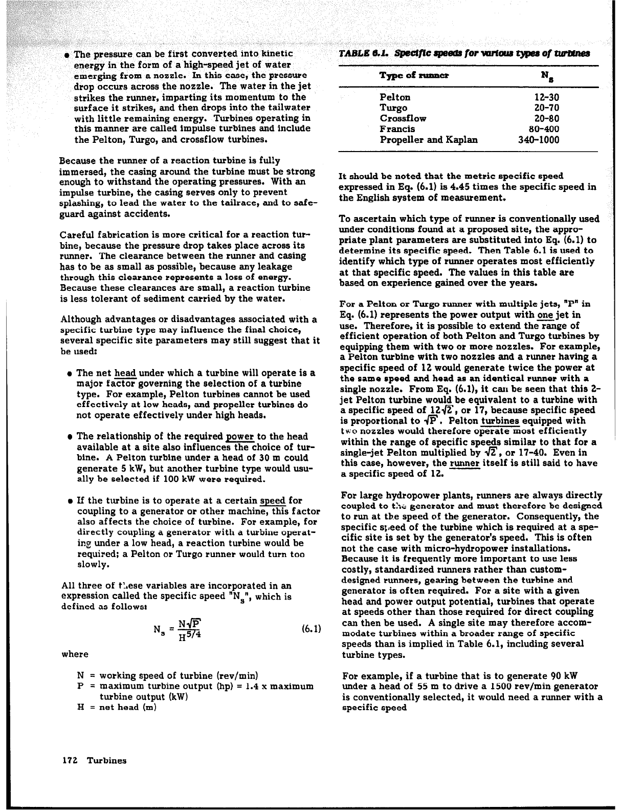
A Pelton turbine has one or more free jets discharging
from nozzles and striking a series of buckets mounted
on the periphery of a disk (Fig. 6.2). Although this tur-
bine is usually not used under a head of less than about
150 m at large hydropower installations, it has been
used down to heads of several meters at micro-hydro-
power installations. The principal reason for not using
this type of turbine at lower heads is that its operating
speed becomes low and the runner becomes unwieldy for
the quantity of power generated. If runner size or speed
poses no obstacle, then a Pelton turbine can be used
under fairly low heads.
Pelton
Fig. 6.2. A Pelton
turbine incorporating
both a needle
valve
to
regulate
one jet
and a fixed Jecond jet.
The
butterfly wlues are used only to twn the flow on or off.
The head under which a Pelton turbine operates has the
following implications for the turbine’s design. At high
heads, enough water emerges from a single jet to gener-
ate the desired power, and the runner revolves at a
speed high enough for direct coupling to a generator or
other end-use equipment.
Assume that identical power is to be generated by the
same runner but that a lower head is available. On the
one hand, a decrease in head leads to a decrease in the
jet velocity and therefore a decrease in runner speed.
On the other hand, because reduced head implies less
water through the nozzle as well as less power associ-
ated with that water, a nozzle with a larger area is
required to pass the increased flow necessary to gener-
ate the same power. However, increasing the jet dia-
meter is feasible only up to a point. There is a maxi-
mum jet diameter, which is set by the size of a bucket
on
the runner being used. Empirical data show that the
maximum jet diameter is about one-third the width of
the bucket.
If the Pelton turbine is used under a still lower head and
the area of a single nozzle can no longer be increased to
maintain the same power output, the next approach is to
increase the effective nozzle area by increasing the
Turbines 17 3
number of jets. The power output from a turbine is
roughly proportional to the number of jets. Two equally
sized jets will make approximately twice the power
available than that from the turbine using a single jet.
In practice, interference between the water and runner
within the casing reduces this value somewhat. When
two jets are used, they usually strike the
rmmer
at
points a little less than 90’ apart.
As head is decreased further, three
or
more jets can be
used. The runner is then set on a vertical rather than
horizontal shaft. Rather than using more than two jets,
another approach is to use two runners side by side on
the same shaft or to place a runner at each end of the
generator shaft.
Pelton runners for micro-hydropower plants usually have
efficiencies of 70%-85%. They have the advantage of
being able to accommodate a wide range of flows with
nearly constant efficiency. For this to be possible, a
turbine must be equipped either with a needle or spear
valve or with nozzles of different sizes which can be
turned on or off as required.
The runaway speed for a Pelton turbine-the speed of
the runner when, under design conditions, all external
loads are removed--is about 1.8 times its normal operat-
ing speed. Under these conditions, bucket speed nearly
equals jet velocity.
In preparing the powerhouse foundation to accept a Pel-
ton turbine, only a hole in the powerhouse floor is
required. It is usually rectangular and is about the size
of the outlet of the turbine casing through which the
water leaving the turbine drops into the tailrace (see
Fig. 5.167). If a pipe section conveys the water from
under the turbine to the tailrace, it must be large
enough so that the water does not back up and submerge
the runner.
Basic relationships
N = runner speed (rev/min)
H = net head (m)
With an impulse turbine such as the Pelton turbine, the
D = runner pitch circle diameter (m)
pressure at the bottom of the penstock creates a jet of
= diameter of circle centered on runner shaft and
water with a velocity
tangent to centerline of jet
where
These equations indicate that, for a given Pelton runner,
its speed depends on the net head acting on the turbine
and is not directly affected by nozzle area or number of
nozzles. Changing nozzle area affects the speed only
insofar as a change in flow affects penstock losses.
Increasing nozzle area, for example, increases the flow
in the penstock, which increases friction loss in the pen-
stock, slightly decreases net head, and slightly
decreases optimum runner speed. From Eq. (6.5) it is
clear that, at a given site,
runner
speed can be changed
significantly only by changing runner diameter.
v.
J
= jet velocity (m/s)
H = net head (m)
g = gravitational constant (9.8 m/s’)
From Eq. (6.2) and the fact that the flow through the
turbine equals the product of jet area and velocity, it is
possible to determine the jet diameter required as a
function of “H”, which depends on site conditions, and
“Q”,
which is determined from the power equation
Eq. (5.11) :
d=--& +--
r
(6.3)
where
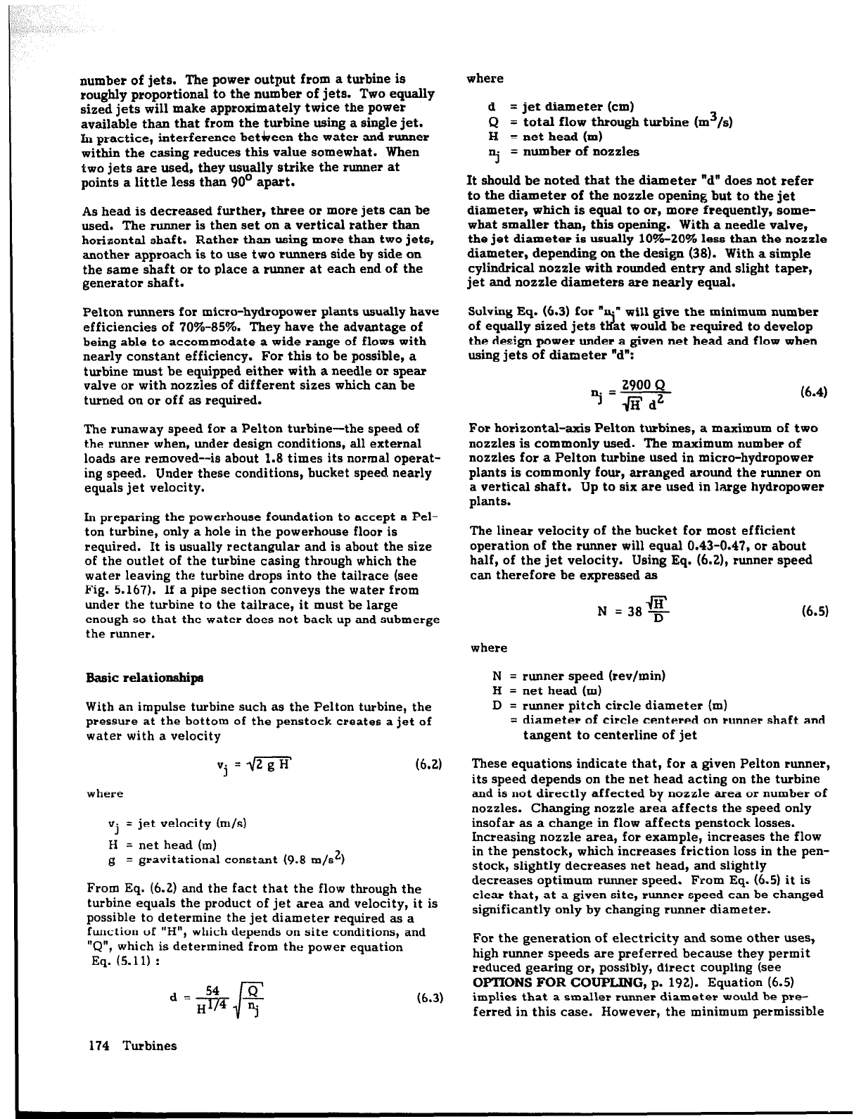
d = jet diameter (cm)
Q = total flow through turbine (xn3/s)
H = net head (m)
“j=
number of nozzles
It should be noted that the diameter “d” does not refer
to the diameter of the nozzle opening but to the jet
diameter, which is equal to or,
more
frequently, some-
what smaller than, this opening. With a needle valve,
the jet diameter is usually lo%-20% less than the nozzle
diameter, depending on the design (38). With a simple
cylindrical nozzle with rounded entry and slight taper,
jet and nozzle diameters are nearly equal.
Solving Eq. (4.3) for ”
.” will give the minimum number
2
of equally sized jets t at would be required to develop
the design power under a given net head and flow when
using jets of diameter ‘d”:
(6.4)
For horizontal-axis Pelton turbines, a maximum of two
nozzles is commonly used. The maximum number of
nozzles for a Pelton turbine used in micro-hydropower
plants is commonly four, arranged around the
runner
on
a vertical shaft. Up to six are used in large hydropower
plants.
The linear velocity
of
the bucket for most efficient
operation of the runner will equal 0.43-0.47, or about
half, of the jet velocity. Using Eq. (6.2), runner speed
can therefore be expressed as
N =38%
(4.5)
where
For the generation of electricity and some other uses,
high runner speeds are preferred because they permit
reduced gearing or, possibly, direct coupling (see
OPTIONS FOR COUPLING, p. 192). Equation (6.5)
implies that a smaller runner diameter would be pre-
ferred in this case. However, the minimum permissible
174 Turbines
bucket size and the minimum number of buckets for
efficient operation set a limit for the minimum size of a
runner:
l
The buckets must be large enough to accommodate
the jet(s).
l
The runner must be large enough to accommodate
the required number of buckets to ensure efficient
operation.
To establish minimum bucket size, years of accumulated
experience indicate that bucket width is rarely less than
three times the jet diameter. This is necessary to
ensure that the water entering the bucket does not
interfere with the water leaving it.
The number of buckets “nb” to ensure efficient opera-
tion can be estimated by the following equation:
nb =9+15
(6.6)
This equation is expressed in terms of a parameter
called the jet or diameter ratio “m”. This is defined as
D
m= -
d
(6.7)
where the jet diameter “d” and the runner diameter “D”
are both expressed in the same units. If too few buckets
are used, a portion of the jet passes through the runner
without striking the buckets. Using too many buckets
leads to their interference with the water leaving the
runner.
To ensure that a runner is large enough to accommo-
date the optimum number of buckets, the diameter ratio
can be used. The minimum value of this ratio has been
found from experience to be about 6. This implies that
the runner diameter cannot be smaller than six times
the jet diameter. The minimum value of the diameter
ratio is the lowest value for which the water in the jet
is still used effectively. Conventionally, this ratio is
usually in the range of 10-20.
Since minimum runner size depends on jet diameter,
the only way of further increasing runner speed is by
decreasing jet diameter. This can be achieved by
increasing the number of jets, as is shown by Eq. (6.3).
Fabrication
Although Pelton runners have been fabricated of sheet
metal and pipe sections (Fig. 6.3), this requires consid-
erable effort.
More frequently, a Pelton runner is
cast-either the buckets are cast individually and bolted
or welded to a central disk, or the runner is cast inte-
grally (Fig. 6.4). Consequently, Pelton turbines gener-
ally require casting facilities, and this may limit their
appeal among those interested in constructing a Pelton
runner for a single site.
A wide variety of bucket shapes has been used. Each
manufacturer of Pelton turbines
has
its own designs,
but
these are proprietary and often difficult to obtain. In
Hydraulic Machines (69), La1 summarizes empirical rela-
tions for basic bucket dimensions and presents typical
plan and section views. In A Pelton Micro-Hydro Proto-
type Design (63), Inversin provides various profiles for a
bucket shape that was synthesized from several sources
(the efficiency of that runner is approximately 75%).
He describes the design of a two-jet Pelton turbo-
generating unit with a 200 mm-diameter runner and
nozzles made from orifice plates and provides a sum-
mary of test results for several different design config-
urations. Another approach has been to use a bucket
from a commercial turbine to prepare a pattern.
Sometimes profiles are selected simply on the basis of
ease of construction. As described in “A Working Pelton
Wheel,” Meinikheim circumvented the need for casting
facilities and machined his buckets out of steel (80).
The bucket profile was determined by the shape of the
Turbines 175
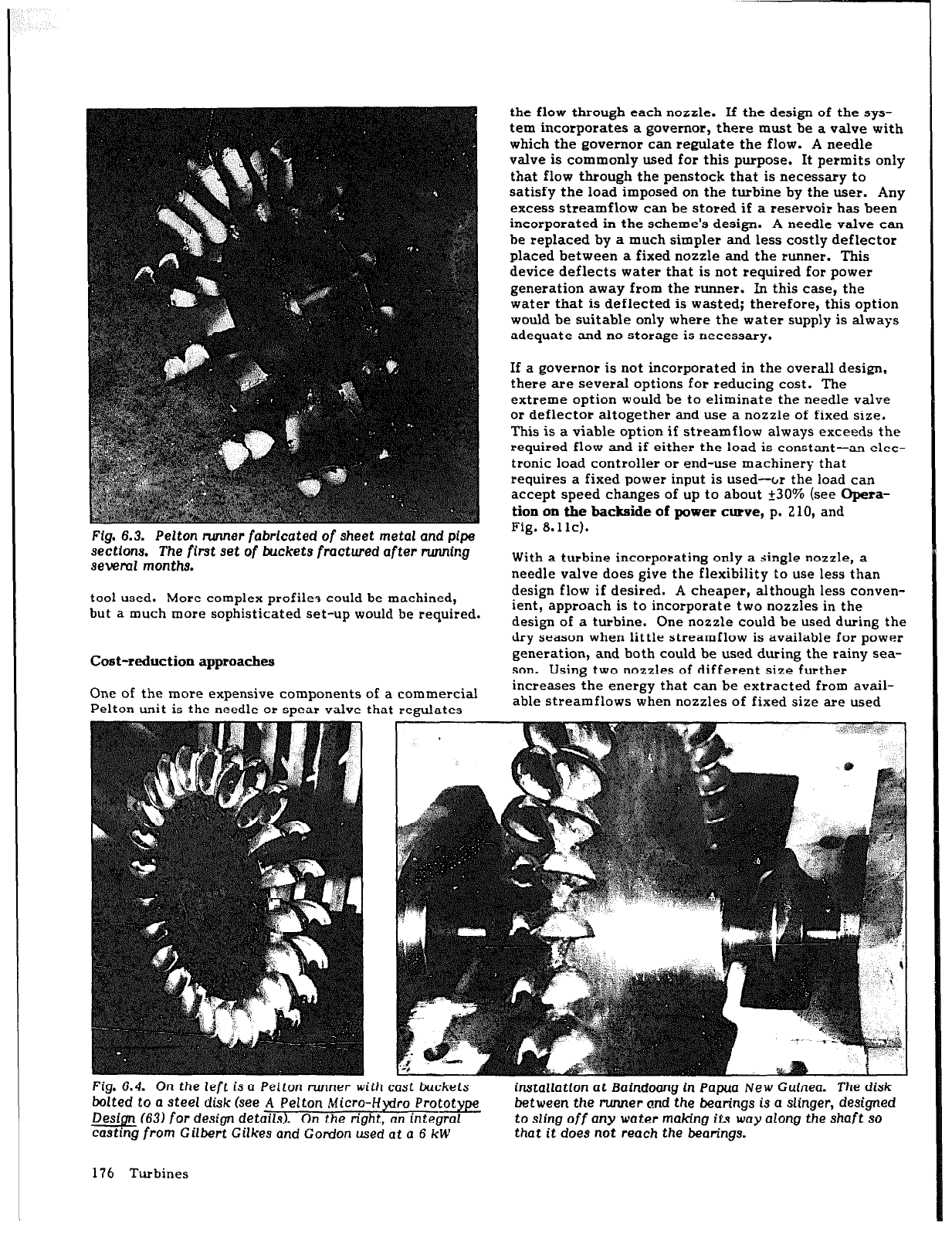
Flg. 6.3. Pelton runner fabrfcated of sheet metal and pipe
sections.
The first set of buckets fractured
after rwming
seveml months.
tool used. More complex profile-, could be machined,
but a much more sophisticated set-up would be required.
Cost-reduction approaches
One of the more expensive components of a commercial
Pelton unit is the needle or spear valve that regulates
the flow through each nozzle. If the design of the sys-
tem incorporates a governor, there must be a valve with
which the governor can regulate the flow. A needle
valve is commonly used for this purpose. It permits only
that flow through the penstock that is necessary to
satisfy the load imposed on the turbine by the user. Any
excess streamflow can be stored if a reservoir has been
incorporated in the scheme’s design. A needle valve can
be replaced by a much simpler and less costly deflector
placed between a fixed nozzle and the runner. This
device deflects water that is not required for power
generation away from the runner. In this case, the
water that is deflected is wasted; therefore, this option
would be suitable only where the water supply is always
adequate and no storage is necessary.
If a governor is not incorporated in the overall design,
there are several options for reducing cost. The
extreme option would be to eliminate the needle valve
or deflector altogether and use a nozzle of fixed size.
This is a viable option if streamflow always exceeds the
required flow and if either the load is constant-an elec-
tronic load controller or end-use machinery that
requires a fixed power input is used-or the load can
accept speed changes of up to about 230% (see Qpera-
tion on the backside of power curve, p. 210, and
Fig. 8.1 lc).
With a turbine incorporating only a single nozzle, a
needle valve does give the flexibility to use less than
design flow if desired. A cheaper, although less conven-
ient, approach is to incorporate two nozzles in the
design of a turbine. One nozzle could be used during the
dry season when little streamflow is available for power
generation, and both could be used during the rainy sea-
son. Using two nozzles of different size further
increases the energy that can be extracted from avail-
able streamflows when nozzles of fixed size are used
Fig.
6.4. On the
left
is a Peiton runner
with cast buckets
bolted to a
steel
disk (see A Pelton Micro-lfydro Prototype
On the right, an integral Desip (63) for
design
details).
castmg from Gilbert Gilkes and Gordon used at
a 6
kW
installation
at Baindoang in Papua New Guinea. The disk
between
the runner and the
bearings
is a slinger, designed
to
sling
off any water making its way along the shaft so
that it does not
reach
the bearings.
176 Turbines
(see the end of Alternative turbine configurations,
p. 42). If a single-jet turbine is used, it could be
designed with interchangeable nozzles of different
sizes. This approach requires that the plant be shut
down to permit changing the nozzles. The cost-reduc-
tion advantage gained may be offset by the increased
bother associated with performing this task.
The profile of conventional nozzles is a continuous
curve that requires careful machining. A more basic
nozzle is simply a metal cylinder with a slightly tapered
bore and rounded leading edge so that the flow does not
separate on entering.
A very rudimentary but often adequate nozzle is simply
a sharp-edged orifice-a hole drilled through a sheet of
metal. The flow separates from the inside edge of the
plate and emerges as a well-defined jet. Pressure losses
through an orifice plate are insignificant. After leaving
this type of nozzle, the jet may diverge slightly faster
than one emerging from a well-designed nozzle, but this
has no major effect if the nozzle is close to the runner.
This nozzle can be made at almost no cost. A series of
plates with orifices of different diameters can be used
to vary the flow through a turbine. In sizing an orifice,
it is necessary to keep in mind that the flow contracts
on flowing through the orifice and that the jet diameter
is about 0.8 times the diameter of the orifice. The jet
can be expected to increase somewhat as the inside
edge of the orifice wears with use. This type of nozzle
has already been used in several cases (59,63).
Turgo turbines
Gilbert Gilkes and Gordon Limited of the United King-
dom developed and manufactures the Turgo turbine
which can operate under a head in the range of 30-
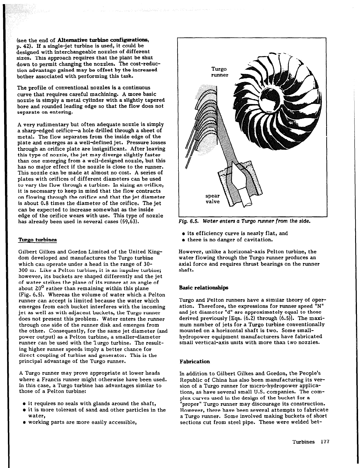
300 m. Like a Pelton turbine, it is an impulse turbine;
however, its buckets are shaped differently and the jet
of water strikes the plane of its runner at an angle of
about 20’ rather than remaining within this plane
(Fig. 6.5). Whereas the volume of water which a Pelton
runner can accept is limited because the water which
emerges from each bucket interferes with the incoming
jet as well as with adjacent buckets, the Turgo runner
does not present this problem. Water enters the runner
through one side of the runner disk and emerges from
the other. Consequently, for the same jet diameter (and
power output) as a Pelton turbine, a smaller-diameter
runner can be used with the Turgo turbine. The result-
ing higher runner speeds imply a better chance for
direct coupling of turbine and generator. This is the
principal advantage of the Turgo runner.
A Turgo runner may prove appropriate at lower heads
where a Francis runner might otherwise have been used.
In this case, a Turgo turbine has advantages similar to
those of a Pelton turbine:
o it requires no seals with glands around the shaft,
e it is more tolerant of sand and other particles in the
water,
o working parts are more easily accessible,
valve
m
‘fg. 6.5. Woter enters a Tvgo nmner from the side.
o its efficiency curve is nearly flat, and
o there is no danger of cavitation.
However, unlike a horizonal-axis Pelton turbine, the
water flowing through the Turgo runner produces an
axial force and requires thrust bearings on the runner
shaft.
Basic relationships
Turgo and Pelton runners have a similar theory of oper-
ation. Therefore, the expressions for runner speed “N”
and jet diameter “d” are approximately equal to those
derived previously [Eqs. (6.2) through (6.5)). The maxi-
mum number of jets for a Turgo turbine conventionally
mounted on a horizontal shaft is two. Some small-
hydropower equipment manufacturers have fabricated
small vertical-axis units with more than two nozzles.
Fabrication
In addition to Gilbert Gilkes and Gordon, the People’s
Republic of China has also been manufacturing its ver-
sion of a Turgo runner for micro-hydropower applica-
tions, as have several small U.S. companies. The com-
plex curves used in the design of the bucket for a
“proper” Turgo runner may discourage its construction.
However, there have been several attempts to fabricate
a Turgo runner. Some involved making buckets of short
sections cut from steel pipe. These were welded bet-
Turbines 1’77
ween two concentric steel bands. The iMer band was
welded around the circumference of a steel disk that
served as the hub.
The Nepalese “ghatta” (see Fig. 10.7) is a runner whose
operation roughly approximates that of a Turgo runner.
Thousands of ghattas have been in operation in Nepal
and elsewhere for centuries, providing mechanical
power for milling (see PRX’VATESECTQR APPROACH
To IMPLEMENTING MICRO-HYDROPOWER SCHEMES
M NEPAL, p. 226). They are built primarily of wood.
Activating Traditional Indigenous Techniques: Devel-
opment and Improvement of the Nepalese Watermill
‘Ghatta’ (98) describes traditional designs and changes
proposed to improve their efficiency,
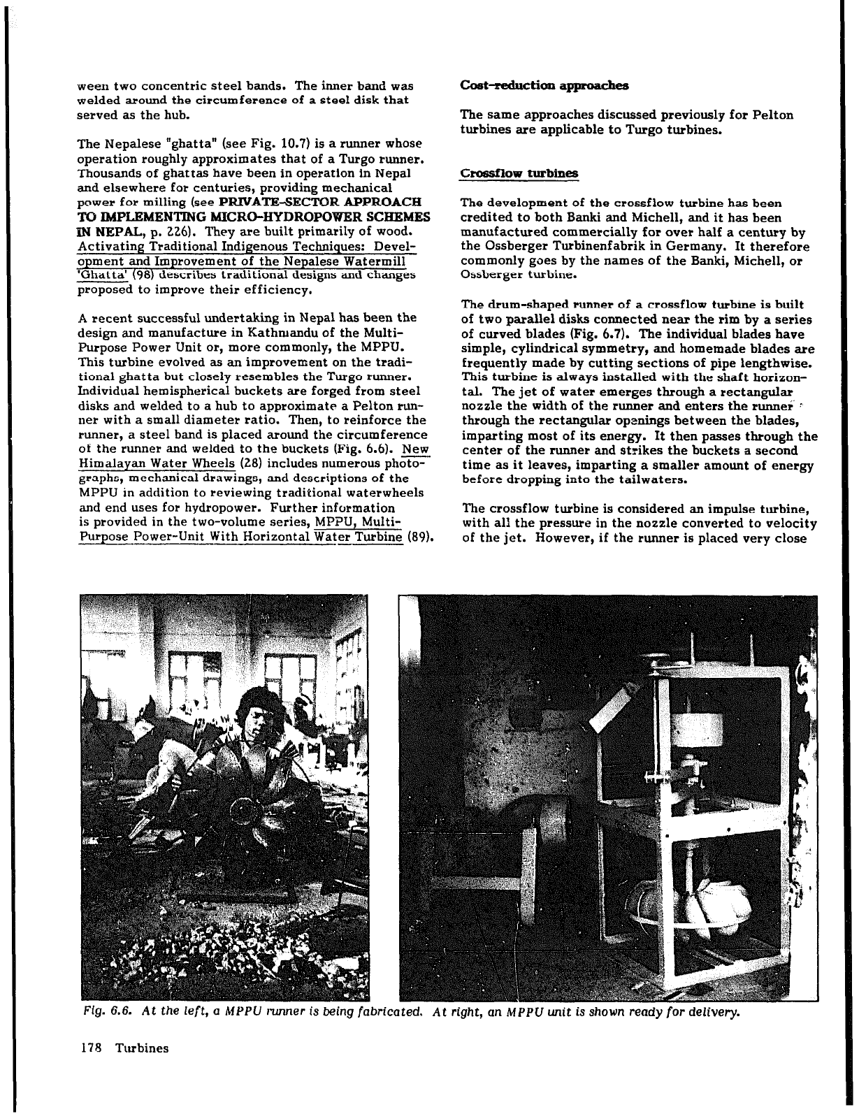
A recent successful undertaking in Nepal has been the
design and manufacture in Kathmandu of the Multi-
Purpose Power Unit or, more commonly, the MPPU.
This turbine evolved as an improvement on the tradi-
tional ghatta but closely resembles the Turgo runner.
Individual hemispherical buckets are forged from steel
disks and welded to a hub to approximate a Pelton run-
ner with a small diameter ratio. Then, to reinforce the
runner, a steel band is placed around the circumference
of the runner and welded to the buckets (Fie.
6.6). New
Himalayan Water Wheels (28) includes num&ous photo-
graphs, mechanical drawings, and descriptions of the
MPPU in addition to reviewing traditional waterwheels
and end uses for hydropower. -Further information
is nrovided in the two-volume series. MPPU. Multi-
P&pose Power-Unit With Horizontal Water Turbine (89).
Coat~on appmachs
The same approaches discussed previously for Pelton
turbines are applicable to Turgo turbines.
Crossflow turbines
The development of the crossflow turbine has been
credited to both Banki and Michell, and it has been
manufactured commercially for over half a century by
the Ossberger Turbinenfabrik in Germany. It therefore
commonly goes by the names of the Banki, Michell,
or
Ossberger turbine.
The drum-shaped runner of a crossflow turbine is built
of two parallel disks connected near the rim by a series
of curved blades (Fig. 6.7). The individual blades have
simple, cylindrical symmetry, and homemade blades are
frequently made by cutting sections of pipe lengthwise.
This turbine is always installed with the shaft horizon-
tal. The jet of water emerges through a rectangular
nozzle the width of the
rmner
and enters the runner c
through the rectangular openings between the blades,
imparting most of its
energy.
It then passes through the
center of the runner and strikes the buckets a second
time as it leaves, imparting a smaller amount of energy
before dropping into the tailwaters.
The crossflow turbine is considered an impulse turbine,
with all the pressure in the nozzle converted to velocity
of the jet. However, if the
runner
is placed
very
close
FL&!. 6.6.
At
the
left, a
MPPU runner is being fabricated,
At right, en MPpU unit is
shown ready for delivery.
178 Turbines
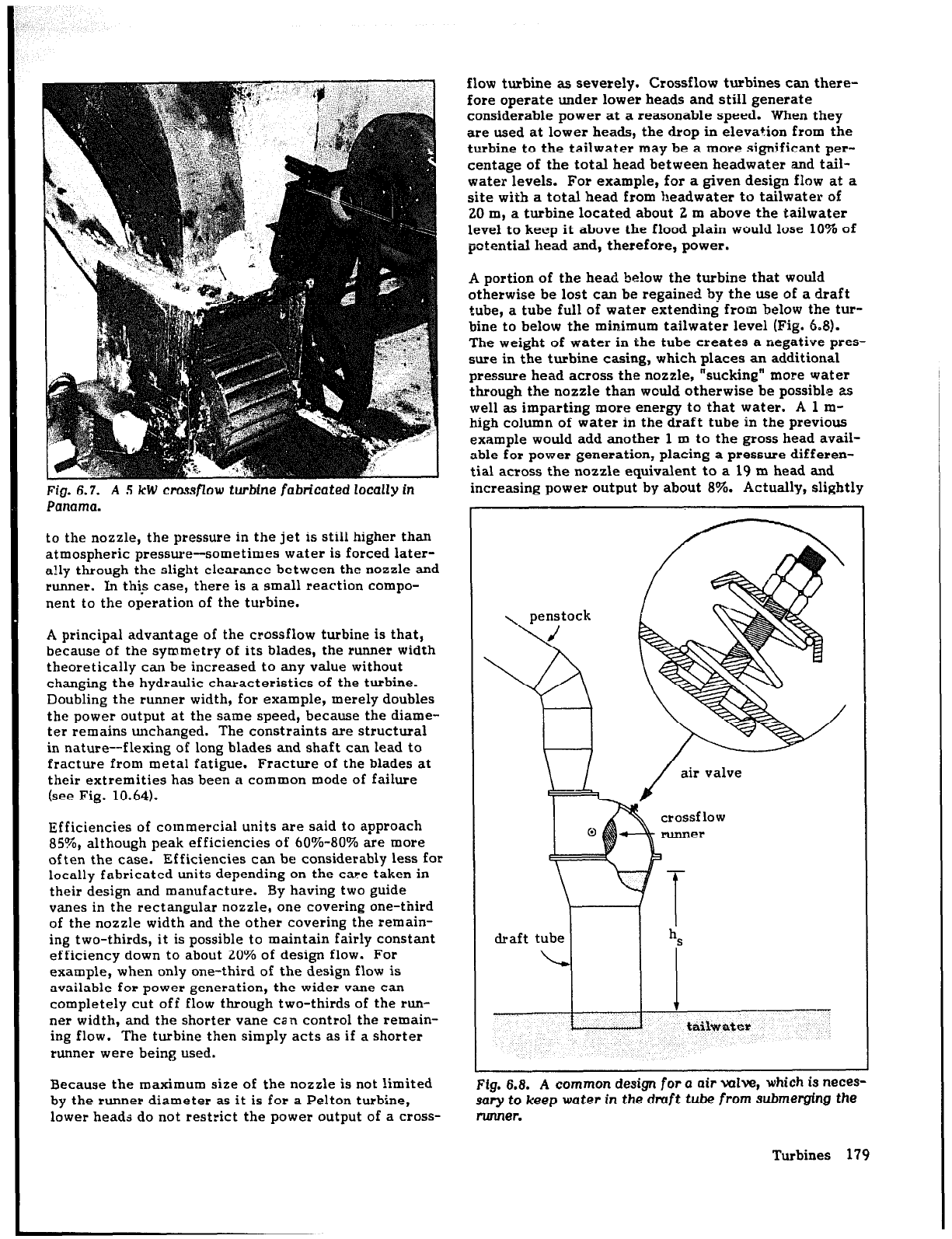
Fig. 6.7. A 5 kW crossflow turbine fabricated locally in
Panama.
to the nozzle, the pressure in the jet is still higher than
atmospheric pressure-sometimes water is forced later-
ally through the slight clearance between the nozzle and
runner. In this case, there is a small reaction compo-
nent to the operation of the turbine.
A principal advantage of the crossflow turbine is that,
because of the symmetry of its blades, the runner width
theoretically can be increased to any value without
changing the hydraulic characteristics of the turbine.
Doubling the runner width, for example, merely doubles
the power output at the same speed, because the diame-
ter remains unchanged. The constraints are structural
in nature--flexing of long blades and shaft can lead to
fracture from metal fatigue. Fracture of the blades at
their extremities has been a common mode of failure
(see Fig. 10.64).
Efficiencies of commercial units are said to approach
85%, although peak efficiencies of 60%-80% are more
often the case. Efficiencies can be considerably less for
locally fabricated units depending on the care taken in
their design and manufacture. By having two guide
vanes in the rectangular nozzle, one covering one-third
of the nozzle width and the other covering the remain-
ing two-thirds, it is possible to maintain fairly constant
efficiency down to about 20% of design flow. For
example, when only one-third of the design flow is
available for power generation, the wider vane can
completely cut off flow through two-thirds of the run-
ner width, and the shorter vane can control the remain-
ing flow. The turbine then simply acts as if a shorter
runner were being used.
Because the maximum size of the nozzle is not limited
by the runner diameter as it is for a Pelton turbine,
lower heads do not restrict the power output of a cross-
flow turbine as severely. Crossflow turbines can there-
fore operate under lower heads and still generate
considerable power at a reasonable speed. When they
are used at lower heads, the drop in elevation from the
turbine to the tailwater may be a more significant per-
centage of the total head between headwater and tail-
water levels. For example, for a given design flow at a
site with a total head from ?leadwater to tailwater of
20 m, a turbine located about 2 m above the tailwater
level to keep it above the flood plain would lose 10% of
potential head and, therefore, power.
A portion of the head below the turbine that would
otherwise be lost can be regained by the use of a draft
tube, a tube full of water extending from below the tur-
bine to below the minimum tailwater level (Fig. 6.8).
The weight of water in the tube creates a negative pres-
sure in the turbine casing, which places an additional
pressure head across the nozzle, “sucking” more water
through the nozzle than would otherwise be possible as
well as imparting more energy to that water. A 1 m-
high column of water in the draft tube in the previous
example would add another 1 m to the gross head avail-
able for power generation, placing a pressure differen-
tial across the nozzle equivalent to a 19 m head and
increasing power output by about 8%. Actually, slightly
draft tube
I
h
S
i.
tiiikwater
-
lg. 6.8.
A
common
design for a air valve, which is neces-
nry to keep water
in
the draft tube from submerging the
unner.
Turbines 179