Inversin R. Allen Micro-hydropower Sourcebook
Подождите немного. Документ загружается.

less head than “hs” can be recovered, because the flow
in the draft tube is aerated, reducing somewhat the
weight of the column of water inside. There are also
losses caused by friction and turbulence within the draft
tube. It is not possible to recover the entire head repre-
sented by the distance from nozzle to tailwater level;
that would imply a submerged runner. Unlike reaction
turbines, a crossflow runner has to operate in air.
Pelton and Turgo runners can also operate with draft
tubes. However, these turbines are generally used at
high-head sites, and the distance between the turbine
and tailwater is therefore insignificant compared to the
head above the turbine.
One difficulty in using a draft tube with a runner that
operates in air is that air within the casing will gradu-
ally be entrained or dissolved in the water. The water
level in the draft tube will then rise, gradually submerg-
ing the runner and significantly reducing its efficiency.
Consequently, an air valve is incorporated in the turbine
casing (Fig.
6.8).
It is adjusted so that when the water
in the draft tube is higher than the permissible suction
head “hS” (set by the turbine’s need to operate in air),
the negative pressure in the casing pulls in additional
outside air, permitting the water column to drop
slightly.
Although a draft tube permits additional power to be
generated at a specific site, stuffing boxes must be
located where the shaft enters the casing and the casing
must be fairly airtight. Significant leaks in the casing
or draft tube will make the draft tube totally ineffec-
tive. Therefore, extra care and expense in the design
and fabrication of the turbine is required to gain extra
head, and therefore power, through the use
of
a draft
tube.
For micro-hydropower turbines, a draft tube used to
recover a major portion of the potential energy or head
between the turbine and tailwater is often cvlindrical in
shape-simply a length of pipe with its outlet end always
submerged below tailwater level. However, the water
descending a draft tube still has velocity and therefore
kinetic epergy, which represents a loss in head equiva-
lent to v‘/2g, where “v” is the water velocity in the
draft tube. If this is significant, as is more often the
case with reaction turbines, a portion of this head can
be recovered by gradually increasing the cross-sectional
area of the draft tube. This causes the velocity in the
draft tube to decrease as it descends; the decrease in
kinetic energy is converted to an increase in potential
energy manifested in the increase in negative pressure
or suction in the turbine casing.
A draft tube used with a small turbine to recover some
of this kinetic enerm is generally conical in shape.
Although a quickly diverging draft tube would seem
preferable to -reduce the velocity as much as possible
with the shortest possible draft tube, the maximum cone
angle is about 8’.
With greater angles, the flow
detaches from the walls, creating turbulence and an
accompanying loss of energy and head.
Basic relat.iolIships
“The Banki Water Turbine” (85) probably contains one of
the first descriptions in English of the design and opera-
tion of a crossflow turbine, along with test results of a
prototype. The initial portion of this publication is a
loose translation of the original paper by Donati Banki,
“Neue Wasserturbiie.”
For preliminq design purposes, equations and other
common relationships that can be useful in approximat-
ing overall runner dimensions and speed are as follows:
(6.8)
where
A = cross-sectional area of jet (m2)
s (jet thickness, m) x (runner length, m)
Q = flow (m3/s)
H = net head (m)
Making a first guess for a runner length and using the
definition for “A” above will permit the jet thickness to
be determined. The cross-sectional width
of
the
rec-
tangular nozzle of a crossflow turbine is approximately
equal to the jet thickness. The runner diameter is usu-
ally about 10 times the jet thickness. If the runner
dimensions seem unreasonable, another estimate for
runner length should be tried. Then, when the runner
diameter is found, its speed can be found as follows:
where
N = runner speed (rev/min)
D = runner diameter (m)
Fabrication
Because of the simplicity of its design and the fact that
the construction
of
the runner requires only cutting,
welding, and grinding (or machining, if available), the
crossflow turbine is the most popular turbine for local
fabrication. In addition, numerous publications describ-
ing the construction of crossflow turbines are available.
The first popular publication describing the desi@ and
construction of a crossflow turbine was VITA’s Low Cost
Development of Small Water Power Sites (56). In addi-
tion to providing summary information on developing a
hydropower site, it presents some details for construct-
ing a turbine. The vanes for this design are cut from
sections of steel pipe and are inserted in grooves cut
into the two circular end-plates. This design is also
summarized in the Energy Primer (8). Because of the
effort required to cut these grooves, many have omitted
this step and simply arc-welded the vanes to the end-
plates. Langhorne has documented his experience in
180 Turbines
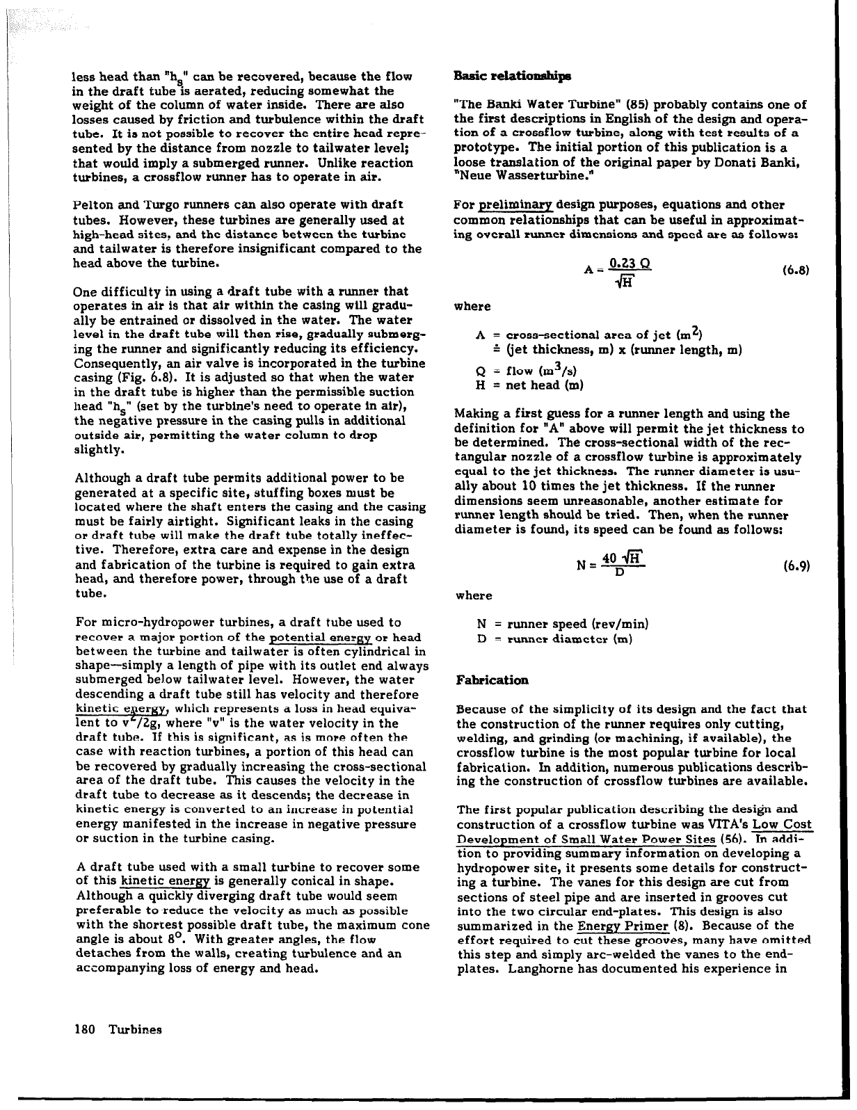
constructing a crossflow turbine after the VITA design
and implementing a hydropower scheme (Fig. 6.9) in his
article, “Hand-Made Hydro Power” (70).
ln addition to reviewing one of several Nepalese efforts
to design turbines and implement small-hydropower
schemes, Small Water Turbines (97) presents detailed
machine drawings of all the components of the stan-
dardized designs manufactured by Butwal Engineering
Works. It also describes and illustrates jigs used to
facilitate fabrication. This publication is presently
being updated.
Fig.
6.9. This 6
kW scheme, using
a homemade
crossflow
turbine,
reduces demand placed by a private residence on
utility
power.
A complete set of detailed designs for a turbine with a
runner diameter of 200 mm (Fig. 6.10), manufactured by
the Nepalese company Balaju Yantra Shala, is found in
Crossflow Turbine, Type: BYS/T3 (4). Arter also con-
tributed to this design; details of his work and extensive
test results can be found in two theses in German,
Durchstrijmturbine (27) and Experimentelle Unter-
suchung einer DurchstrGmturbine des Typs Banki (34).
In addition to the previous publications, there has been
other university-based research on the crossflow tur-
bine. Design of Small Water Turbines for Farms and
Small Communities (43), prepared at the Massachusetts
Institute of Technology, quantitatively reviews the
design of a crossflow turbine. Although the objective of
this study was to develop a design that could be fabri-
cated in a simple workshop in a developing country, with
facilities to weld, drill, and cut steel parts, no prototype
was built or tested. Consequently, although this publi-
cation may give some insight into the design of a cross-
flow turbine, the preliminary design which it presents
lacks design improvements that would have been appar-
ent if prototypes had been built and field-tested.
Hothersall’s thesis, Micro-hydro Development for
P.N.G. (60), describes another effort to design and
fabricate a crossflow turbine. In “A Review of the
Cross-Flow Turbine,” Hothersall provides a technical
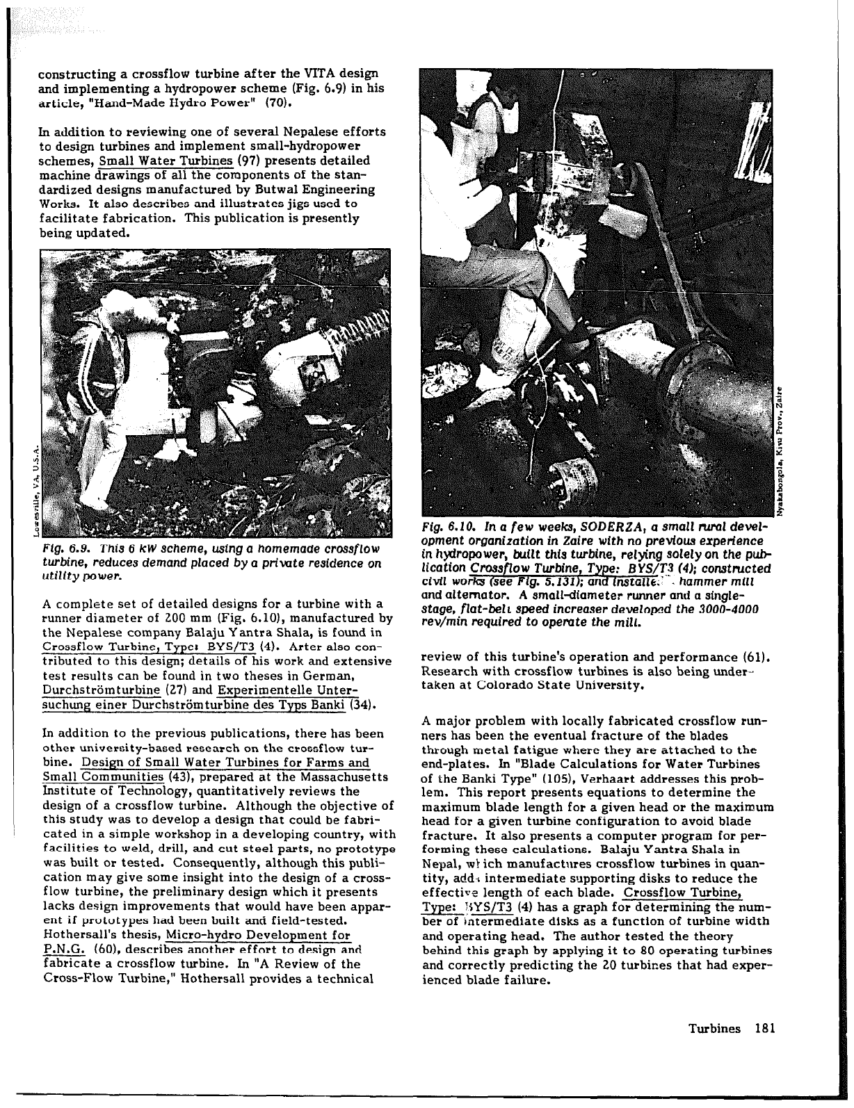
Fig. 6.10. In
a few weeks, SODERZA, a small NW deW-
opment
organization in Zaire with no previous
experience
in hydropower, buflt this
turbine, retying solely on
the pub-
lication Crossflow Turbine, Type: EYS/TI (4); consthtcted
civil
works (see Flg. 5.131); and in.stallc;“W. hammer mill
and alternator. A small-diameter runner and a stngle-
stage,
flat-bell speed increaser develowd the 3000-4000
rev/min
required to
operate the mill.
review of this turbine’s operation and performance (61).
Research with crossflow turbines is also being under-
taken at Colorado State University.
A major problem with locally fabricated crossflow run-
ners has been the eventual fracture of the blades
through metal fatigue where they are attached to the
end-plates. In “Blade Calculations for Water Turbines
of the Banki Type” (105), Verhaart addresses this prob-
lem. This report presents equations to determine the
maximum blade length for a given head or the maximum
head for a given turbine configuration to avoid blade
fracture. It also presents a computer program for per-
forming these calculations. Balaju Yantra Shala in
Nepal, wl ich manufactures crossflow turbines in quan-
tity, add* intermediate supporting disks to reduce the
effective length of each blade. Crossflow Turbine,
Type: T$YS/T3 (4) has a graph for determining the num-
ber of intermediate disks as a function of turbine width
and operating head. The author tested the theory
behind this graph by applying it to 80 operating turbines
and correctly predicting the 20 turbines that had exper-
ienced blade failure.
Turbines 18 1
Cost-reduction approaches
Among the lowest-cost crossflow turbines in use
today
are those in northern Pakistan (see VILLAGER-IMPLE-
MENTED WCRO-HYDROPOWER SCHEMES ZN PAKIS-
TAN, p. 248). In a number of these installations, the
cost of the casing has been eliminated; pillow blocks
mounted on timber or concrete support the turbine
bearings (see Fig. 10.55). The runner is simply covered
with wooden slats or a sheet of galvanized roofing to
prevent the spray from reaching the bearings, belts, and
generator. A draft tube cannot be used at such an
installation, but additional head is often gained by
locating the runner about 2 m below the floor of the
powerhouse, with belts to transmit the power upward
(see Fig. 10.43). Placing a turbine below floor level also
keeps leaking water off the powerhouse floor.
Designs for crossflow turbines usually include a nozzle
made of sheet metal bent to a prescribed shape and
positioned to minimize clearance between the nozzle
and runner. hi addition, a short section of pipe is com-
monly used to make a smooth transition from a cylindri-
cal penstock to a rectangular nozzle. This is another
piece which has to be fabricated and which slightly
increases cost. Nozzles of simpler designs include one
made of flat metal sheets (see Fig. 10.55), one made by
forming a rectangular opening in one end of an oil drum
(see Fig. 10.561, and one made by using rectangular steel
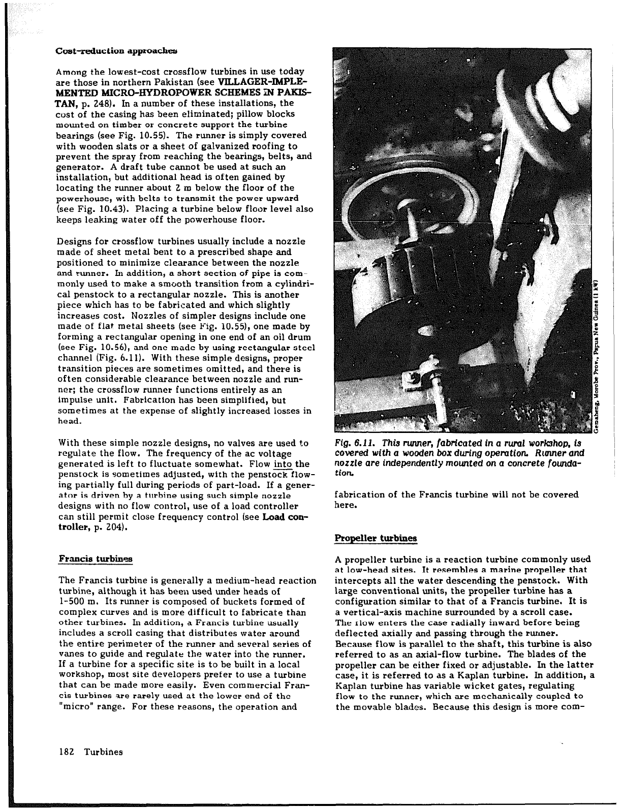
channel (Fig. 6.11). With these simple designs, proper
transition pieces are sometimes omitted, and there is
often considerable clearance between nozzle and run-
ner: the crossflow runner functions entirely as an
impulse unit.
Fabrication has been simplified, but
sometimes at the expense of slightly increased losses in
head.
With these simple nozzle designs, no valves are used to
regulate the flow. The frequency of the ac voltage
generated is left to fluctuate somewhat. Flow into the
penstock is sometimes adjusted, with the penstock flow-
ing partially full during periods of part-load. If a gener-
ator is driven by a turbine using such simple nozzle
designs with no flow control, use of a load controller
can still permit close frequency control (see Load con-
troller, p. 204).
Francis turbines
The Francis turbine is generally a medium-head reaction
turbine, although it has been used under heads of
l-500 m. Its runner is composed of buckets formed of
complex curves and is more difficult to fabricate than
other turbines. In addition, a Francis turbine *usually
includes a scroll casing that distributes water around
the entire perimeter of the runner and several series of
vanes to guide and regulate the water into the runner,
If a turbine for a specific site is to be built in a local
workshop, most site developers prefer to use a turbine
that can be made more easily. Even commercial Fran-
cis turbines are rarely used at the lower end of the
“micro” range. For these reasons, the operation and
182 Turbines
Ffg. 6.11. This runner, fabricated In a rwul workshop, is
covered
with
a
wooden
box
during
opemtion
Runner and
nozzle are independently
mounted
on
a concrete founda-
tion
fabrication of the Francis turbine will not be covered
here.
Propeller turbines
A propeller turbine is a reaction turbine commonly used
at low-head sites. It resembles a marine propeller that
intercepts all the water descending the penstock. With
large conventional units, the propeller turbine has a
configuration similar to that of a Francis turbine. It is
a vertical-axis machine surrounded by a scroll case.
The rlow enters the case radially inward before being
deflected axially and passing through the runner.
Because flow is parallel to the shaft, this turbine is also
referred to as an axial-flow turbine. The blades of the
propeller can be either fixed or adjustable. In the latter
case, it is referred to as a Kaplan turbine. In addition, a
Kaplan turbine has variable wicket gates, reflating
flow to the runner, which are mechanically coupled to
the movable blades. Because this design is more com-
plex than others, this configuration is not often used
with micro-hydropower schemes.
There are several other configurations for this type of
turbine, all of which permit the flow to enter or leave
with less significant changes in direction. Micro-hydro-
power turbines are commercially available in all three
basic configurations described below:
l
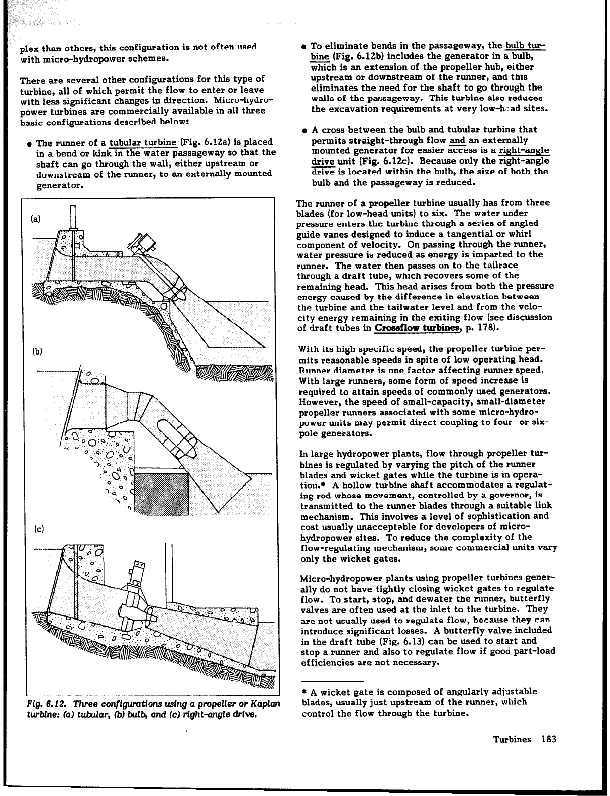
The runner of a tubular turbine (Fig. 6.12a) is placed
in a bend
or
kink in the water passageway so that the
shaft can go through the wall, either upstream
or
downstream of the runner, to an externally mounted
generator.
n
(a)
II
Fig. 6.12. Three configuratIons usfng a propeller or
Kaplan
turbine: (a) tubular, 0
buI4
and (cc) rtght-angle dtive.
l
To eliminate bends in the passageway, the bulb tur-
bine (Fig. 6.12b) includes the generator in a bulb,
which is an extension of the propeller hub, either
upstream or downstream of the
runner,
and this
eliminates the need for the shaft to go through the
walls of the p=Jsageway. This turbine also reduces
the excavation requirements at very low-h.Tad sites.
l
A cross between the bulb and tubular turbine that
permits straight-through flow and an externally
mounted generator for easier access is a right-angle
drive unit (Fig. 6.12~). Because only the right-angle
drive is located within the bulb, the size of both the
bulb and the passageway is reduced.
The runner of a propeller turbine usually has from three
blades (for low-head units) to six. The water under
pressure enters the t-urbine through a series of angled
guide vanes designed to induce a tangential
or
whirl
component of velocity. On passing through the runner,
water pressure is reduced as energy is imparted to the
runner. The water then passes on to the tailrace
through a draft tube, which recovers some of the
remaining head. This head arises from both the pressure
energy caused by the difference in elevation between
the turbine and the tailwater level and from the velo-
city energy remaining in the exiting flow (see discussion
of draft tubes in Croaaflow
turbines,
p. 178).
With its high specific speed, the propeller turbine per-
mits reasonable speeds in spite
of
low operating head.
Runner
diameter is one factor affecting runner speed.
With large runners, some form of speed increase is
required to attain speeds of commonly used generators.
However, the speed of small-capacity, small-diameter
propeller runners associated with some micro-hydro-
power units may permit direct coupling to four- or six-
pole generators.
In large hydropower plants, flow through propeller tur-
bines is regulated by varying the pitch of the runner
blades and wicket gates while the turbine is in opera-
tion.* A hollow turbine shaft accommodates a regulat-
ing rod whose movement, controlled by a governor, is
transmitted to the runner blades through a suitable link
mechanism. This involves a level of sophistication and
cost usually unacceptable for developers of micro-
hydropower sites. To reduce the complexity of the
flow-regulating mechanism, some commercial units vary
only the wicket gates.
Micro-hydropower plants using propeller turbines gener-
ally do not have tightly closing wicket gates to regulate
flow. To start, stop, and dewater the runner, butterfly
valves are often used at the inlet to the turbine. They
are not usually used to regulate flow, because they
can
introduce significant losses. A butterfly valve included
in the draft tube (Fig. 6.13) can be used to start and
stop a runner and also to regulate flow if good part-load
efficiencies are not necessary.
* A wicket gate is composed of angularly adjustable
blades, usually just upstream of the runner, which
control the flow through the turbine.
Turbines 183
keep in mind the rapid closure possible with a butterfly
valve (see &Itterfly p. 159) and its impact on
surge pressures in the penstock (see discussion of surge
pressures in Sl
-
m p. 133).
As with all reaction turbines, propeller runners face a
problem with cavitation. As water passes over the run-
ner, the pressure may decrease to the point that water
vaporizes, forming bubbles. When these bubbles are
carried downstream to area5 of greater pressure, they
collapse violently, producing very large instantaneous
pressures that fatigue and erode any nearby surface.
Cavitation leads to pitting of the runner, which can
eventually eat away entire portions of the blades,
thereby reducing turbine efficiency. It is accompanied
by vibration and a noise similar to that of gravel in a
rotating
vessel.
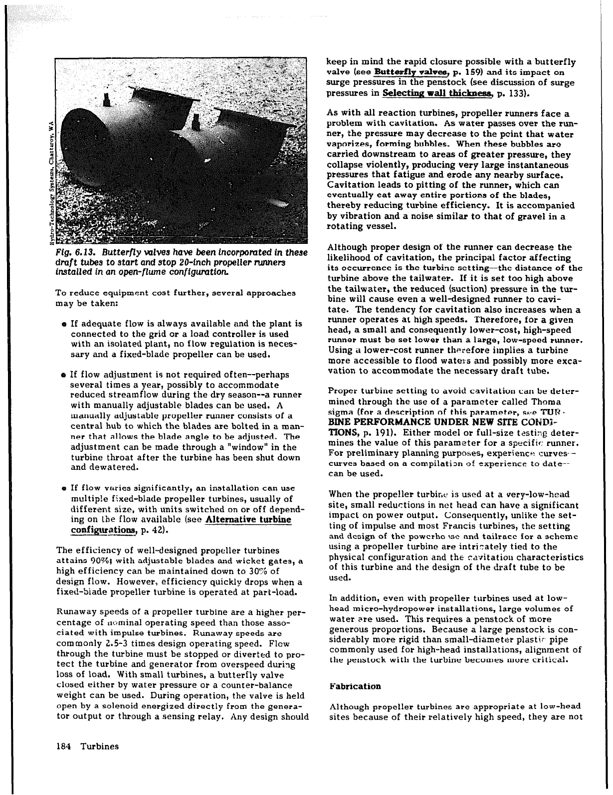
Fig.
6.13. Butterfly
valves have been lncorpomted in
these
draft tubes to start and stop 2O-inch
propeller runners
installed
in an open-flume configuration
To reduce equipment cost further, several approaches
may be taken:
e If adequate flow is always available and the plant is
connected to the grid or a load controller is
used
with an isolated plant, no flow regulation is neces-
sary and a fixed-blade propeller can be used.
o If flow adjustment is not required often--perhaps
several times a year, possibiy to accommodate-
reduced streamflow during the dry season--a
runner
with manually adjustable blades can bc used. A
manually adjustable propeller runner consists of a
central hub to which the blades are bolted in a man-
ner that allows the blade angle to be adjusted. The
adjustment can be made through a “window” in the
turbine throat after the turbine has been shut down
and dewatered.
Although proper design of the runner can decrease the
likelihood of cavitation, the principal factor affecting
its occurrence is the turbine setting-the distance of the
turbine above the tailwater. If it is set too hinh above
the tailwater, the reduced (suction) pressure ii the tur-
bine will cause even a well-designed
runner
to cavi-
tate. The tendency for cavitation also increases when a
runner operates at high speeds. Therefore, for a given
head, a small and consequently lower-cost, high-speed
runner must be set lower than a large, low-speed runner’.
Using io lower-cost runner thtlrefore implies a turbine
more accessible to flood waters and possibly
more
exca-
vation to accommodate the necessary draft tube.
a If flow varies significantly, an installation can use
multip!e fixed-blade propeller turbines, usually of
different size, with units switched on or off depend-
ing on Lhe flow available (see Alternative hub&e
configurcations, p. 42).
The efficiency of well-designed propeller turbines
attains 10%; with adjustable blades and wicket gat.es, a
high efficiency can be maintained down to 30% of
design flow. However, efficiency quickly drops when a
fixed-Siade propeller turbine is operated at part-load.
Runaway speeds of a propeller turbine are a higher per-
centage of nominal operating speed than those asso-
ciated with impulse turbines. Runaway speeds are
commonly 2.5-3 times design operating speed. Flew
through the turbine must be stopped or diverted to pro-
tect the turbine and generator from overspeed during
loss of load. With small turbines, a butterfly valve
closed either by water pressure or a counter-balance
weight can be used. During operation, the valve is held
open by a solenoid energized directly from the genera-
tor output or through a sensing relay. Any design should
Proper turbine setting to avoid cavitation can be deter-
mined through the use of a parameter called Thoma
sigma (for a description of this parameter, s+:e TUR I
BINE PERFORMANCE UNDER NEW SlTE COHD’-
TIONS, p. 191). Either model or full-size trstirig deter-
mines the value of this parameter for a specific: runner.
For preliminary planning purposes, experience: curves’ -
curves based on a compilation of experience to date--
can be used.
When the propeller turbir,c is used at a very-low-head
site, small reductions in not head can have a significant
impact on power output. Consequently, unlike the set-
ting of impulse and most Francis turbines, the setting
and design of the powerho JSC and tailrace for a scheme
using a propeller turbine are intricately tied to the
physical configuration and the ravitatiou characteristics
of this turbine and the design of the draft tube to be
used.
In addition, even with propeller turbines used at low-
head micro-hydropower installations, large volumes
of
water Fre used. This requires a penstock of more
generous proportions. Because a large penstock is con-
siderably more rigid than small-diameter plastip pipe
commonly used for high-head installations, alignment of
the penstock with the turbine becomes more critical.
Fabrication
Although propeller turbines are appropriate at low-head
sites because of their relatively high speed, they are not
184 Turbines
widely used with micro-hydropower schemes, largely
because of their more complex design. For low-head
sites, crossflow turbines are frequently selected. Extra
gearing is then required, but this is seen a small price to
pay for a turbine that is otherwise seen as easy to
design and build.
Proper design of a propeller turbine is essential to
*obtain a runner that is efficient and free of cavitation.
Numerous parameters--number of blades and their pro-
file, width, and pitch, runner hub diameter and overall
diameter--must be determined and the guide vanes and
draft tube correctly designed. Simplifications are pos-
sible, but they require a good understanding of the
theory of propeller turbine design.
Two popular approaches to local fabrication of propeller
turbines are to form runner blades from steel plate or to
modify a marine propeller. Blades are also cast, either
separately from or integrally with the hub, but this
requires additional facilities and skills. The turbine cas-
ing, guide-vane assembly, butterfly valve, and draft
tube can be fabricated of steel sheet.
Few references present designs for propeller turbines.
In Design of Small Water Turbines for Farms and Small
Communities (43). Durali oresents a comnlete set of
working drawings’for a pripeller turbine designed to
generate 5 kW under a head of 10 m. Whereas he never
actually fabricated the turbine, Ho did this later for a
Master’s thesis (58). For this effort, the major compo-
nents of the turbine-the blades, hub, and housing-were
made of fi lerglass-reinforced plastic. The thesis con-
tains details on the technique used in its manufacture.
Cost-reduction approaches
Several approaches to reducing cost and sophistication
of propeller turbines have already been mentioned.
These include the use of fixed-blade runners (Fig. 6.14)
and a tubular configuration (Fig. 6.15).
Another approach to reducing overall cost is to elimi-
nate the powerhouse entirely. A bulb turbine, with the
generator located with the turbine within the water pas-
sageway, e!iminates the need for a powerhouse. Even if
an externally mounted generator is used--for example,
with a tubular or right-angle drive unit-only the gener-
ator itself needs to be covered, weatherproofed, and
located above flood stage. A small structure can
enclose and protect the associated controls and switch-
gear.
Waterwheels
Chronologically, waterwheels represent an initial step in
the evolution of machines to harness the energy of fall-
ing water (Fig. 6.16). They are large, bulky, relatively
slow-turning machines that are better suited to gener-
ate mechanical power to drive pumps or small grain
mills and sawmills than to drive high-speed electric
generators. However, with appropriate gearing, high
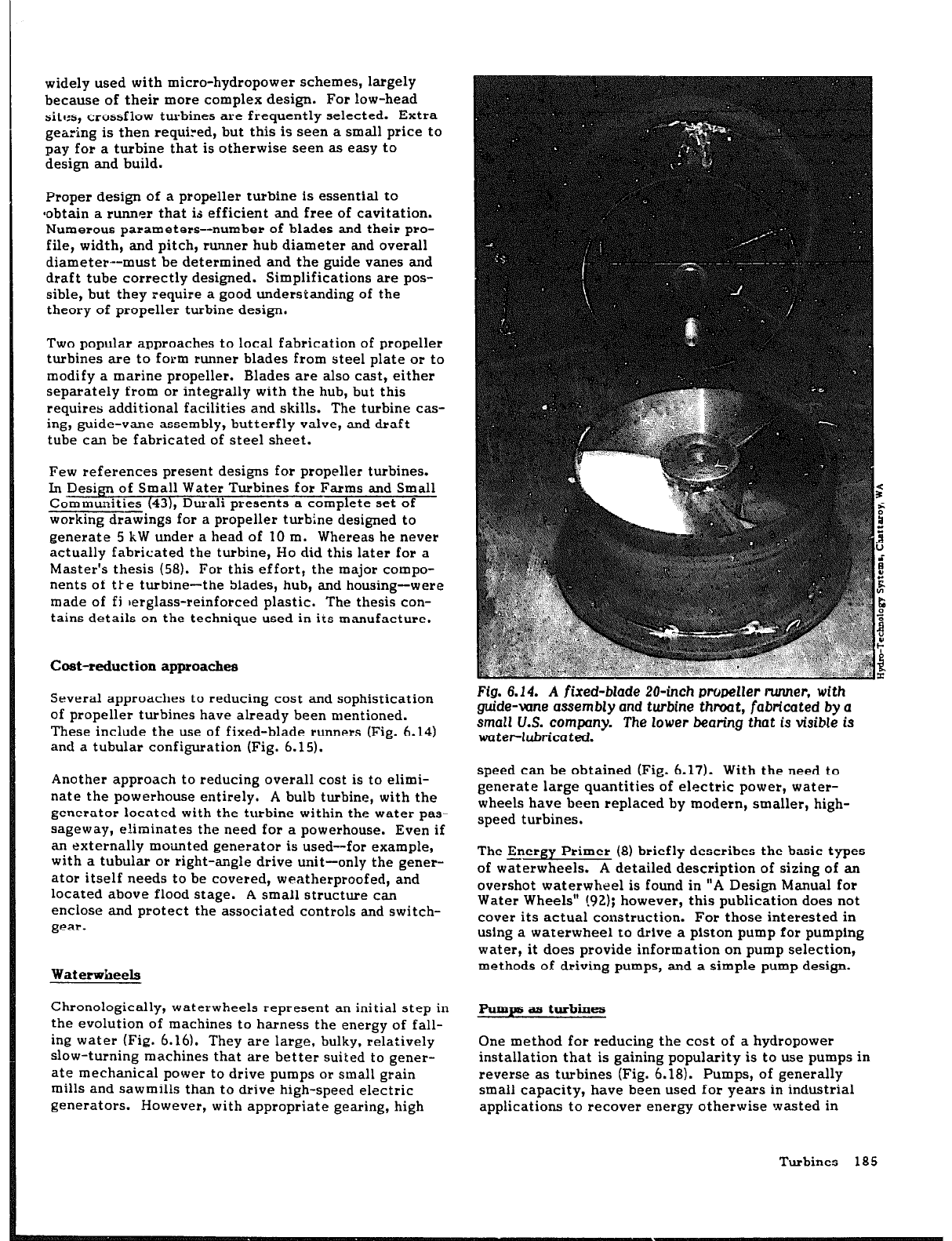
Fig. 6.14. A fixed-blade 20-inch propeller
runner,
with
guide-vane assembly and turbine thraat, fabricated by a
small U.S.
company.
The
lower bearing
that is
visible is
waterlubricated.
speed can be obtained (Fig. 6.17). With the need to
generate large quantities of electric power, water-
wheels have been replaced by modern, smaller, high-
speed turbines.
The Energy Primer (8) briefly describes the basic types
of waterwheels. A detailed description of sizing of an
overshot waterwheel is found in “A Design Manual for
Water Wheels” (92); however, this publication does not
cover its actual construction. For those interested in
using a waterwheel to drive a piston pump for pumping
water, it does provide information on pump selection,
methods of driving pumps, and a simple pump design.
Pumpe a.s turbines
One method for reducing the cost of a hydropower
installation that is gaining popularity is to use pumps in
reverse as turbines (Fig. 6.18). Pumps, of generally
small capacity, have been used for years in industrial
applications to recover energy otherwise wasted in
Turbines 18 5
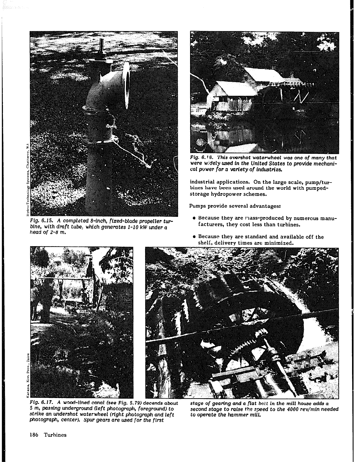
Fig. 6.15. A completed B-inch, fired-blade propeller W-
blne, with draft tube,
which
generates l-10 kW
under a
head
of 2-8
m.
Fig. 6. !6. ‘This overshot waterwheel
WQS one of
many
that
were wk!ely used in the United States
to provide
mechani-
cal power for a variety of industries.
industrial applications. On the large scale, pump/tur-
bines have been used around the world with pumped-
storage hydropower schemes.
Pumps provide several advantages:
o Because they are I-lass-produced by numerous manu-
facturers, they cost less than turbines.
e Because they are standard and available off the
shelf, delivery times are minimized.
Fig.
6.17.
A
waod-lined canal (see Fig. 5.79) decends
about
5 m, passing underground Oeft photograph, foreground) to
stage of gean’ng and a flat tMi in the mill house adds a
strike an undershot waterwheel Crfght
photograph
and
left
second
stage to
mise
the qpeed
to the 40QO
rev/min
needed
to opemte the hammer mill.
photograph,
center).
Spur gears ore used for the first
186 Turbines
prepared by a pump manufacturer that n arkets pumps
as turbines. In addition, the Micro-hydropower Hand-
book (761 summarizes a simpie technique for converting
the-required turbine performance characteristics, based
on site cof-ditions, to the necessary pump characteris-
tics. The method gives only a rough approximation. If
the use ~1” a pump as a turbine is being considered
seriously, the manufacturer should be contacted.
Actual tests are recommended to verify a pump’s per-
f;rmance as a turbine, especially for larger, more costly
units.
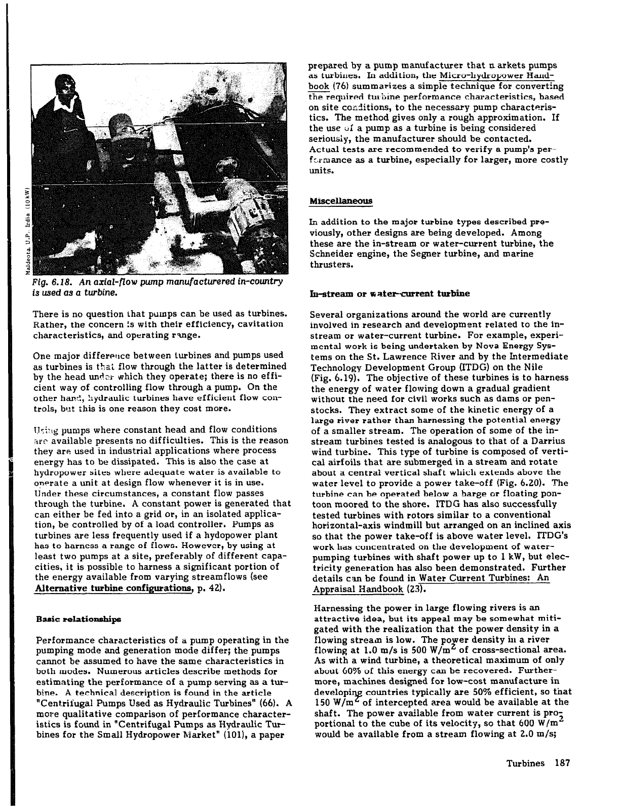
Fig.
6.18. An axial-ftow pump manufacturered
in-country
is
used
as Q turbine.
There is no question that pumps can be used as turbines.
Rather, the concern is with their efficiency, cavitation
characteristics, and operating rulge.
One major difference between turbines and pumps used
as turbines is thai flow through the latter is determined
by the head undci which they operate; there is no effi-
cient way of controlling flow through a pump. On the
other hand, hydraulic turbines have efficient flow con-
trols, but this is one reason they cost more.
lJsi?!g pumps where constant head and flow conditions
arc available presents no difficulties. This is the reason
they are used in industrial applications where process
energy has to be dissipated. This is also the case at
hydropower sites where adequate water is available to
onerate a unit at design flow whenever it is in use.
Under these circumstances, a constant flow passes
through the turbine. A constant power is generated that
can either be fed into a grid or, in an isolated applica-
tion, be controlled by of a load controller. Pumps as
turbines are less frequently used if a hydopower plant
has to harness a range of flows. However, by using at
least two pumps at a site, preferably of different capa-
cities, it is possible to harness a significant portion of
the energy available from varying streamflows (see
Alternative turbine configurations, p. 42).
Basic relationships
Performance characteristics of a pimp operating in the
pumping mode and generation mode differ; the pumps
cannot be assumed to have the same characteristics in
both modes. Numerous articles describe methods for
estimating the performance of a pump serving as a tur-
bine. A technical description is found in the article
“Centrifugal Pumps Used as Hydraulic Turbines” (66). A
more qualitative comparison of performance character-
istics is found in “Centrifugal Pumps as Hydraulic Tur-
bines for the Small Hydropower Market” (lOl), a paper
MisceUaxwous
In addition to the major turbine types described pre-
viously, other designs are being developed. Among
these are the in-stream or water-current turbine, the
Schneider engine, the Segner turbine, and marine
thrusters.
In-stream or watercurrent turbine
Several organizations around the world are currently
involved in research and development related to the in-
stream or water-current turbine. For example, experi-
mental work is being undertaken by Nova Energy Sys-
tems on the St. Lawrence River and by the Intermediate
Technology Development Group (ITDG) on the Nile
(Fig. 6.19). The objective of these turbines is to harness
the energy of water flowing down a gradual gradient
without the need for civil works such as dams or pcn-
stocks. They extract some of the kinetic energy of a
large river rather than harnessing the potential energy
of a smaller stream. The operation of some of the in-
stream turbines tested is analogous to that of a Darrius
wind turbine. This type
of
turbine is composed of verti-
cal airfoils that are submerged in a stream and rotate
about a central vertical shaft which extends above the
water level to provide a power take-off (Fig. 6.20). The
turbine can be operated below a barge or floating pon-
toon moored to the shore. ITDG has also successfully
tested turbines with rotors similar to a conventional
horizontal-axis windmill but arranged on an inclined axis
so that the power take-off is above water level. ITDG’s
work has concentrated on the development of water-
pumping turbines with shaft power up to 1 kW, but elec-
tricity generation has also been demonstrated. Further
details csn be found in Water Current Turbines: An
Appraisal Handbook (23).
Harnessing the power in large flowing rivers is an
attractive idea, but its appeal may be somewhat miti-
gated with the realization that the power density in a
flowing stream is low. The power density in a river
flowing at 1.0 m/s is 500 W/m2 of cross-sectional area.
As with a wind turbine, a theoretical maximum of only
about 60% of this energy can be recovered. Further-
more, machines designed for low-cost manufacture in
developin countries typically are 50% efficient, so that
150 W/m
if
of intercepted area would be available at the
shaft. The power available from water current is pro;
portional to the cube of its velocity, so that 600 W/m”
would be available from a stream flowing at 2.0 m/s;
Turbines
187
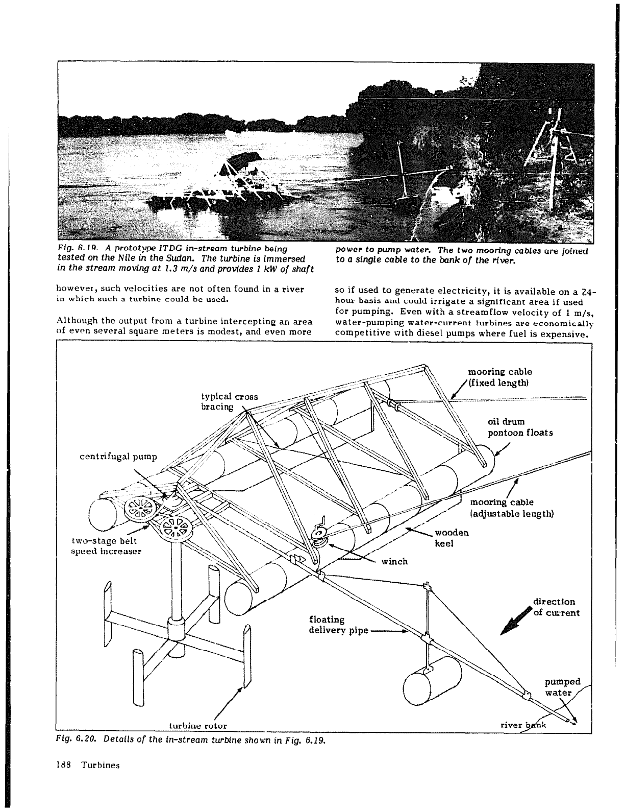
Fig. 6.19. A
prototype
ITDG in-stream turbine being
tested on the
Nile
in the
Sudan. The
turbine is
immersed
.
m the si
!ream moving at 1.3 m/s and provides 1 kW
of
shaft
power to
pump
water. The two mooring
cables are
joined
to u single cable to the
bank
of the river.
howevex, such velociti
howevex, such velocities are not often found in a river
in which such a turbine could be used.
in which such a turbine could be used.
hour ba
so if used to generate electricity, it is available on a 24-
hour basis and could irrigate a significant area if used
for DUU
Although the output from a turbine intercepting an area
Although the output from a turbine intercepting an area
for pumping. Even with a streamflow velocity of 1 m/s,
of evlan several square meters is modest, and even more of evlan several square meters is modest, and even more
water-pumping water-current Lurbines are economically
compet
competitive with diesel pumps where fuel is expensive.
centrifugal pump ,,;
two-stage belt
speed increaser
mooring cable
)
mooring cable
(adjustable length)
turbine rotor
Fig. 6.20. Details of the in-stream turbine shown in Fig. 6.19.
floating
II \
direction
._ -__~--.
of curent
delivery pipe
188 Turbines
At a test site on the Nile, a prototype “low-cost” ttir-
bine had a payback period of less than two dry seasons
when used for irrigating a 0.4 ha riverside plot for vege-
table cultivation.
To increase the power density through the turbine, Nova
Energy Systems has experimented with incorporating
surfaces upsteam of the turbine to increase the effec-
tive velocity of the flow through the rotor. This
increases the cost and complexity of the turbine and is
unlikely to be worthwhile for small. machines using only
a small fraction of the available streamflow
Schneider engine
The Sch,ieider engine is another type of turbine, prima-
rily for lower-head application. This turbine incorpo-
rates a series of straight lifting foils mounted between
two continuous chains, similar to a continuous belt of
Venetian blinds running over a pair of parallel axles.
The large number of moving parts is a concern with this
design.
The U.S. Department of Energy (DOE) has partially
funded the development of a hydropower plant at a
canal drop in the Turlock Irrigation District in Califor-
nia to evaluate the performance of this type of turbine.
After a short time of continuous running, the 140 kW
unit jammed. A prebminary examination revealed the
failure of water seals and a main roller bearing and
cracks in the blade assembly and moving blades. These
failures occurred before the viability of the basic con-
cept was proven (95).
Segner
turbine
A few years ago, in looking for an approach to generat-
ing large: quantities of power than possible by using
traditional mills, yet at a lower cost than using its
crossflow turbines, Balaju Yantra Shala, a Nepali engi-
neering firm and mechanical workshop, resurrected the
Segner turbine, first developed in the mid-1700s (79).
The turbine is comprised of a vertical pipe with nozzles
mounted at the end of radial arms at the bottom. Watet
is fed by a flume into the upper end of the pipe and
released tangentially through the nozzles, as is the case
with a pcpular design for lawn sprinklers. The pipe,
generally 1 to 5 m long, essentially serves as a penstock
hut is free to rotate and is supported by a thrust bearing
at its base. Lower-than-design flows can be accommo-
dated simply by reducing or stopping flow through any
of the nozzles. This type of turbine can handle up to
300 f/s to generate power in the 2-10 kW range. Power
is tapped off the upper end of this rotating pipe section.
Probably the principal difficulty with the Segner turbine
is that it requires a site with a vertical drop.
Marine thrusters
Marine thrusters are propellers used for the propulsion
of ships or the maneuvering of oil rig supports. They
are also being used
for
low-head applications and have
the advantage of being commercial “off-the-shelf”
equipment, which can reduce plant costs. The DOE
funded the installation and testing of a prototype
240 kW unit in the Modesto (California) Irrigation Dis-
trict. The maximum turbine efficiency was about 60%,
possibly caused by mismatching of the turbine with the
site conditions, and some cavitation was also
exper-
ienced (95).
TURBINE SPECIFICATIONS
In requesting price quotations from suppliers of hydrau-
lic turbines and packaged units (Fig. 6.21), it is impor-
tant that as much of the information listed below as
possible accompany each inquiry. Not knowing all this
information may imply that the details of the project
have not been worked out in sufficient detail and that
further work is necessary before firm bids can be solic-
ited. Because a supplier of equipment can spend consid-
erable time preparing a tender, it is best to specify a
single configuration or to minimize the number of alter-
native configurations and extras. An advantage of doing
so is that it is much easier to compare tenders from the
various suppliers.
It is also advisable to avoid unnecessarily overspecifying
the equipment for a site, because this msy prevent the
supplier from proposing equipment that may actually be
better suited to the needs of the developer.
The following is a checklist to help ensure that a site
developer submits the necessary specifications to sup-
pliers of equipment so that they have adequate informa-
tion to prepare tenders:
l
Customer’s name, address, and telephone number or
cable address.
l
An indication of whethek ,n’y an estimate is desired
or whether a full detailel: prllposal or bid is required.
l
If possible, a map or sketch showing the layout of
the proposed site; drawings and photographs of exist-
ing structures and foundations are particularly
important and useful.
For quotes on hydraulic turbines, the following informa-
tion also should be submitted to suppliers:
l
Average net head available. For low-head sites, if
the head vari.ticeably with the flow, also
include the minimum and maximum heads. Penstock
profile and specifications (see below) must also be
described if only the gross head is provided.
l
Flow available for power generation. If virtually the
--7
entire stream is to be used, include a flow-duration
curve based on as many years of data as possible (see
Data proceasing, p. 29) or, if unavailable, provide
some indication of flow variation during a typical
year. Is there provision for storage? If so, how
much?
Turbines 189