Marder M.P. Condensed Matter Physics
Подождите немного. Документ загружается.

Brillouin Zones 213
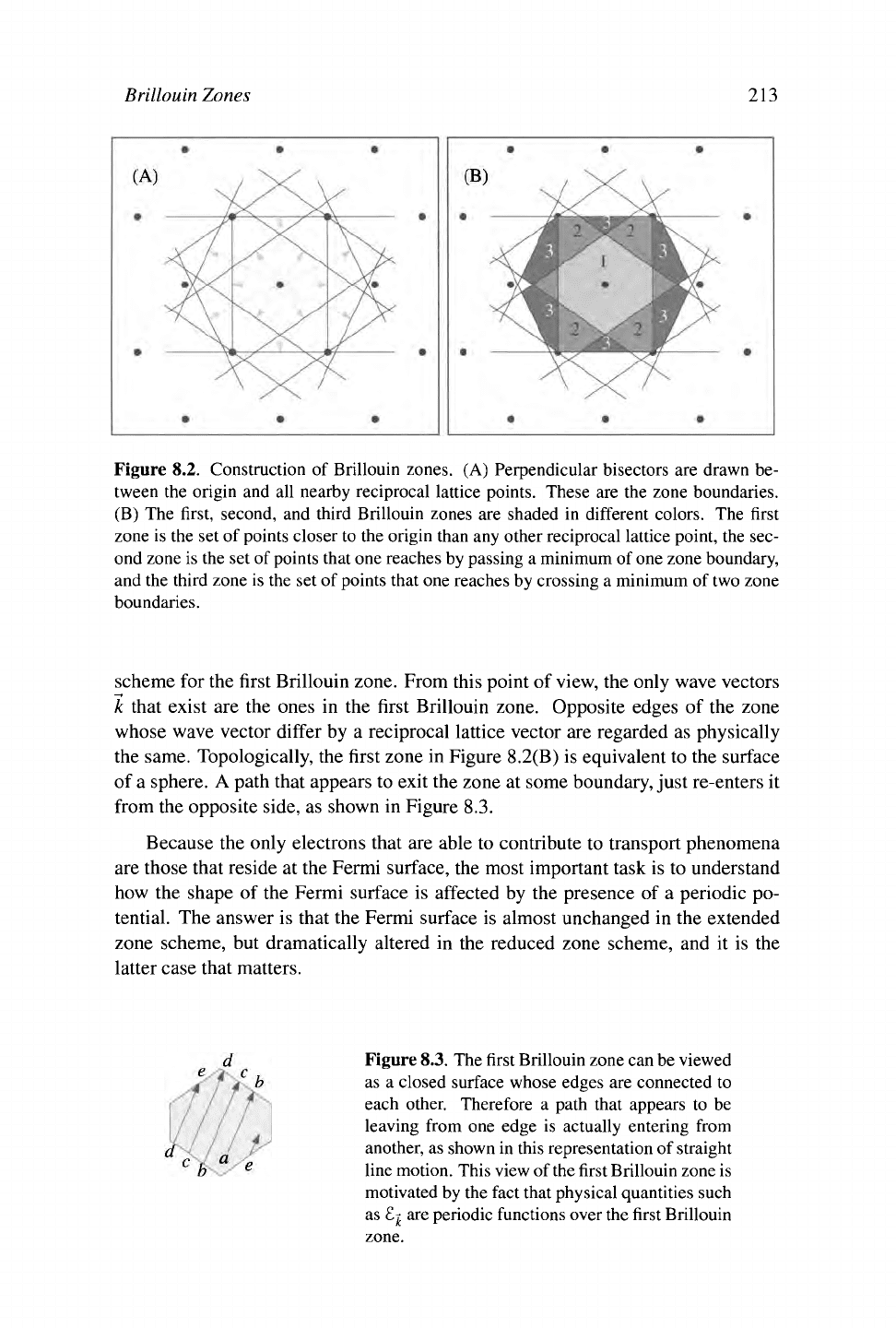
Figure 8.2. Construction of Brillouin zones. (A) Perpendicular bisectors are drawn be-
tween the origin and all nearby reciprocal lattice points. These are the zone boundaries.
(B) The first, second, and third Brillouin zones are shaded in different colors. The first
zone is the set of points closer to the origin than any other reciprocal lattice point, the sec-
ond zone is the set of points that one reaches by passing a minimum of one zone boundary,
and the third zone is the set of points that one reaches by crossing a minimum of two zone
boundaries.
scheme for the first Brillouin zone. From this point of view, the only wave vectors
k that exist are the ones in the first Brillouin zone. Opposite edges of the zone
whose wave vector differ by a reciprocal lattice vector are regarded as physically
the same. Topologically, the first zone in Figure
8.2(B)
is equivalent to the surface
of a sphere. A path that appears to exit the zone at some boundary, just re-enters it
from the opposite side, as shown in Figure 8.3.
Because the only electrons that are able to contribute to transport phenomena
are those that reside at the Fermi surface, the most important task is to understand
how the shape of the Fermi surface is affected by the presence of a periodic po-
tential. The answer is that the Fermi surface is almost unchanged in the extended
zone scheme, but dramatically altered in the reduced zone scheme, and it is the
latter case that matters.
Figure
8.3.
The first Brillouin zone can be viewed
as a closed surface whose edges are connected to
each other. Therefore a path that appears to be
leaving from one edge is actually entering from
another, as shown in this representation of straight
line motion. This view of
the
first Brillouin zone is
motivated by the fact that physical quantities such
as £jj are periodic functions over the first Brillouin
zone.
214 Chapter 8. Nearly
Free
and Tightly Bound Electrons
Example: Brillouin Zone Boundary Intersection for Square Lattice in
Two
Di-
mensions.
Suppose the lattice has two conduction electrons
per lattice site. As discussed after Eq. (7.50), the num-
ber of k states in a Brillouin zone equals the number
of lattice points, and because each k state can accom-
modate precisely two electrons, the volume that the
electrons occupy in k space must equal the volume of
the Brillouin zone. However, for a weak potential, the
shape of the energy surface must be very close to the
shape of the energy surface for free electrons—that is,
a sphere. For a square lattice with lattice spacing a, the reciprocal lattice is also
square, with lattice spacing 2π/α, and the volume of the Brillouin zone is 4π
2
/α
2
.
The Fermi sphere for free electrons must have this same volume, which means
trkf-
= 4π
2
/α
2
=>
kp = 2π/
ν
/
πο =
1.128π/α.
Because at its point of closest ap-
proach the Brillouin zone boundary is at a distance n/a from the origin of K space,
the Fermi surface juts slightly out of the first Brillouin zone.
8.3.1 Nearly Free Electron Fermi Surfaces
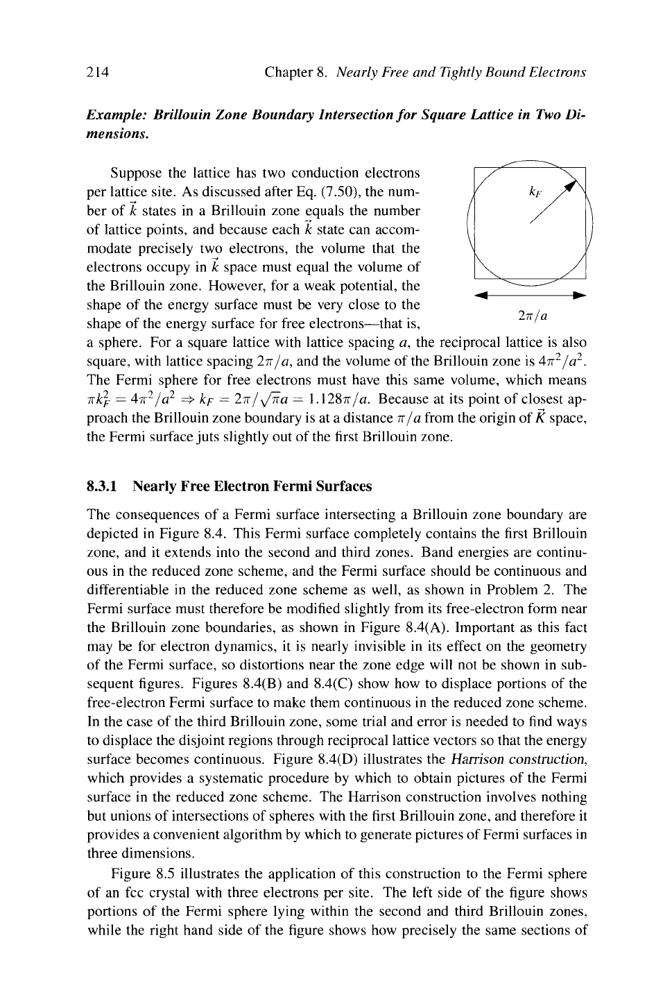
The consequences of a Fermi surface intersecting a Brillouin zone boundary are
depicted in Figure 8.4. This Fermi surface completely contains the first Brillouin
zone,
and it extends into the second and third zones. Band energies are continu-
ous in the reduced zone scheme, and the Fermi surface should be continuous and
differentiable in the reduced zone scheme as well, as shown in Problem 2. The
Fermi surface must therefore be modified slightly from its free-electron form near
the Brillouin zone boundaries, as shown in Figure 8.4(A). Important as this fact
may be for electron dynamics, it is nearly invisible in its effect on the geometry
of the Fermi surface, so distortions near the zone edge will not be shown in sub-
sequent figures. Figures
8.4(B)
and
8.4(C)
show how to displace portions of the
free-electron Fermi surface to make them continuous in the reduced zone scheme.
In the case of the third Brillouin zone, some trial and error is needed to find ways
to displace the disjoint regions through reciprocal lattice vectors so that the energy
surface becomes continuous. Figure
8.4(D)
illustrates the Harrison construction,
which provides a systematic procedure by which to obtain pictures of the Fermi
surface in the reduced zone scheme. The Harrison construction involves nothing
but unions of intersections of spheres with the first Brillouin zone, and therefore it
provides a convenient algorithm by which to generate pictures of Fermi surfaces in
three dimensions.
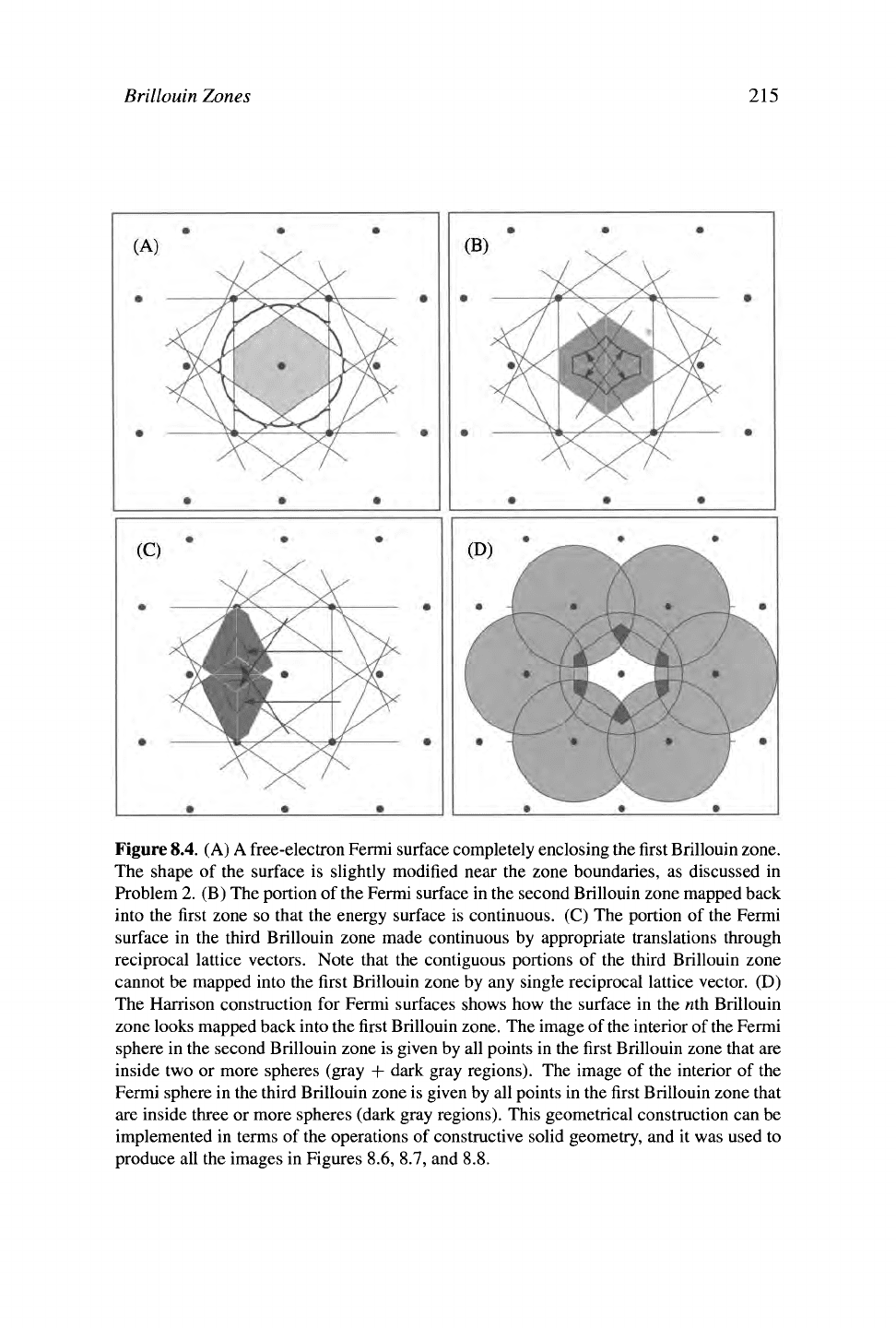
Figure 8.5 illustrates the application of this construction to the Fermi sphere
of an fee crystal with three electrons per site. The left side of the figure shows
portions of the Fermi sphere lying within the second and third Brillouin zones,
while the right hand side of the figure shows how precisely the same sections of
Brillouin Zones 215
Figure 8.4. (A) A free-electron Fermi surface completely enclosing the first Brillouin zone.
The shape of the surface is slightly modified near the zone boundaries, as discussed in
Problem 2. (B) The portion of the Fermi surface in the second Brillouin zone mapped back
into the first zone so that the energy surface is continuous. (C) The portion of the Fermi
surface in the third Brillouin zone made continuous by appropriate translations through
reciprocal lattice vectors. Note that the contiguous portions of the third Brillouin zone
cannot be mapped into the first Brillouin zone by any single reciprocal lattice vector. (D)
The Harrison construction for Fermi surfaces shows how the surface in the «th Brillouin
zone looks mapped back into the first Brillouin zone. The image of
the
interior of
the
Fermi
sphere in the second Brillouin zone is given by all points in the first Brillouin zone that are
inside two or more spheres (gray + dark gray regions). The image of the interior of the
Fermi sphere in the third Brillouin zone is given by all points in the first Brillouin zone that
are inside three or more spheres (dark gray regions). This geometrical construction can be
implemented in terms of the operations of constructive solid geometry, and it was used to
produce all the images in Figures 8.6, 8.7, and 8.8.
216 Chapter 8. Nearly Free and Tightly Bound Electrons
Brillouin zone Extended zone scheme Reduced zone scheme
First Empty Empty
Second
Third
Figure 8.5. Fermi surface for three electrons per site in an fee crystal. On the left the
free-electron Fermi surface is shown in the extended zone scheme, while on the right the
same surfaces are projected back into the first Brillouin zone in the reduced zone scheme.
Brillouin 1 electron/cell 2 electrons/cell 3 electrons/cell
zone
First
Second
Third
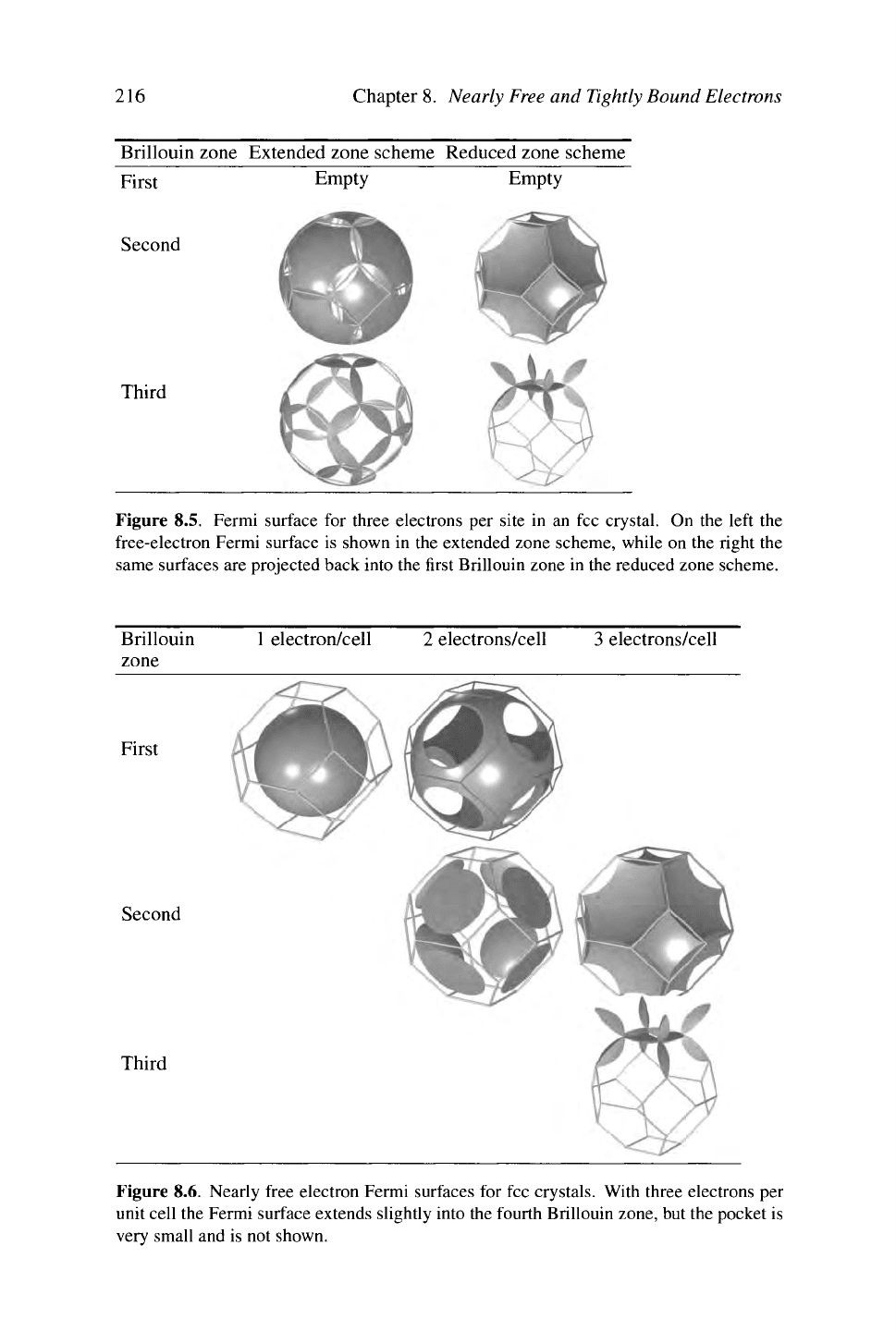
Figure 8.6. Nearly free electron Fermi surfaces for fee crystals. With three electrons per
unit cell the Fermi surface extends slightly into the fourth Brillouin zone, but the pocket is
very small and is not shown.
Brillouin Zones
217
Brillouin
1
electron/cell 2 electrons/cell 3 electrons/cell
zone
First
Second
Third
Fourth
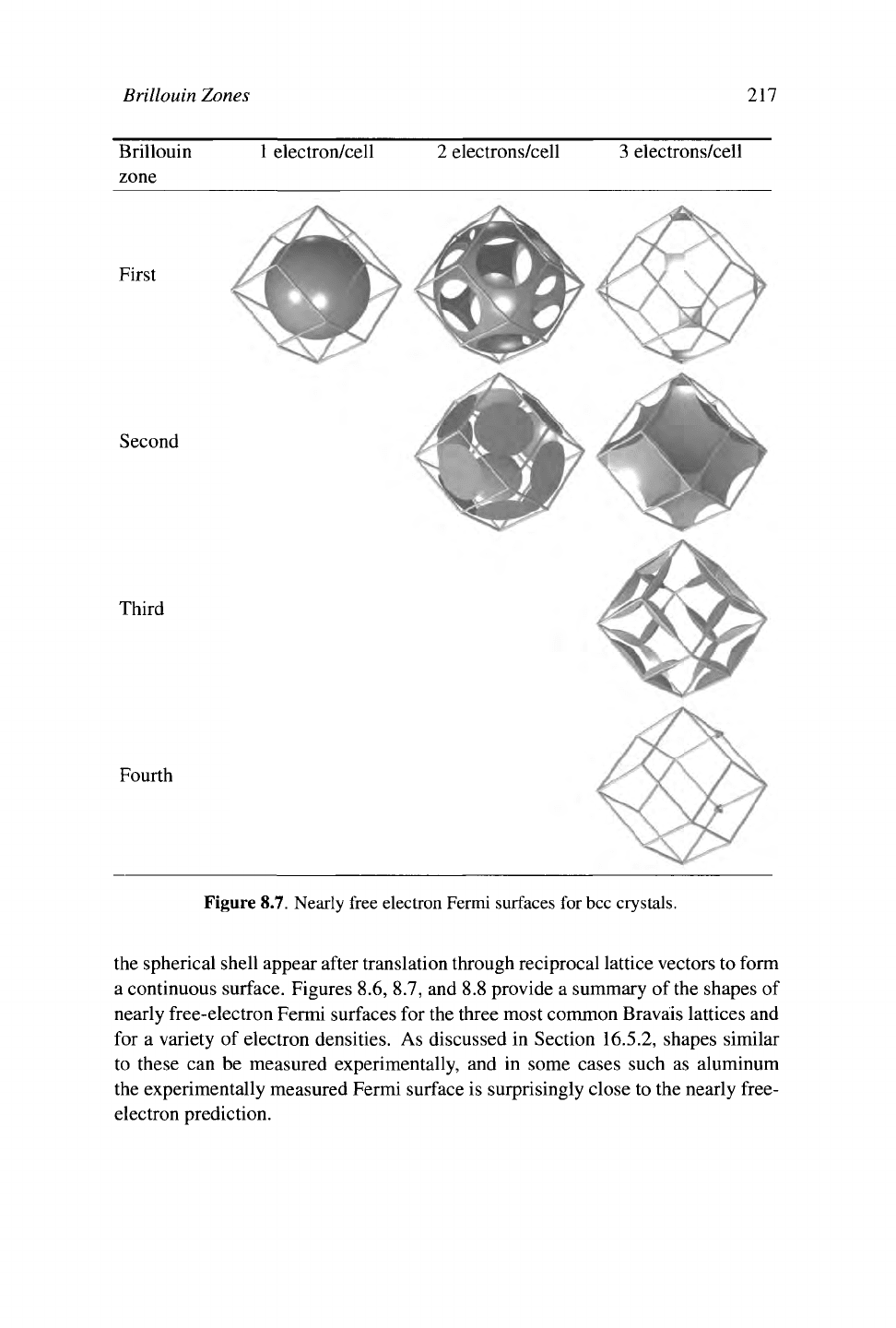
Figure 8.7. Nearly free electron Fermi surfaces for bcc crystals.
the spherical shell appear after translation through reciprocal lattice vectors to form
a continuous surface. Figures 8.6, 8.7, and 8.8 provide a summary of the shapes of
nearly free-electron Fermi surfaces for the three most common Bravais lattices and
for a variety of electron densities. As discussed in Section 16.5.2, shapes similar
to these can be measured experimentally, and in some cases such as aluminum
the experimentally measured Fermi surface is surprisingly close to the nearly free-
electron prediction.
218
Chapter 8. Nearly Free and Tightly Bound Electrons
Brillouin 2 electrons/cell 4 electrons/cell 4 electrons/cell
zone with hep extinction
First
Second
Third
Fourth
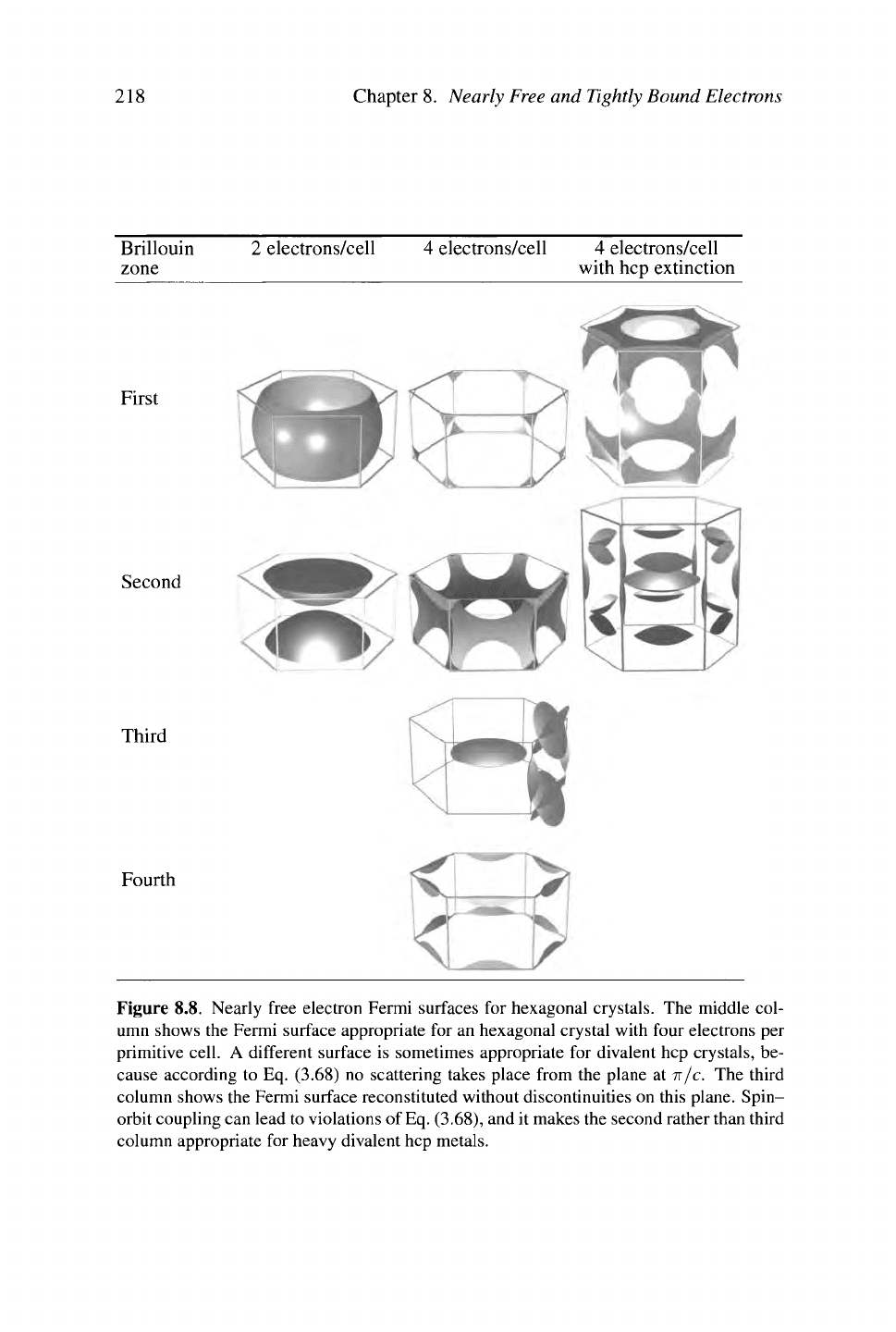
Figure 8.8. Nearly free electron Fermi surfaces for hexagonal crystals. The middle col-
umn shows the Fermi surface appropriate for an hexagonal crystal with four electrons per
primitive cell. A different surface is sometimes appropriate for divalent hep crystals, be-
cause according to Eq. (3.68) no scattering takes place from the plane at π/c. The third
column shows the Fermi surface reconstituted without discontinuities on this plane. Spin-
orbit coupling can lead to violations of
Eq.
(3.68), and it makes the second rather than third
column appropriate for heavy divalent hep metals.
Tightly Bound Electrons 219
8.4 Tightly Bound Electrons
8.4.1 Linear Combinations of Atomic Orbitals
The free-electron gas has served to this point as the main conceptual model for
the study of solids. This choice may seem surprising, for solids are made from
atoms, and viewed as a collection of atoms, a solid seems to bear no relation to
the free-electron gas. Imagine instead starting with a collection of isolated atoms
and slowly bringing them together to form a crystal. Surely in some cases, the
most appropriate approximation must begin with atomic wave functions. Such a
starting point complements without contradicting the one developed until now, and
it is called the tight-binding model.
The idea works best for atoms where most of the electrons are closely held in
closed shells, and the wave functions of the remaining electrons have an amplitude
that decays rapidly away from the nucleus. The following discussion applies to
the electrons of the outer shells, neglecting the ones in the inner core. Let af, be
the wave function for an electron occupying an isolated atom; the index n' lets one
choose more than one electron orbital. The wave function satisfies
K*a*,{r) = -^
2
a*,{r)
+
U*\r)a*,{r)
= £>*<,(?), (8.26)
where the Hamiltonian and energy £f, refer to an isolated atom. Such atomic wave
functions were computed by atomic physicists such as Hartree (1928) starting in
the 1920's, but for the present discussion, their most significant feature is that like
the wave function of the hydrogen atom, they decrease exponentially as one moves
more than a few angstroms from the nucleus.
Now imagine bringing many such atoms together to form a crystal with lattice
vectors R, obtaining the Hamiltonian
Ä = -iv
2
+ [/(?) = --V
2
+ Vt/
al
(r-a (8.27)
2m 2m *—?
R
Using atomic waves functions to solve this Hamiltonian proceeds in two steps.
The first is to build some wave functions that automatically satisfy Bloch's theo-
rem, Eq. (7.36). They are
φ
„'#) = "4 Σ
e^a^r-R).
(8.28)
N *-?
R
A quick calculation verifies that
Φ^Τ +
R) =
-j= £ e
iU
'a
n
,(r-R' + R)
(8.29)
= ^ Σ ^■
(
*
+
*W-#) = *
n
r
k
(7)e
iU
. (8.30)
220
Chapter 8. Nearly Free and
Tightly
Bound Electrons
If it seems too easy to solve the problem with a simple sum, it is. The wave func-
tions Φ are neither normalized, nor eigenfunctions of the Hamiltonian Eq. (8.27).
Just because solutions of Schrödinger's equation must have the form of Eq. (7.36)
does not mean that all functions of this form solve Schrödinger's equation. They
can however be used as trial wave functions and summed together so as to get
the best solution of Schrödinger's equation possible. This means creating wave
functions of the form
n'
To choose the constants
C
nn
>,
use the variational principle in Eq. (B.10). Forming
(-0^|Ä
—
£\Ψ
η
ϊ) and varying with respect to
C*
n
,
gives
This is an eigenvalue equation for E and C„.
0 _ \ r·
;
/φ -Ι3-Γ — £|φ -\ Adding a subscript on £ acknowledges that
^~f " the eigenvector
C„
and eigenvalue £„ are linked.
" The equation can be put in more familiar form
=Φ-
0 = Σ
C
nn< i^n"n' ~ £/|S„'w)
by
™
,1α
Ρ
1
>
ίη
8
from the left
^
S
~'· (8.32a)
n'
where
3i
m
, = (Φ
ηΐ
\π\Φ
ηΙΪ
) and the overlap matrix S
m
,
ΞΞ
(Φ^Φ^). (8.32b)
As a first example of how this formalism develops in practice, specialize to the
case of a Bravais lattice where the the vectors from any lattice point to the nearest
neighbors are denoted by δ, and also specialize to the case of a single s orbital,
meaning that there
is
just a single atomic wave function
a
at
(r)
which is spherically
symmetric. Further computation makes use of the localized nature of the atomic
wave functions. So, when an integral of the form
[ dra
A
{r + R')a*\r +
R)
(8.33)
appears, set it to zero unless R and R' are equal, or are nearest neighbors separated
by one of the vectors δ. Then there are only three overlap
integrals
that appear in
the computation, namely
a= f dra
at
(r)a
at
{r + ô)
U= I dra
at
(r)[U(r)-U'
dt
{r)]a
a
\r).
Recall that u(?) =
^ u
M
(r-
R)
t= Idra
à
\r)[U(r)-U'
d
\r + ì)}a
a
\r + ì). (8.34)
and
These integrals are independent of the direction of
δ
because the atomic wave func-
tion is spherically symmetric. Note that
U'
dt
(r
+ 5) is not necessarily very small
near the origin where a
at
(r) is large. Thinking of the hydrogen atom, for example,
the ground state wave function falls off exponentially, but the potential falls off
only as \/r.
Tightly
Bound Electrons
221
Now return to Eq. (8.32). Since there is only one orbital, the indices n and n'
range over only one value one can call s, and the single constant C
ss
simply drops
out. Thus one can write in the case of a single s orbital that
£ = 5WS„. (8.35)
To evaluate §
ss
write
- " " 1 Γ
§
ss
= V e'HR-R')
—
I dr a
at
(r-R)a
al
(r- R')
The atomic wave
■*-—' N J functions are real.
RR'
= 1 + V
e
ir&
I dr fl
at
(r)a
at
(r + δ) Whenever
Λ
= R' the
J integral gives 1, and
integral gives 1, and
à there are N such
terms.
=
ι+Σ^'*
α
(
8
·
36
)
Next compute the numerator of
Eq.
(8.35):
ÄÄ'
y
I + [U(r) - U
at
(r-R')}a
at
(r-R>)
f ~ v- o*
aa
\r-R)a
a
\r-R') t-iR-â')
= dr y E ig
1
I-
K
) Because a
al
solves the atomic
J ~* N Hamiltonian with eigenvalue £
al
.
RR'
ik-( R R
f
\
+ [ dr Σα*\7-Ε)[υ{?)-υ
α
\7-Ε')}α*{7-ΐί')-
RR'
= E
at
(l+a^2e
iU
)
+ U +
tJ2
eiU
-
Usin
§
8
·
34
· (8.37)
δ δ
Thus one obtains the estimate from Eq. (8.35),
J
k
£r « £
at
+
ά
,^ . (8.38)
Discarding terms of order ali and ai on the grounds that a, t, and U are already
small, one obtains
ε
ι
&ε
Λ
+νί+ίΣ
β
'
1
*·
(
8
·
39
)
Equation (8.39) shows that the energy of tightly bound electrons is mainly given by
the energy of the original atomic orbitals, plus a constant correction due to interac-
tions,
plus a hopping term proportional to t that depends upon k, and describes the
222 Chapter 8. Nearly
Free
and Tightly Bound Electrons
interactions of electrons at one atomic site with neighboring sites. The reason to
use the word "hopping" is that according to Eq. (7.59), electrons with wave vector
k move from site to site at speed
Thus the speed at which electrons move is proportional to t, and vanishes when t
vanishes.
Bandwidth. Letting z be the number of nearest neighbors over which the sum on δ
is performed, the maximum value of £^ is
TX
+ |t|z, and the minimum possible value
is U
—
\t\z. The difference between maximum and minimum energies is defined to
be the bandwidth; half this value is denoted by W, so in this case
2W = 2z|t|. (8.41)
Tight Binding for Lattice with Basis. Using the tight binding method for a
single atomic orbital is a bit of a cheat because the method is originally billed as
variational, and then it is applied to a single function, leaving nothing to vary. For
more complex cases it is necessary to generalize the formalism to accommodate a
lattice with a basis v\ . . . vi. This can be accomplished by writing
φ
η'(?) = -^ Σ e
fkrR
a*,(r-R-v
n
,). (8.42)
R
Now the index n' ranges both over atomic orbitals, and also over basis vectors. The
number of values of n' equals the sum over basis vectors of the number of orbitals
at each site. With this understanding, the computations leading to Eq. (8.32) are
unchanged. Problem 5 shows how to apply the method to obtain an estimate of the
band structure of graphene.
8.4.2 Wannier Functions
Calculations employing atomic orbitals can be put on a much more general footing
by constructing
Wannier
functions. These are a set of orthonormal wave functions
that one can always construct from Bloch functions and which are plausibly local-
ized on atomic sites.
Suppose that one has found all the eigenfunctions of the Hamiltonian and has
arranged them as allowed by Bloch's theorem in the form Eq. (7.44). Then the
Wannier function for electrons from band n centered at lattice site R is defined to
be
(7\R) = W
n
(R 7) = \ e~ ψ - (7) N i
s
'he number of lattice sites, and also the
number of k in the first Brillouin zone, over
which the sum in k is performed.
(8.43)