Mench M.M. Fuel Cell Engines
Подождите немного. Документ загружается.

c06 JWPR067-Mench January 26, 2008 20:1 Char Count=
290 Polymer Electrolyte Fuel Cells
Electrolyte
Catalyst
slurry
Doctor blade
Catalyst layer
Figure 6.4 Tape casting technique for catalyst layer preparation.
tailor the slurry viscosity) are sprayed directly onto the DM or electrolyte surface.
The spray can be applied by a simple nozzle or via electrodeposition, sputter
deposition, or other techniques [3]. The slurry is then held at high temperature in an
oven to evaporate the remaining alcohols. This method has the advantage of being
relatively rapid, but tolerances are not precise compared to other methods.
2. Slurry Tape Casting In this method, a slurry or catalyst layer ink similar to that
used in the spray deposition technique is spread onto the DM or directly onto the
electrolyte via a doctor blade (Figure 6.4). This method produces high dimensional
tolerance but is slower than physical spray deposition and less suitable for mass
production.
3. Decal Method In this technique, thin CLs are cast or spread onto a nonadhesive
medium, and decal transferred onto an electrolyte by hot-press compression (similar
to a clothes iron). This method is suitable for mass production of catalyst layers,
with high tolerance and batch processing capability, although the physical bond
between the electrode and the electrolyte must be carefully maintained.
Diffusion Media The diffusion media (DM) consists of a carbon fiber or woven cloth
macroporous layer and possibly a highly hydrophobic microporous layer (MPL) that we
will treat separately in this text. The flexible DM is a critical component in the PEFC and
was originally developed to enable better electrical contact between the catalyst layer and
lands but really serves four primary functions:
1. To provide electron conduction to and from the catalyst layer. The through- and
in-plane electron resistivity varies with DM type and PTFE content but has been
measured to be around 0.08 ·cm and between 0.055 and 0.009 ·cm, respectively
[4].
2. To provide reactant transport to and product removal from the catalyst layer. A DM
has a typical porosity of 0.7–0.8 and gas-phase permeability of 5–55 Darcys [4].
3. To provide heat transport from the catalyst layer to the current collector. The through-
plane thermal conductivity of cloth and paper DM varies with PTFE content but
has been measured to be between 0.2 and 1.8 W/m · K [5]. At this level it acts as a
thermal insulation on the catalyst layer.
4. To provide mechanical support for the electrolyte structure and avoid tenting into
the channels, which results in poor catalyst–DM conductivity, elevated channel
pressure drop, catalyst layer damage, and local water pooling.
c06 JWPR067-Mench January 26, 2008 20:1 Char Count=
6.1 Hydrogen PEFC 291
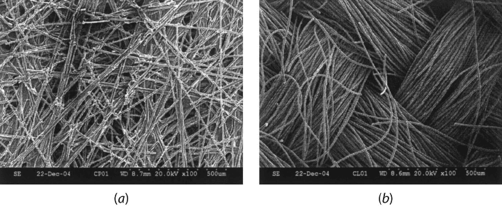
Figure 6.5 SEM of nonwoven fiber paper and woven carbon cloth DM structure: (a) nonwo-
ven fiber; (b) woven carbon cloth. (Image by Soowhan Kim, Penn State Fuel Cell Dynamics and
Diagnostics Laboratory.)
The DM consists of a woven carbon cloth or a nonwoven fiber paper or felt structure
held in a carbonized resin binder to provide good electrical conductivity. In the paper
DM, the resin may have a distribution of very small pores that can also contribute to flow.
Figure 6.5 shows pictures of nonwoven carbon paper and a woven carbon cloth from scan-
ning electron microscopy (SEM), respectively. Carbon cloth materials are manufactured
using weaving technology from the textile industry [4] while carbon paper products are
manufactured using technology similar to that used to manufacture paper products.
The cloth DM are as flexible as any textile, but the paper DM are fairly brittle due to the
presence of thermoset polymer resin and can easily be broken under strain. The webbing
seen in the SEM of the nonwoven paper is not PTFE, but the carbonized resin used to bond
the paper fiber together. Some common properties of various DM are given in Table 6.2.
As discussed, the basic carbon fiber in the DM is hydrophilic and thus will sponta-
neously imbibe liquid water into the porous structure. Because this results in flooding in
H
2
PEFCs, a hydrophobic additive, typically PTFE (Teflon
TM
), is added to prevent pore
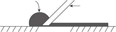
blockage and manage internal water distribution. At the DM surface, the net effect of the
PTFE additive and surface roughness is a generally hydrophobic surface contact angle,
at least from a macroscopic perspective, as shown in Figure 6.6. Since the base carbon
fiber material is hydrophilic, however, the resulting PTFE-treated DM structure is really
a mixed hydrophobic–hydrophilic structure with channels favoring gas-phase and liquid
phase transport, despite the overall hydrophobic surface behavior.
Diffusion Media Compression During assembly, the fuel cell is compressed and the DM
material is deformed under compressive strain. Generally, cloth DM are more compressible
than paper DM, but both materials suffer irreversible strain of 5–20% upon release from
the high compression pressure of 2.75 MPa [4]. Although this compression pressure is
relatively high, significant residual strain has also been observed at normal compression
pressures of 1–2 MPa. Due to the strain, the initial, uncompressed porosity is decreased
under the lands to a compressed value. Assuming all of the compression is a result of lost
c06 JWPR067-Mench January 26, 2008 20:1 Char Count=
292 Polymer Electrolyte Fuel Cells
Table 6.2 Typical Properties of Commonly Used Diffusion Media
Property Cloth Value Paper Value
Thickness 250–450 µm 175–400 µm
Porosity 0.7–0.9 0.7–0.9
In-plane gas-phase permeability
a
10
−12
–10
−11
m
2
10
−12
–10
−11
m
2
Through-plane gas-phase permeability
a
10
−14
–10
−12
m
2
10
−14
–10
−12
m
2
In-plane electrical conductivity 100–200 S/cm 50–200 S/cm
Through-plane specific electrical resistance
a
15–30 m · cm
2
5–20 m · cm
2
PTFE content (by wt %, typical) 5–30% 5–30%
a
Values depend on PTFE content and compression.
pore volume (i.e., the carbon fibers and resin or other additives are incompressible), an
expression for the effective compressed porosity can be derived as
φ
eff
= 1 −
1 − φ
1 − δ
(6.1)
where δ is the fractional strain on the DM material under compression,
δ =
t − t
∗
t
(6.2)
and t is the uncompressed and t
*
the compressed DM thicknesses, respectively. A normal
range of strain on the DM is 10–20% at 1.5–2 MPa compression pressure.
Figure 6.6 Water droplet on hydrophobic paper DM structure. (Image by E. C. Kumbur, Penn State
Fuel Cell Dynamics and Diagnostics Laboratory.)

c06 JWPR067-Mench January 26, 2008 20:1 Char Count=
6.1 Hydrogen PEFC 293
Example 6.1 Typical DM Compressed Porosity Values Calculate a typical range of
compressed DM porosity and the effect on the effective gas-phase diffusivity through the
compressed media.
SOLUTION From Table 6.2, we see a normal uncompressed porosity is around 0.8. Then,
assuming the compressed strain is 10–20% on the DM, from Eq. (6.1), we can calculate
φ
eff
= 1 −
1 − φ
1 − δ
= 1 −
0.2
1 − δ
0.1−0.2
= 0.75
δ=0.2
, 0.78
δ=0.1
Assuming a Bruggeman correlation is appropriate, the fractional gas-phase diffusivity
change for the case of 20% strain is
D
eff
compressed
D
eff
uncompressed
=
Dφ
1.5
comp
Dφ
1.5
uncomp
=
0.75
0.80
= 0.94
So the gas-phase diffusivity under the lands in a compressed DM is retarded by around
6–7% compared to uncompressed values.
COMMENTS: We could extend this analysis to look at the effect of strain on the mass
transfer limiting current density and a variety of other effects. One relevant question re-
garding treatment of the compressive strain is whether or not to consider the compression
uniform over the surface of the DM or only under the lands. There is likely to be some strain
experienced by the entire DM material, not just under the lands, although when viewed
under a microscope, it is clear that brittle paper DM suffer plastic, irreversible damage
upon high compression so that the strain is not uniform over the whole area. Cloth DM
are typically more pliant and suffer greater strain under similar compression pressure, so
strain transmission under the channels is less prevalent for these structures. Another effect
of compressive strain is on the capillary flow of liquid. We know from Chapter 5 that, as the
pore radius decreases in a hydrophobic media, the capillary pressure increases. Therefore,
for the same level of saturation, water in strained DM under the lands will have a higher
capillary pressure and tend to flow lateraly into the channels.
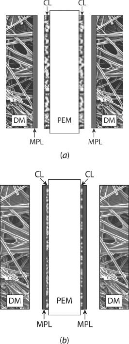
Microporous Layer The addition of a thin (∼5–20-µm-thick), highly dense MPL with
pore sizes of 100–500 nm is commonly used to help water management. There are two
basic types of MPLs employed, as illustrated in Figure 6.7. The slurry-based MPL consists
of (5–20 %) carbon particles, polymeric binder, and 5–20 % PTFE that is applied to the
catalyst side of the DM surface. The other type of MPL is a porous polymer sheet bonded
to the outer surface of the catalyst layer. The MPL can be physically bonded to the catalyst
layer or DM inner surface but resides between the catalyst layer and the DM. The MPL was
originally designed to provide improved electrical conductivity between the catalyst layer
and DM but has since become used primarily to aid in water management for hydrogen and
DAFCs. The MPL structure is highly hydrophobic, and its role in water balance is discussed
in detail later in this chapter. The slurry-based MPL is manufactured in a similar manner to
the catalyst layer. In fact, some MPLs have catalyst in them to help improve performance.
The MPL also functions to protect the catalyst layer from carbon fiber intrusion damage
from the DM.
c06 JWPR067-Mench January 26, 2008 20:1 Char Count=
294 Polymer Electrolyte Fuel Cells
Figure 6.7 Schematic of microporous layers used to enhance water management in PEFCs:
(a) slurry-based MPL consists of carbon particles, polymeric binder, and PTFE that is applied to
the catalyst side of DM surface; (b) porous polymer sheet bonded to outer surface of catalyst layer.
Bipolar Plate/Flow Field The bipolar plate materials and manufacturing techniques used
are also a subject of intense development. The bipolar plate requirements were described in
Chapter 2. Some stack developers and laboratory-scale fuel cells utilize a polymer-sealed
high-conductivity graphite material. The polymer sealing is used to ensure the normally
porous graphite is impermeable to water. For high power density, low weight, and robust
stack design, however, metallic plates are needed. Where graphite flow plates can be as
thin as 2 mm, a stamped metal plate can be almost an order of magnitude thinner, stronger,
inexpensive, and much more manufacturable. The technical difficulties with metal bipolar
plates include difficulty scaling and corrosion, which results in rapid electrolyte degradation
and poor electrical contact resistance.
c06 JWPR067-Mench January 26, 2008 20:1 Char Count=
6.1 Hydrogen PEFC 295
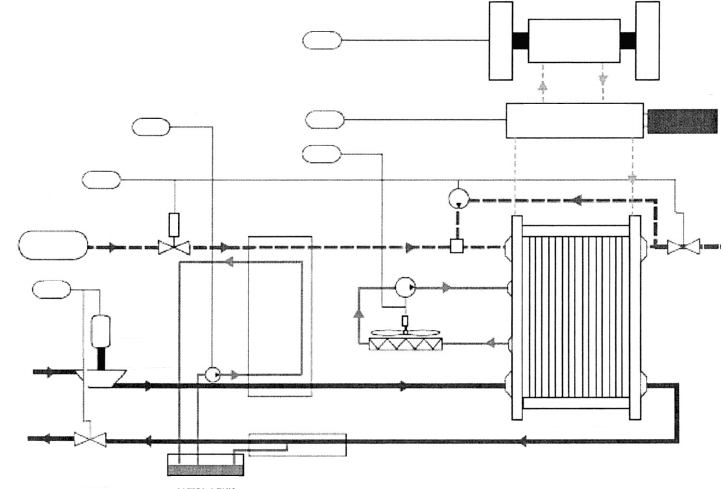
6.1.2 System Components and Subsystems
Within the overall system, the hydrogen fuel cell may occupy considerably less than 50% of
the system volume. The overall hydrogen fuel cell system includes the following subsystems
and control tasks, as illustrated in Figure 6.8:
1. Reactant Storage, Delivery, and Recycling This includes the pumps and blowers
required to supply the stack with prescribed flow rates of fuel and oxidizer and to
recycle unused fuel back into the anode inlet stream. Typically only fuel storage
and recycling are needed as air is used as the oxidant.
2. Humidification This system is responsible for humidification of the flow of re-
actants, as described in the following section. Some systems (especially portable
designs) are designed to be passively humidified and eliminate this subsystem com-
pletely at the expense of reduced performance.
3. Cooling Smaller, low-power portable systems can be passively cooled or even
require insulation. However, systems larger than 1 kWe power typically require
active liquid cooling of the stack to remain within membrane material tolerances
and achieve uniform performance. The choice of coolant is an active area of research.
Distilled water can be used but will freeze at subzero temperatures. Ethylene glycol
(EG) is the coolant of choice for contemporary automotive applications and can
Traction motor control
Temperature control
Humidity control
Hydrogen flow control
Air flow control
Motor
Compressor
Backpressure
valve
Water tank
Water separator
Fuel cell stack
Humidifier
S
Power management
Energy storage
(battery)
Power
conditioning
TM
U
6
U
5
U
4
U
1
U
2
U
3
Hydrogen
tank
Figure 6.8 Schematic of typical hydrogen PEFC system and control tasks. (Courtesy of Manish
Sinha of General Motors.)
c06 JWPR067-Mench January 26, 2008 20:1 Char Count=
296 Polymer Electrolyte Fuel Cells
operate at subzero temperatures, but contact of EG with the electrolyte can cause
irreversible damage.
4. Hydrogen Reformation If a liquid hydrocarbon or alcohol fuel is reformed to pro-
vide the hydrogen gas, a hydrogen generation system is required. The reformation
process is described in greater detail in Chapter 8. For stationary systems, a fuel
reformer is often used. For automotive or portable applications, on-board reforma-
tion is typically avoided due to excessive complexity, cost, and transient control
limitations.
5. Power Conditioning and Control The power from a fuel cell stack is in the form
of direct current (DC) which must normally be inverted to AC and conditioned into
a suitable voltage range to power most electric motors and equipment. The fuel
cell control system is quite complex and is responsible for all system monitoring
and maintaining stable and safe operation though feedback from a variety of flow,
pressure, voltage, current, and temperature sensors, as illustrated in Figure 6.8.
6. Startup Power Systems Fuel cells normally need some external power input to
assist startup. An auxiliary high-power battery to run pumps and heaters during
startup or to provide power to overcome voltage transients and reversals in the fuel
cell stack is often used.
System Humidification A natural question for a student to ask is: Why do we need to
humidify the PEFC at all? After all, it is a net water generation device, and yet so much
of the design is ultimately meant to remove water from the cell. Since the fuel cell has
a precarious balance between a moist electrolyte needed for high ionic conductivity and
a flooded cell that degrades performance, it is entirely possible that some sections of the
same fuel cell or individual plates in a stack will be overly dry and other sections in the
cell or different plates in a stack will be flooded. Because of this, some humidification is
typically needed at the inlet of the fuel cell to ensure adequate performance. Addition-
aly, strong humidity gradients in the electrolyte can result in internal stresses that limit
durability.
Humidification is accomplished by two main approaches, passive and direct humid-
ification. In passive humidification, the water generated by reaction is used to maintain a
proper moisture balance and humidify the incoming flow without external power. In active
humidification, a separate humidifier is used to directly provide the humidification of the
incoming flow with stored or recycled water.
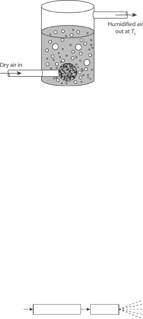
Methods of Active Humidification Active humidification requires a discrete, external
humidification system. In a laboratory environment, a sparge-type humidifier, as illustrated
in Figure 6.9, is often used. In this system, gas is sparged through a porous rock and
into heated water to absorb moisture before entering the fuel cell. This system is not
useful outside the laboratory because it is dependent on orientation and almost never
100% efficient. Care must be used to ensure proper humidification is achieved and careful
calibration is neccessary.
In a membrane humidification system, dry air is forced through a moist membrane with
small pores to absorb moisture. The membrane humidification system can have very high
efficiency but also has a higher pressure drop compared to sparge systems. A third type of
c06 JWPR067-Mench January 26, 2008 20:1 Char Count=
6.1 Hydrogen PEFC 297
Figure 6.9 Schematic of sparge-type laboratory humidifier.
active humidification is direct injection of liquid droplets (Figure 6.10). This technology
is based on gasoline injection systems. Additional advantages of this approach are that
the liquid added to the flow is precisely metered, and the energy required to evaporate the
droplets can be used to cool the flow. This can be especially useful in pressurized systems
where flow from the compressor can be at significantly elevated temperature.
Methods of Passive Humidification Because the humidification system is an additional
complexity and the fuel cell itself is a net water producer, there is a tremendous potential to
develop passive humidification systems that eliminate parasitic humidification altogether.
One such method of passive humidification is the use of an external membrane to absorb
and transfer moisture from the cathode effluent, as illustrated in Figure 6.11. At the exit,
an absorbent membrane captures the water through condensation on the cooler surface,
and a concentration gradient between the dry inlet flow and wet effluent produces a net
flux into the inlet flow, recirculating the product moisture. This approach can also be
adapted for larger stacks by filtering condensate water into a central condensation collection
plenum, and then used to supply a membrane humidifier, or by exchanging the exit water
through a membrane to directly humidify incoming flow, so humidifier water refilling is
unnecessary.
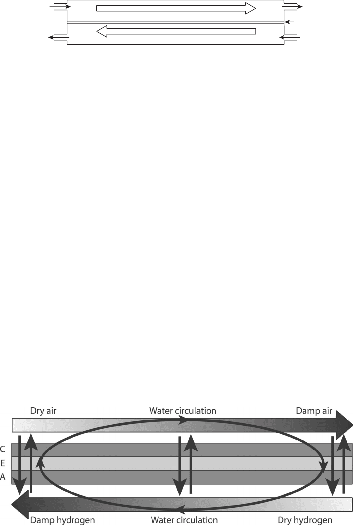
Water can also be internally recirculated, as shown in Figure 6.12, with the use of a
counterflow arrangement. Although the net water generated that must ultimately be removed
from the stack is the same, a counterflow arrangement facilitates transport of water from
the wet cathode exit, through the electrolyte, to the dry anode inlet. Similarly, at the anode
exit, the moisture balance is reversed, and diffusion drives the flow of moisture toward
InjectorInjection pump
Water in
Figure 6.10 Schematic of direct injection humidification system.
c06 JWPR067-Mench January 26, 2008 20:1 Char Count=
298 Polymer Electrolyte Fuel Cells
To atmosphere
To fuel cell
Atmospheric air in
Humidified product
gas from fuel cell
Inlet air getting warmer and more humid
Outgoing air cooling and losing water
Membrane
Figure 6.11 Passive humidification with external water recirculation. This system can be used to
recycle water produced by fuel cell stack into incoming fuel or oxidizer stream, eliminating need for
separate water storage container.
the cathode. This internal recirculation through a counterflow arrangement is utilized on
many portable applications to eliminate the humidifier and on larger systems to reduce the
humidification load required. The high humidity gradients are not generally suitable for
long-term use, however.
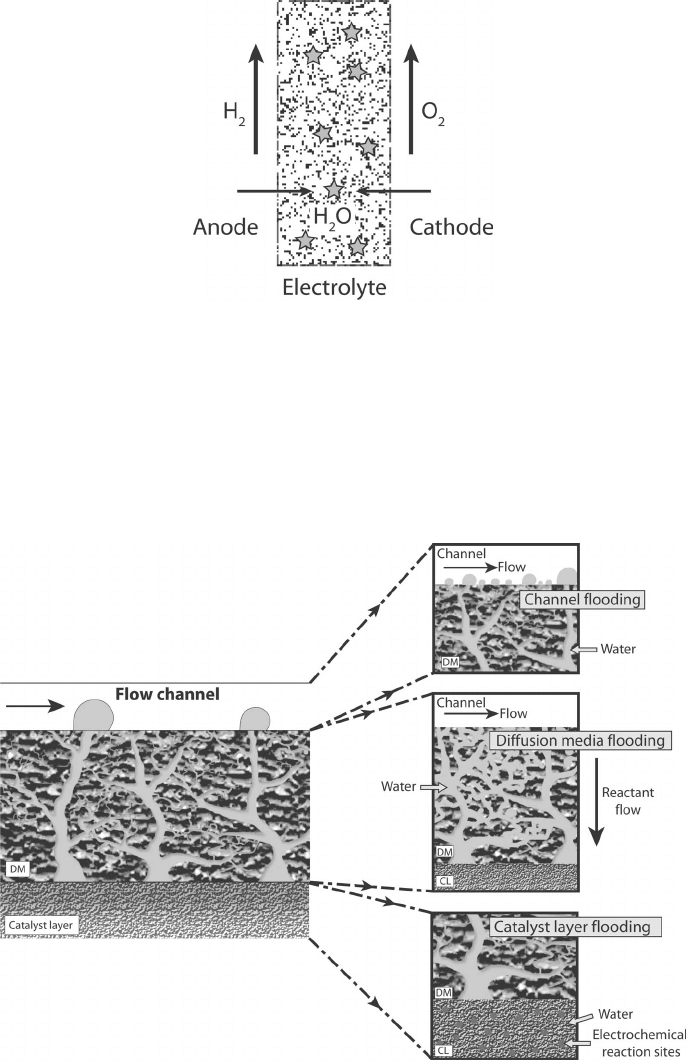
In another novel method of internal humidification, originally proposed by Watanabe
et al. [6], platinum particles are embedded into the main electrolyte. The crossover hydrogen
and oxygen react on these surfaces, generating water and maintaining membrane hydration
despite low external humidity, as illustrated in Figure 6.13. This has the added benefit of
converting crossover gases into water before reaction on the electrodes. A variation of this
concept has been used in an attempt to generate higher temperature membrane materials by
using a water-absorbent additive such as SiO
2
to the perflourinated membrane material, so
that it retains moisture in a higher operating temperature membrane [7]. Various composite
membrane technologies have had some success in achieving a higher conductivity in low-
humidity environments.
6.2 WATER BALANCE IN PEFC
A key element in PEFC performance is the water balance. There is a complex relation-
ship between moisture content and performance in PEFCs. For high ionic conductivity,
the polymer electrolyte membrane must have high moisture content [8]. However, as dis-
cussed in Chapter 5, liquid accumulation can restrict reactant availability at the electrode,
Figure 6.12 Passive humidification with internal water recirculation. This counterflow configura-
tion is used for portable and underhumidified arrangements.
c06 JWPR067-Mench January 26, 2008 20:1 Char Count=
6.2 Water Balance in PEFC 299
Figure 6.13 Passive humidification via internal membrane water generation from embedded plat-
inum particles.
resulting in performance loss. Performance loss resulting from liquid water accumulation
is generically referred to as flooding. More specifically, flooding can occur as a discrete
event in the anode or cathode catalyst layers, DM, or flow channels, as illustrated in
Figure 6.14. At low current, anode and cathode side-channel level flooding from slug
blockage has been observed [9] as a result of the inability to remove slugs from the
Figure 6.14 Schematic of possible locations of flooding in PEFC including catalyst layer, diffusion
media, and channel level flooding.