Mench M.M. Fuel Cell Engines
Подождите немного. Документ загружается.

c06 JWPR067-Mench January 26, 2008 20:1 Char Count=
330 Polymer Electrolyte Fuel Cells
DM
Channel Channel Channel
Capillaries Water reservior
Figure 6.39 Schematic of United Technologies porous plate fuel cell design concept, based on
[35].
Mesh designs are another attempt to reduce parasitic pressure losses, which can con-
sume up to 30% of the gross system power. Since flow tends to follow the path of least
resistance, the mesh design can leave corner areas as deadzones. The spiral design is an
attempt to have exit channels, typically high in humidity, adjacent to inlet channels, so
that moisture can be exchanged in-plane between channels, reducing the humidity load
required for optimal performance. Unfortunately, aligning channels from near the inlet
with channels near the output is rarely wise because the pressure drop in the channels will
induce unintentional reactant bypass between the lower pressure exit and higher pressure
inlet, leaving portions of the active area without sufficient reactant.
The metal foam is a highly porous structure designed to completely eliminate the
channel/land structure of the flow field and landing combination. Instead, a highly porous,
conductive material is used as the flow field. This system has similar draw backs to the
mesh design. Radial designs have been proposed for use in portable applications. Fuel is
pumped through an interior annulus of the radial stack, and air diffuses along the cathode
surface. The radial design minimizes the diffusion distance of the air, which is helpful when
no active pump is used.
An emerging concept in flow field design is that of asymmetric channel properties.
In this type of design, a basic pattern is adopted, such as the parallel–serpentine combi-
nation. However, varying channel–land ratios or channel depths are applied to maximize
performance and stability. This advanced design approach requires a deep understanding
of the engineering trade-offs and nonuniformities along the flow field so that the unique
features can be properly implemented. For example, the channel width can be varied along
the channel or between various channels to control pressure drop, flow distribution, or
liquid water accumulation inside the flow field. The disadvantage of this approach is that
manufacture of the flow fields is generally more complex.
Stack Orientation and Flow Direction In PEFCs, the anode and cathode flow fields
should have some similar landing locations, so that most of the lands of the anode press
against the lands of the cathode, forming a good overall compression and reducing sag
of the membrane electrode assembly (MEA) into channels. Although flow in the fuel cell
porous media is dominated by capillary forces, the channel-level and manifold liquid flow
is strongly influenced by gravitational forces. If the fuel cell stack is oriented in a nonneutral
position with gravity (e.g., the fuel cell plates are aligned vertically or at an angle), the
inlets should be higher than the exits to allow water slugs to flow from the cell into the exit
manifold. Additionally, the flow field should avoid local low points, where the water can
pool in the channels due to gravitational effects. The flow should either be gravity neutral
or follow a path of continually decreasing height with respect to gravity from inlet to exit
for the anode and cathode.
c06 JWPR067-Mench January 26, 2008 20:1 Char Count=
6.3 PEFC Flow Field Configurations and Stack Design 331
(a)
Anode in
Cathode in
(b)
Anode in
Cathode in
Figure 6.40 Schematic of single channel (a)coflowand(b) counterflow design. In stack plates,
the flow is often not exactly one or the other, but a mixture, since the anode and cathode flow designs
can be quite different from one another.
The direction of the fuel and oxidizer flow can be coflow, counterflow, or a mixture of
both. In the coflow case, the fuel and oxidizer inlets follow the same path, with reactants
depleting from inlet to exit, as shown in Figure 6.40a.
For underhumidied inlets, the qualitative humidity, performance, and mole fraction dis-
tributions are illustrated in Figure 6.41. The flooding shown will generally only occur after
the saturation limit is reached, which may not actually occur depending on the operational
parameters, such as flow rate, temperature, and inlet humidities on the anode and cathode.
In the counterflow case, the inlets of the oxidizer and fuel are at opposite ends and flow
against each other, as shown in Figure 6.40b. Depending on the stack and plate design, the
flow pattern may not be completely coflow or counterflow and is some combination of both.
The reasons for choosing a particular flow geometry are varied. The traditional view has
been to design the fuel cell flow channel to minimize variations in the properties; that is,
the coolant flow channel would be designed to minimize temperature gradients in the fuel
cell. However, if a cell is properly designed to take advantage of pressure, temperature, or
humidity gradients, these gradients can be used to effectively manage the water balance or
cooling requirements. For underhumidied inlets, the qualitative humidity, performance, and
mole fraction distributions are illustrated in Figure 6.42. For nonbalanced inlet humidity
combinations, the local distributions can be more complex, as discussed in Section 6.6. In
i (flooding loss)
RH saturated limit
y
O
2
, y
H
2
iRH
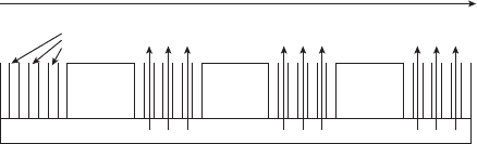
Figure 6.41 Schematic of typical distributions of species, current, humidity, and temperature in
PEFC with purely coflow design and underhumidified anode and cathode inlets. The flooding loss
portion does not necessarily have to occur, depending on inlet conditions, temperature, etc.
c06 JWPR067-Mench January 26, 2008 20:1 Char Count=
332 Polymer Electrolyte Fuel Cells
i
RH anode/cathode
y
O
2
, y
H
2
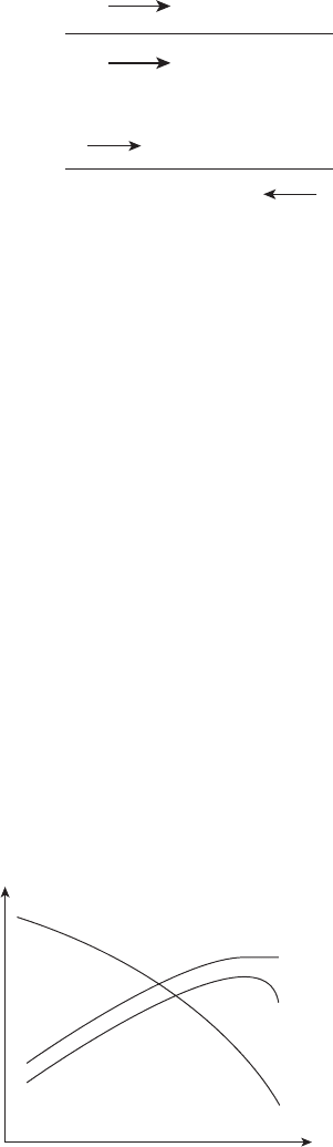
Figure 6.42 Schematic of typical distributions of species, current, humidity, and temperature in
PEFC with counterflow design with underhumidified anode and cathode inlets.
some cases, the mole fraction of the hydrogen can actually increase along the flow path if
the inlet flow is dehumidified along the flow path.
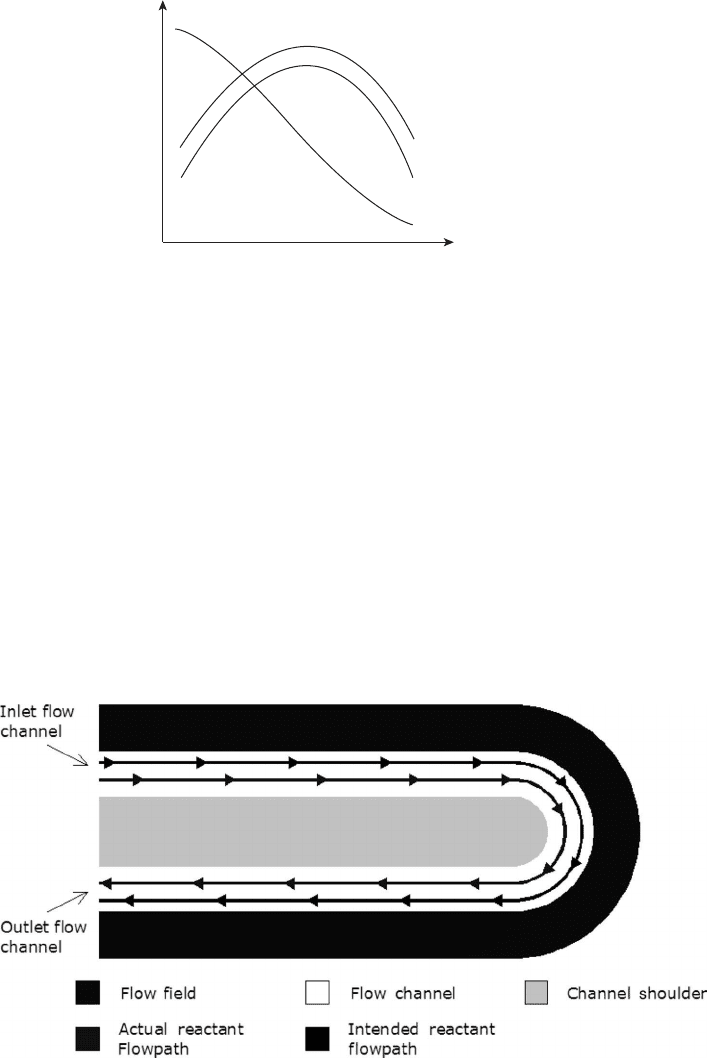
Unintentional Reactant Flow Bypass Reactant bypass, or in-plane gas shorting, is de-
scribed as a phenomenon of unintentional reactant penetration through the backing layer,
underneath a current collecting land, and into another flow channel. Optimal performance
without bypass is shown in Figure 6.43, where the reactant gases follow the intended flow
path and utilize the fuel cell’s entire active area.
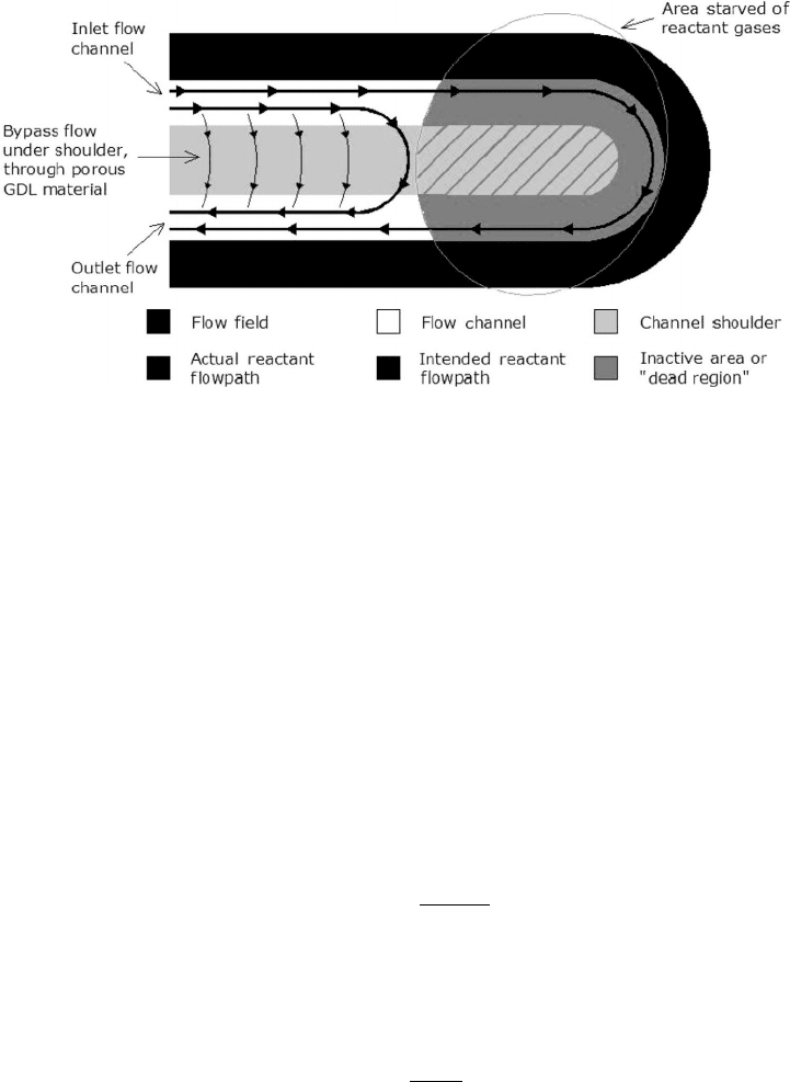
In the case where bypass occurs, portions of the cell’s active area do not continuously
receive a sufficient amount of reactants and a local dead zone is created, as illustrated in
Figure 6.44. The bypass phenomenon is commonly observed in fuel cells with serpentine-
style flow fields and may be caused by a variety of circumstances in a fuel cell, including
poorly designed flow field plates, water droplet accumulation, poor assembly, and large
Figure 6.43 Schematic of normal reactant flow without bypass around 180
◦
switchback channel
turn. (Adapted from Ref. [36].)
c06 JWPR067-Mench January 26, 2008 20:1 Char Count=
6.3 PEFC Flow Field Configurations and Stack Design 333
Figure 6.44 Schematic of unintentional bypass that leaves a dead zone. The bypass can be a result
of poor compression, excessive channel pressure drop, or poor flow field design. (Adapted from
Ref. [36].)
pressure differentials along a given flow channel [36–39]. In terms of the flow plate design,
if some flow channels with a high local pressure (e.g., inlet locations) are adjacent to
channels with lower pressure (e.g., exit locations), excessive shorting can occur. The spiral
design in Figure 6.36 is an example of this. As the flow comes into the cell and goes into
the second turn, it is adjacent to the exit portion of the channel that is at the lowest overall
pressure in the flow field. In this case, resultant pressure mismatch can lead to significant
reactant bypass and low performance.
The amount of bypass flow is controlled by the ratio of the pressure drop through
the channel to the pressure drop through the DM. If the pressure drop through the DM to
the bypass emergence point is relatively low compared to the pressure drop through the
channel, significant bypass will occur. Assuming laminar flow, the pressure drop though
the channel a distance L from the bypass location to the bypass emergence point can be
derived from laminar flow theory [40]:
P
flow path
=
32LVµ
d
2
h
(6.36)
where V is the channel bulk flow velocity and we have ignored turbulent, entrance, or
secondary flow losses. An estimate of the pressure drop through the porous backing layer
can be estimated with Darcy’s law [41]:
P
Backing
=
U
ave
µ
k
S (6.37)
where µ is the viscosity of the fluid, U
ave
is the bulk average velocity through the porous
medium, S is the porous medium thickness in the direction of flow (equivalent to the land
width), and k is the permeability of the backing layer. The DM permeability is a highly
nonlinear function of porosity, as discussed in Chapter 5.
c06 JWPR067-Mench January 26, 2008 20:1 Char Count=
334 Polymer Electrolyte Fuel Cells
A dimensionless parameter termed the bypass ratio (BPR) can be defined as the ratio
of pressure drop through the channel to the backing layer [42]:
BPR =
32LVk
d
2
h
U
ave
S
(6.38)
Obviously, the channel bulk flow velocity and the average bypass velocity U
ave
will be
related, but the basic physics can be understood with this simple relationship. If BPR
is much greater than unity, significant bypass should occur; if BPR is much less than
unity, significant bypass can be avoided. Channel pressure, flow viscosity, and temperature
should have little or no effect, while the hydraulic diameter, channel length, land width,
DM permeability, and liquid saturation are the key controlling physical parameters.
Stack Design Considerations for Portable and Automotive Applications The ideal fuel
cell stack design has the following qualities:
1. Compact design for maximum power density.
2. Proper flow manifolding to deliver flow evenly to all fuel cells in the stack without
reversal of flow.
3. Proper sealing of reactants and coolant channels.
4. Low-cost, robust components.
5. High durability under a variety of operating environments.
6. Simplified purge and drainage of liquid water on shutdown.
For stationary and automotive PEFCs, the most common stack design is simply a vertically
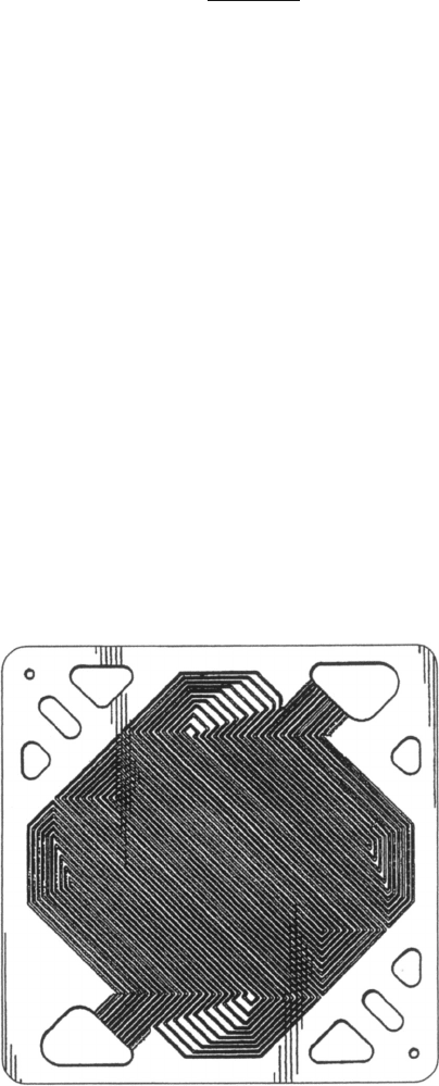
stacked fuel cell plate configuration. Figure 6.45 shows an individual fuel cell flow plate
Figure 6.45 Serpentine stack plate field design showing manifolding of coolant, hydrogen, and air
through middle of cell arrangement. (Reproduced with permission from Ref. [37].)
c06 JWPR067-Mench January 26, 2008 20:1 Char Count=
6.3 PEFC Flow Field Configurations and Stack Design 335
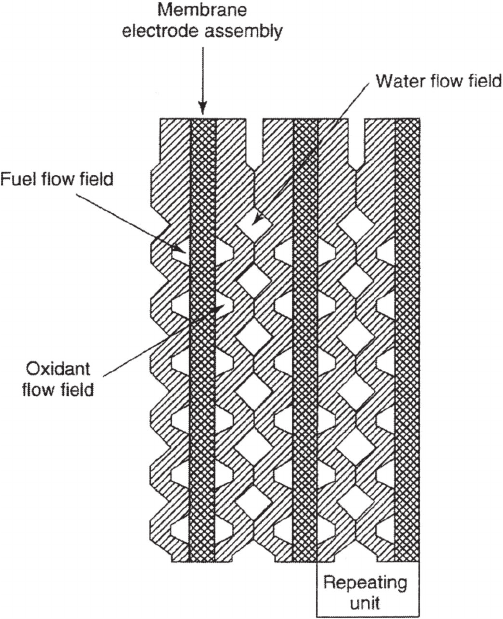
Figure 6.46 Fuel cell corrugation stacking for compact design. (Reproduced with permission from
Ref. [37].)
used in a hydrogen PEFC flow field design patented by Ballard. Typical power densities of
the fuel cell stack are now on the order of 1.3 kW/L and higher not including the balance
of the plant.
Typically, coolant flow channels are placed every or every second fuel cell to pro-
vide uniform heat removal and temperature distribution. Cells are stacked as efficiently
as possible to provide a compact design. One way to increase stacking density is with
corrugated designs, as illustrated in Figure 6.46. The corrugated design is very efficient for
the stack, but sealing and proper flow manifolding are difficult to achieve. Coolant flow
channel designs are typically simpler than the hydrogen or air flow field designs but should
be tailored in concert with the anode and cathode flow fields to achieve proper heat and
water management.
For portable fuel cells, as used in small consumer electronics, the shape of a common
vertical stack is usually not desirable to replace many of the thin batteries currently used.
Therefore, a planar stack design is often used, as shown in Figure 6.47. In this design,
the passive air flow cathode faces the open air, and the perforated metal cover serves as
the current collector. The main issue with this configuration has been limitations in the
effectiveness of the electrical connection between adjacent cells, since the path length for
electron travel is longer than in a traditional vertical stack design.
c06 JWPR067-Mench January 26, 2008 20:1 Char Count=
336 Polymer Electrolyte Fuel Cells
Anode
H
2
flow
Anode 1 Anode 2 Anode 3
Cathode 1 Cathode 2 Cathode 3
Bipolar plate/cell
interconnect
i
ii
i
Cathode
air flow
Figure 6.47 Planar stack design with open cathode design for natural breathing. Note the use of
cell-to-cell interconnects instead of structural bipolar plates common to PEFC designs.
Several different radial fuel cell stack designs have been developed. The primary reason
to develop a radial system is to have the same form factor as a common battery. The radial
design is typically fed fuel from an inner hollow core and air from the ambient around the
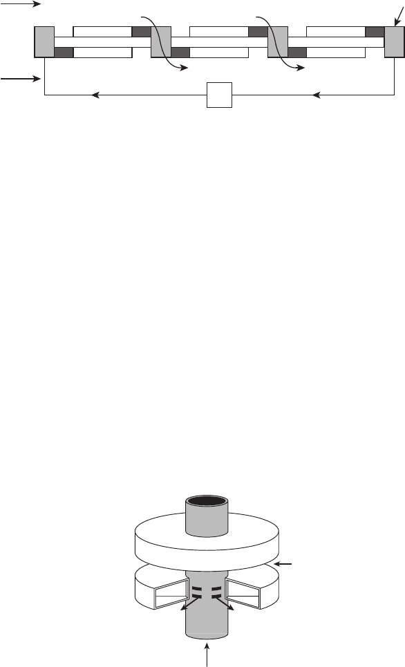
unsealed cathode edges of the cell, as shown in Figure 6.48. An advantage of the radial
design in this instance is that the diffusion path length is minimized.
Many other portable designs exist, although almost all follow the basic planar, radial,
or conventional stack design with some modifications.
Stack Manifold Flow One of the most difficult engineering challenges in fuel cell stack
design is the proper manifold design for fuel, oxidizer, and coolant flow. The manifold
design challenge centers around three main constraints:
1. The manifold must be compact to minimize stack volume yet have minimal pressure
loss.
2. The manifold must deliver flow evenly to all fuel cell plates, or flow maldistribution
can occur, leading to significant performance degradation.
3. The manifolds must be properly sealed to prevent mixing of air, fuel, and coolant.
H
2
in
Anode
Anode
Cathode
Cathode
Air in
H
2
out
Figure 6.48 Schematic of portable design with radial open channels. The hydrogen flows upward
through the inner distribution tube and outward into the closed anode chambers. The cathode flow
field is an open structure, drawing air in from the ambient. Interconnects are not shown for clarity,
and different variations of this concept exist.
c06 JWPR067-Mench January 26, 2008 20:1 Char Count=
6.3 PEFC Flow Field Configurations and Stack Design 337
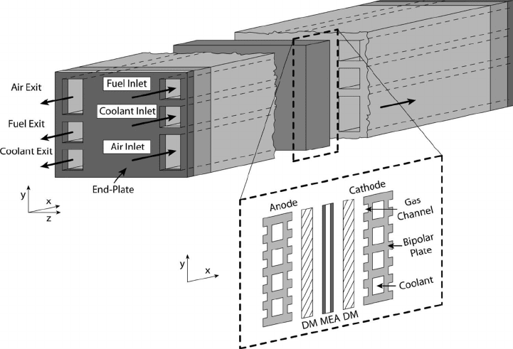
Figure 6.49 Schematic of chimney design utilized in most stack configurations for flow manifold-
ing. Generally, an air, hydrogen, and coolant inlet and outlet chimney is used.
The manifold design challenge is further exacerbated by the fact that most fuel cell
stacks contain over 100 fuel cells in series. In PEFCs, the presence of liquid water presents
a multiphase flow and instability problem that further complicates design. Despite the
myriad flow field patterns, the vast majority of vertical stacks employ some sort of chimney
manifold, as illustrated in Figure 6.49, with flow for coolant, fuel, and air running through
the periphery or the middle of the stack. The manifold exchanges between the individual
cells must be sealed with O-rings, gaskets, or permanent glues to prevent crossover or
coolant leakage.
In the chimney manifold design, the pressure drop in the manifold must be much less
than the pressure drops through the flow field plates, so that flow is evenly distributed
among the plates. In an ideal situation, each parallel flow field plate would have an identical
pressure drop, providing uniform flow distribution. However, multiphase flow will exisit
in PEFC operation during startup, shutdown, and even regular operation, and assembly
conditions or DM sag can result in slight difference in plate-to-plate or channel-to-channel
pressure drop. The flow inside an exit manifold is highly complex and nearly impossible
to analytically describe. The presence of liquid water droplets in the flow fields increases
the pressure drop for droplet removal and causes transient pressure variations between the
flow field plates in the stack.
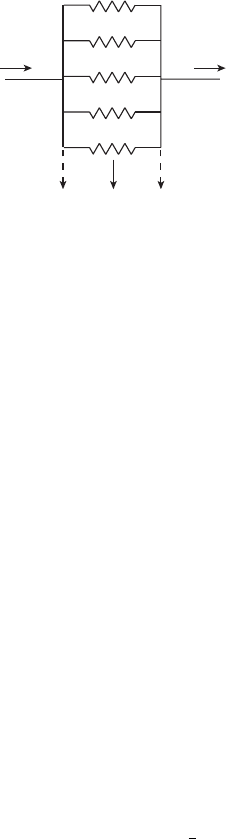
The flow from the manifold and through the fuel cells is analogous to current flow
through a parallel resistance network, as illustrated in Figure 6.50. If one of the individual
cells has a slightly different pressure drop due to liquid accumulation or DM sag, the flow
c06 JWPR067-Mench January 26, 2008 20:1 Char Count=
338 Polymer Electrolyte Fuel Cells
Inlet manifold flow exit manifold flow
R
1
R
5
R
3
R
4
R
2
etc.
Figure 6.50 Flow from manifold into fuel cell stack plates is analogous to resistor in parallel net-
work. Minute variations in the pressure drop through any of the plates can result in flow redistribution
and cause severe damage.
into that cell will be reduced, possibly below the minimum required flow to produce the
stack current. In this case, that cell voltage will go to zero or even a negative value (voltage
reversal), reducing the efficiency of the stack and increasing the heat release.
Voltage reversal can lead to rapid cell degradation from excessive heat release and unde-
sired side reactions that take place to produce the necessary stack current. While impossible
galvanically for a single cell, an individual fuel cell in a stack can undergo voltage reversal
by using available power from the properly functioning cells to drive undesired electrolytic
reactions. Voltage reversal can occur when the conditions are such that it is not possible to
generate the stack current in a galvanic mode. Since the individual cells are generally in
series electrically, each cell must carry the same current, but the voltage in each cell can
be different. As long as the total stack voltage is greater than zero, individual cells in
the stack can be powered electrolytically by the rest of the stack to produce the required
current through alternative electrochemical reactions. Essentially, if the current cannot be
produced by the available galvanic cell voltage, the cell will be powered by the other cells
in electrolytic mode to a negative voltage where the current is produced by some other
electrochemical reaction. In some cases, the alternative reaction can be benign, such as
water electrolysis. In other cases, the reaction is irreversible and permanently degrades the
electrode. For example, if the anode flow is blocked, the anode potential will rise, reducing
the fuel cell voltage. The first significant electrolytic reaction that will occur at the anode
to produce current is water electrolysis:
H
2
O → 2H
+
+ 2e
−
+
1
2
O
2
(6.39)
This reaction is benign and will not cause irreversible damage in small quantities. If this
reaction cannot generate enough current, the anode potential will continue to rise, eventually
driving the anode to oxidize the carbon in the electrode support at sufficiently negative cell
voltages:
C + 2H
2
O → CO
2(g)
+ 4H
+
+ 4e
−
(6.40)
Normally, this reaction occurs so slowly at PEFC temperatures and potentials that it is not a
concern. However, under a reversal situation the cell voltage can become negative enough
to accelerate this reaction to appreciable levels.
c06 JWPR067-Mench January 26, 2008 20:1 Char Count=
6.4 Direct Alcohol Polymer Electrolyte Cells 339
If there is oxidant starvation, the anode oxidation continues, but due to the absence of
oxygen, the cathode potential is decreased to around 0–100 mV, where protons are reduced.
This is called a hydrogen pump and is benign:
2H
+
+ 2e
−
→ H
2
(6.41)
In general, voltage reversal must be avoided during operation to prevent accelerated degra-
dation.
6.4 DIRECT ALCOHOL POLYMER ELECTROLYTE
CELLS
Hydrogen is a high-efficiency fuel for fuel cells but has several technical drawbacks which
engender an alternative fuel in certain applications.
Ĺ Storage and transportation of hydrogen are not yet established or simple.
Ĺ Storage of hydrogen is bulky in the gas phase, heavy stored in solid-phase hydrides,
and cryogeninc and expensive in the liquid phase.
Ĺ Hydrogen is highly flammable and has an invisible flame. Broad mixes of hydrogen
in air between 4 and 74% hydrogen are flammable.
Ĺ The H
2
PEFC requires ancillary components such as humidifiers and coolant recir-
culators that can be larger than the fuel cell stack itself.
Chapter 8 discusses the hydrogen storage, generation, and delivery in greater detail. For
now, we can identify two major applications where the use of stored hydrogen fuel may
not be the best solution:
1. Portable applications, where system compactness and not efficiency is the most
valuable design parameter.
2. Stationary and distributed power applications, where delivery of hydrogen is not
readily available, but natural gas is.
For stationary applications, the most common solution is to use a stream of reformed
hydrogen as fuel. In fuel reformation, a hydrogen carrying liquid fuel such as methane
or ethanol is partially oxidized into a hydrogen-rich mixture including carbon dioxide,
water vapor, and other species. If operating on reformed gas, the PEFC is still technically
a hydrogen fuel cell.
For portable applications, a liquid alcohol solution can be directly used as fuel, and the
reformation process occurs internally at the anode. The ultimate charge transfer at the anode
and the cathode for the DAFC is the same as the hydrogen fuel cell. That is, protons and
electrons are produced at the anode to generate current, and oxygen is reduced at the cathode.
Unlike hydrogen oxidation, there are many intermediate reactions which occur in the DAFC
anode to break the bonds of the original fuel until oxidation and charge transfer occur. This
logically means the electrochemical efficiency of the DAFC is lower than a hydrogen PEFC,
since the electrochemical oxidation reaction is more complex than hydrogen oxidation, and
will therefore have comparatively higher activation losses. However, since the density of
the liquid is much greater than gas-phase hydrogen, fuel storage is much more compact
that compressed hydrogen. Additionally, with the use of liquid fuel, other ancillary systems