Menon E.S. Liquid Pipeline Hydraulics
Подождите немного. Документ загружается.

Pump Analysis 143
lift and to a lesser extent for pipe friction. In the latter case, if two pumps
are used in series and one shuts down, the remaining pump alone will only
be able to provide half the head and therefore will not be able to provide
the necessary head for the static lift at any flow rate. If the pumps were
configured in parallel, then shutting down one pump will still allow the
other pump to provide the necessary head for the static lift at half the
previous flow rate. Thus parallel pumps are generally used when elevation
differences are considerable. Series pumps are used where pipeline
elevations are not significantly high.
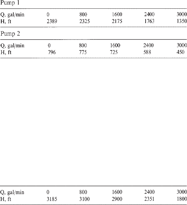
Example Problem 7.4
One large pump and one small pump are operated in series. The H-Q
characteristics of the pumps are defined as follows:
(a) Calculate the combined performance of pump 1 and pump 2 in
series configuration.
(b) What changes (trimming impellers) must be made to either pump
to satisfy the requirement of 2000 ft of head at 2400 gal/min when
operated in series?
(c) Can these pumps be configured to operate in parallel?
Solution
(a) Pumps in series have the same flow through each pump and the heads
are additive. We can therefore generate the total head produced in series
configuration by adding the head of each pump for each flow rate given as
follows:
Combined performance of pump 1 and pump 2 in series:
Copyright © 2004 by Marcel Dekker, Inc.
Chapter 7144
(b) It can be seen from the above combined performance that the head
generated at 2400 gal/min is 2351 ft. Since the design requirement is 2000
ft at this flow rate, it is clear that the head needs to be reduced by trimming
one of the pump impellers to produce the necessary total head. We will
proceed as follows.
Let us assume that the smaller pump will not be modified and the
impeller of the larger pump (pump 1) will be trimmed to produce the
necessary head.
Modified head required of pump 1=2000-588=1412 ft.
Pump 1 produces 1763 ft of head at 2400 gal/min. In order to reduce this
head to 1412 ft, we must trim the impeller by approximately
(1412/1763)
1/2
=0.8949 or 89.5%
based on Affinity Laws. This is only approximate and we need to generate
a new H-Q curve for the trimmed pump 1 so we can verify that the desired
head will be generated at 2000 gal/min. Using the method in Example
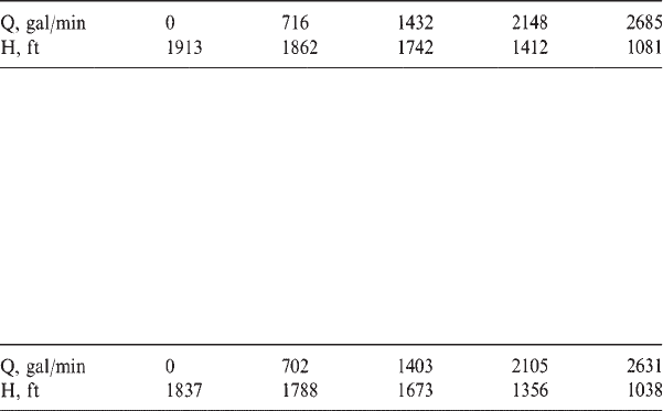
Problem 7.2 we can generate a new H-Q curve for a trim of 89.5%:
Flow multiplier=0.8949
Head multiplier=(0.8949)
2
=0.8008
Pump 1 trimmed to 89.5% of present impeller diameter:
It can be seen from above trimmed pump performance that the desired
head of 1412 ft will be achieved at a flow rate of 2148 gal/min. Therefore,
at the lower flow rate of 2000 gal/min, we can estimate by interpolation
that the head would be higher than 1412 ft. Hence, slightly more trimming
would be required to achieve the design point of 1412 ft at 2000 gal/min.
By trial and error we arrive at a pump trim of 87.7% and the resulting
pump performance for pump 1 at 87.7% trim is as follows:
Pump 1 trimmed to 87.7% of present impeller diameter:
By plotting this curve, we can verify that the required head of 1412 ft
will be achieved at 2000 gal/min.
Copyright © 2004 by Marcel Dekker, Inc.
Pump Analysis 145
(c) To operate satisfactorily in a parallel configuration, the two pumps
must have a common range of heads so that at each common head, the
corresponding flow rates can be added to determine the combined
performance. Pump 1 and pump 2 are mismatched for parallel operation.
Therefore, they cannot be operated in parallel.
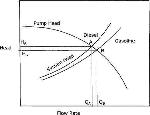
7.10 Pump Head Curve Versus System Head Curve
In Chapter 5 we discussed the development of pipeline system head
curves. In this section we will see how the system head curve together with
the pump head curve can predict the operating point (flow rate Q—head H)
on the pump curve.
Since the system head curve for the pipeline is a graphic representation
of the pressure required to pump a product through the pipeline at various
flow rates (increasing pressure with increasing flow rate) and the pump H-
Q curve shows the pump head available at various flow rates, when the
head requirements of the pipeline match the available pump head we have
a point of intersection of the system head curve with the pump head curve
as shown in Figure 7.12. This is the operating point for this pipe-pump
combination.
The point of intersection of the pump head curve and the system head
curve for diesel (point A) indicates the operating point for this pipeline
Figure 7.12 Pump head and system head curves.
Copyright © 2004 by Marcel Dekker, Inc.
Chapter 7146
with diesel. Similarly, if gasoline were pumped through this pipeline, the
corresponding operating point (point B) is as shown in Figure 7.12.
Therefore, with 100% diesel in the pipeline, the flow rate would be Q
A
and
the corresponding pump head would be H
A
as shown. Similarly, with
100% gasoline in the pipeline, the flow rate would be Q
B
and the
corresponding pump head would be H
B
as shown in Figure 7.12. When
batching the two products, a certain proportion of the pipeline will be filled
with diesel and the rest will be filled with gasoline. The flow rate will then
be at some point between Q
A
and Q
B
, since a new system head curve
located between the diesel curve and the gasoline curve will dictate the
operating point.
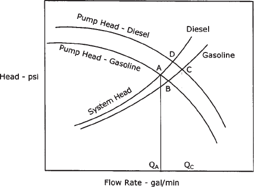
If we had plotted the system head curve in psi instead of ft of liquid
head, the Y-axis will be the pressure required (psi). The pump head curve
also needs to be converted to psi versus flow rate by using Equation (3.7):
Psi=Head×Sg/2.31
Therefore, using the same pump we will have two separate H-Q curves for
diesel and gasoline, due to different specific gravities. Such a situation is
shown in Figure 7.13. Even though the pump develops the same head (in ft)
with diesel or gasoline (or water), the pressure generated in psi will be
different, and hence the two separate H-Q curves, as indicated in Figure 7.13.
In a batched pipeline, the operating point moves from D to A, A to B, B
to C, and C to D as shown in Figure 7.13. We start off with 100% diesel in
Figure 7.13 Pump and system curve: batching.
Copyright © 2004 by Marcel Dekker, Inc.
Pump Analysis 147
the pipeline and the pump. This is point D in the figure. When gasoline
enters the pump, with diesel in the pipeline, the operating point moves
from D to A. Then, as the gasoline batch enters the pipeline, the system
head curve moves to the right until it reaches point B representing the
operating point with 100% gasoline in the pipeline and gasoline in the
pump. As diesel reaches the pump and the line is still full of gasoline, the
operating point moves to C, where we have diesel in the pump and the
pipeline filled with gasoline. Finally, as the diesel batch enters the pipeline,
the operating point moves towards D. At D we have completed the cycle
and both the pump and the pipeline are filled with diesel. Thus it is seen
that in a batched operation the flow rates vary between Q
A
and Q
C
as in
Figure 7.13.
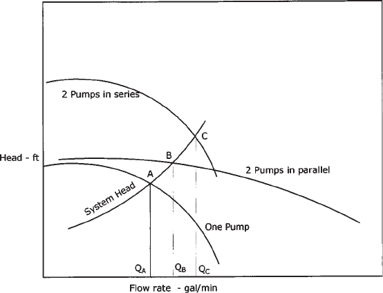
7.11 Multiple Pumps Versus System Head Curve
When two or more pumps are operated in parallel on a pipeline system, we
saw how the pump head curves added the flow rates at the same head to
create the combined pump performance curve. Similarly, with series
pumps, the heads are added up for the same flow rate resulting in the
combined pump head curve.
Figure 7.14 illustrates the pipeline system head curve superimposed on
the pump head curves to show the operating point with one pump, two
Figure 7.14 Multiple pumps and system head curve.
Copyright © 2004 by Marcel Dekker, Inc.
Chapter 7148
pumps in series and the same two pumps in parallel configurations. The
operating points are shown as A, C, and B with flow rates of Q
A
, Q
C
, and
Q
B
, respectively.
In certain pipeline systems, depending upon the flow requirements, we
may be able to obtain higher throughput by switching from a series pump
configuration to a parallel pump configuration. From Figure 7.14 it can be
seen that a steep system head curve would favor pumps in series, while a
relatively flat system head curve is associated with the operation of parallel
pumps.
7.12 NPSH Required Versus NPSH Available
As the pressure on the suction side of a pump is reduced to a value below
the vapor pressure of the liquid being pumped, flashing can occur. The
liquid vaporizes and the pump is starved of liquid. At this point the pump
is said to cavitate due to insufficient liquid volume and pressure. The vapor
can damage the pump impeller, further reducing its ability to pump. To
avoid vaporization of liquid, we must provide adequate positive pressure at
the pump suction that is greater than the liquid vapor pressure.
NPSH for a centrifugal pump is defined as the net positive suction head
required at the pump impeller suction to prevent pump cavitation at any
flow rate. Cavitation will damage the pump impeller and render it useless.
NPSH represents the resultant positive pressure at the pump suction. In
this section, we will analyze a piping configuration from a storage tank to
a pump suction, to calculate the available NPSH and compare it with the
NPSH required by the pump vendor’s performance curve. The NPSH
available will be calculated by taking into account any positive tank head,
including atmospheric pressure, and subtracting the pressure drop due to
friction in the suction piping and the liquid vapor pressure at the pumping
temperature. The resulting value of NPSH for this piping configuration
will represent the net pressure of the liquid at pump suction, above its
vapor pressure. The value calculated must be more than the NPSH
specified by the pump vendor at the particular flow rate.
Before we calculate the NPSH available in a typical pump-piping
configuration, let us analyze the piping geometry associated with a pump
taking suction from a tank and delivering liquid to another tank as shown
in Figure 7.15.
The vertical distance from the liquid level on the suction side of the
pump center line is defined as the static suction head. More correctly, it is
the static suction lift (H
S
) when the center line of the pump is above that of
the liquid supply level as depicted in Figure 7.15. If the liquid supply level
is higher than the pump center line, it is called the static suction head on
Copyright © 2004 by Marcel Dekker, Inc.
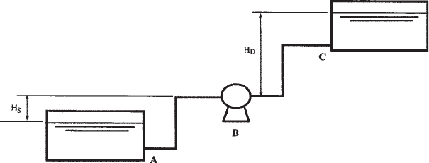
Pump Analysis 149
the pump. Similarly, the vertical distance from the pump center line to the
liquid level on the delivery side is called the static discharge head (H
D
) as
shown in Figure 7.15.
The total static head on a pump is defined as the sum of the static
suction head and the static discharge head. It represents the vertical
distance between the liquid supply level and the liquid discharge level. The
static suction head, static discharge head, and the total static head on a
pump are all measured in feet of liquid, or meters of liquid in the SI
system.
The friction head, measured in feet of liquid pumped, represents the
pressure drop due to friction in both suction and discharge piping. It
represents the pressure required to overcome the frictional resistance of all
piping, fittings, and valves on the suction side and discharge side of the
pump as shown in Figure 7.15. Reviewing the piping system shown in
Figure 7.15, it is seen that there are three sections of straight piping and
two pipe elbows on the suction side between the liquid supply (A) and the
center line of the pump. In addition, there would be at least two valves, one
at the tank and the other at the inlet to the pump suction. An entrance loss
will be added to account for the pipe entrance at the tank.
Similarly, on the discharge side of the pump between the center line of
the pump (B) and the tank delivery point (C) there are three straight
sections of pipe and two pipe elbows along with two valves. On the
discharge of the pump there would also be a check valve to prevent reverse
flow through the pump. An exit loss at the tank entry will also be added to
account for the delivery pipe.
On the suction side of the pump, the available suction head H
S
will be
reduced by the friction loss in the suction piping. This net suction head on
the pump will be the available suction head at the pump center line.
Figure 7.15 Centrifugal pump: suction and discharge heads.
Copyright © 2004 by Marcel Dekker, Inc.
Chapter 7150
On the discharge side the discharge head H
D
will be increased by the
friction loss in the discharge piping. This is the net discharge head on the
pump.
Mathematically,
Suction head=H
S
-H
fs
(7.10)
Discharge head=H
D
+H
fd
(7.11)
where
H
fs
=Friction loss in suction piping
H
fd
=Friction loss in discharge piping
If the suction piping is such that there is a suction lift (instead of suction
head) the value of H
S
in Equation (7.10) will be negative. Thus a 20 ft
static suction lift combined with a suction piping loss of 2 ft will actually
result in an overall suction lift of 22 ft. The discharge head, on the other
hand, will be the sum of the discharge head and friction loss in the
discharge piping. Assuming a 30 ft discharge head and 5 ft friction loss,
the total discharge head will be 30+5=35 ft. In this example, the total head
of the pump is 22+ 35=57 ft.
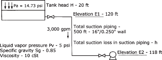
Example Problem 7.5
A centrifugal pump is used to pump a liquid from a storage tank through
500 ft of suction piping as shown in Figure 7.16.
(a) Calculate the NPSH available at a flow rate of 3000 gal/min.
(b) The pump vendor’s data indicate the NPSH required to be 35 ft at
3000 gal/min and 60 ft at 4000 gal/min. Can this piping system
handle the higher flow rate without the pump cavitating?
(c) If cavitation is a problem in (b) above, what changes must be made
to the piping system to prevent pump cavitation at 4000 gal/min?
Figure 7.16 NPSH calculation.
Copyright © 2004 by Marcel Dekker, Inc.
Pump Analysis 151
Solution
(a) NPSH available in ft of liquid head:
(P
a
-P
v
)(2.31/Sg)+H+E1-E2-h (7.12)
where
P
a
=Atmospheric pressure, psi
P
v
=Liquid vapor pressure at the flowing temperature, psi
Sg=Liquid specific gravity
H=Tank head, ft
E1=Elevation of tank bottom, ft
E2=Elevation of pump suction, ft
h=Friction loss in suction piping, ft
All terms in Equation (7.12) are known except for the suction piping
loss h.
The suction piping loss h is calculated at the given flow rate of 3000
gal/min, considering 500 ft of 16 in. piping, pipe fitting, valves, etc., in the
given piping configuration. The total equivalent length of 16 in. pipe,
including two gate valves and two elbows, is:
Equivalent length of 16 in. pipe=500 ft+2×8×(16/12)
+2×30×(16/12)
using an L/D ratio of 8 for the gate valves and 30 for each 90° elbow (from
Table A.10, Appendix A). Therefore
L
e
=500+21.33+80=601.33 ft
Using the Colebrook-White equation and assuming a pipe roughness of
0.002 in., we calculate the pressure drop at 3000 gal/min as
P
m
=12.77 psi/mile
Therefore
h=12.77×2.31×601.33/(0.85×5280)=3.95 ft
Substituting h and other values in Equation (7.12) we get
NPSH=(14.73-5)×2.31/0.85+20+120-118-3.95
=44.49 ft available
(b) At 4000 gal/min
Pressure loss P
m
=21.43 psi/mile
Copyright © 2004 by Marcel Dekker, Inc.
Chapter 7152
and
h=6.63 ft
Available NPSH at 4000 gal/min=44.49+3.95-6.63=41.81 ft
Since available NPSH is less than the NPSH of 60 ft required by the pump
vendor, the pump will cavitate.
(c) The extra head required to prevent cavitation=60-41.81=18 ft.
One solution is to locate the pump suction at an additional 18 ft or more
below the tank. Another solution would be to provide a small vertical can
pump that can serve as booster for the main pump. This pump will provide
the additional head required to prevent cavitation.
7.13 Summary
We have discussed centrifugal pumps and their performance
characteristics as they apply to liquid pipeline hydraulics. Other types of
pumps such as PD pumps used in injecting liquid into flowing pipelines
were briefly covered. Pump performance at different impeller sizes and
speeds, based on Affinity Laws, were discussed and illustrated using
examples. Trimming impellers or reducing speeds (VSD pumps) to match
system pressure requirements was also explored.
The important parameter NPSH was introduced and methods of
calculations for typical pump configurations were shown. We also
discussed how the water performance curves provided by a pump
vendor must be corrected, using the Hydraulic Institute chart, when
pumping high-viscosity liquids. The performance of two or more
pumps in series or parallel configuration was analyzed using an
example. In addition, we demonstrated how the operating point can be
determined by the point of intersection of a system head curve and the
pump head curve. In batched pipelines the variation of operating point
on a pump curve using the system head curves for different products
was illustrated.
7.14 Problems
7.14.1 Two pumps are used in series configuration. Pump A develops
1000 ft head at 2200 gal/min and pump B generates 850 ft
head at the same flow rate. At the design flow rate of 2200 gal/
min, the application requires a head of 1700 ft. The current
impeller sizes in both pump are 10 in. diameter.
Copyright © 2004 by Marcel Dekker, Inc.