Middleton W.M. (ed.) Reference Data for Engineers: Radio, Electronics, Computer and Communications
Подождите немного. Документ загружается.

14-12
REFERENCE
DATA
FOR ENGINEERS
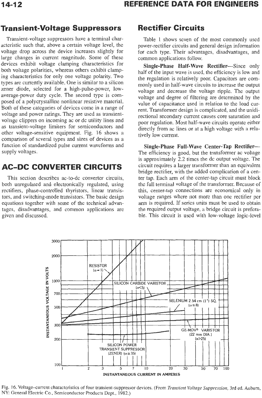
Transient-Voltage Suppressors
Transient-voltage suppressors have a terminal char-
acteristic such that, above a certain voltage level, the
voltage drop across the device increases slightly for
large changes
in
current magnitude. Some of these
devices exhibit voltage clamping characteristics for
both voltage polarities, whereas others exhibit clamp-
ing characteristics for only one voltage polarity. Two
types are currently available. One is similar
to
a silicon
zener diode, selected for a high-pulse-power, low-
average-power duty cycle. The second type is com-
posed of a polycrystalline nonlinear resistive material.
Both of these categories of devices come in a range of
voltage and power ratings. They are used as transient-
voltage clippers on incoming ac or dc utility lines and
as transient-voltage limiters for semiconductors and
other voltage-sensitive equipment. Fig.
16
shows a
comparison of several types and sizes of devices as a
function of standardized pulse current waveforms and
supply voltages.
AC-DC CONVERTER CIRCUITS
This section describes ac-to-dc converter circuits,
both unregulated and electronically regulated, using
rectifiers, phase-controlled thyristors, linear transis-
tors, and switching-mode transistors. The basic design
equations together with some of the technical advan-
tages, disadvantages, and common applications are
given and discussed.
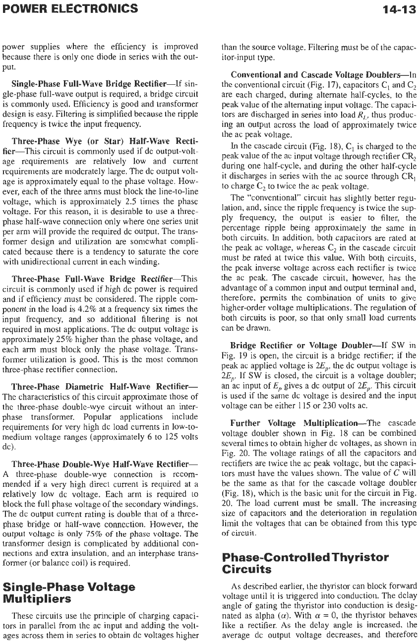
Rectifier Circuits
Table
1
shows seven of the most commonly used
power-rectifier circuits and general design information
for each type. Their advantages, disadvantages, and
common applications follow.
Single-phase Half-Wave Rectifier-Since only
half of the input wave is used, the efficiency is low and
the regulation is relatively poor. Capacitors
are
com-
monly used in half-wave circuits to increase the output
voltage and decrease the voltage ripple. The output
voltage and degree of filtering are determined by the
value of capacitance used in relation
to
the
load cur-
rent. Transformer design is complicated, and the unidi-
rectional secondary current causes core saturation and
poor regulation. Most half-wave circuits operate either
directly from ac lines or at a high voltage with a rela-
tively low current.
Single-phase Full-Wave Center-Tap Rectifier-
The efficiency is good, but the transformer ac voltage
is approximately
2.2
times the dc output voltage. The
circuit requires
a
larger transformer than an equivalent
bridge rectifier, with the added complication of a cen-
ter tap. Each
arm
of the center-tap circuit must block
the full terminal voltage of the transformer. Because of
this, center-tap connections are economical only in
voltage ranges where not more than one rectifier per
arm
is required. If series units must be used
to
obtain
the required output voltage, a bridge circuit is prefera-
ble. This circuit is used with low-voltage logic-level
INSTANTANEOUS CURRENT IN AMPERES
Fig.
16.
Voltage-current
characteristics
of
four transient-suppressor devices.
(From
Transient
Voltage
Suppression,
3rd ed.
Auburn,
NY.
General
Electric Co., Semiconductor Products
Dept.,
1982.)
14-1
3
power supplies where the efficiency is improved
because there is only one diode in series with the out-
put.
Single-phase Full-Wave Bridge Rectifier-If sin-
gle-phase full-wave output is required, a bridge circuit
is commonly used. Efficiency is good and transformer
design is easy. Filtering is simplified because the ripple
frequency is twice the input frequency.
Three-phase Wye (or Star) Half-Wave Recti-
fier-This circuit is commonly used if dc output-volt-
age requirements are relatively low and current
requirements
are
moderately large. The dc output volt-
age is approximately equal to the phase voltage. How-
ever, each of the three
arms
must block the line-to-line
voltage, which is approximately 2.5 times the phase
voltage. For this reason, it is desirable to use a three-
phase half-wave connection only where one series unit
per arm will provide the required dc output. The trans-
former design and utilization are somewhat compli-
cated because there is a tendency to saturate the core
with unidirectional current in each winding.
Three-phase Full-Wave Bridge Rectifier-This
circuit is commonly used if high dc power is required
and if efficiency must be considered. The ripple com-
ponent
in
the load is 4.2% at a frequency six times the
input frequency, and
so
additional filtering is not
required
in
most applications. The dc output voltage is
approximately 25% higher than the phase voltage, and
each
arm
must block only the phase voltage. Trans-
former utilization is good. This is the most common
three-phase rectifier connection.
Three-phase Diametric Half-Wave Rectifier-
The characteristics of this circuit approximate those of
the three-phase double-wye circuit without an inter-
phase transformer. Popular applications include
requirements for very high dc load currents in low-to-
medium voltage ranges (approximately
6
to 125 volts
dc).
Three-phase Double-Wye Half-Wave Rectifier-
A
three-phase double-wye connection is recom-
mended if a very high direct current is required at a
relatively low dc voltage. Each
arm
is required to
block the full phase voltage of the secondary windings.
The dc output current rating is double that of a three-
phase bridge
or
half-wave connection. However, the
output voltage
is
only
75%
of the phase voltage. The
transformer design is complicated by additional con-
nections and extra insulation, and an interphase trans-
former (or balance coil) is required.
Single-phase Voltage
Multipliers
These circuits use the principle of charging capaci-
tors in parallel from the ac input and adding the volt-
ages across them in series to obtain dc voltages higher
than the source voltage. Filtering must be of the capac-
itor-input type.
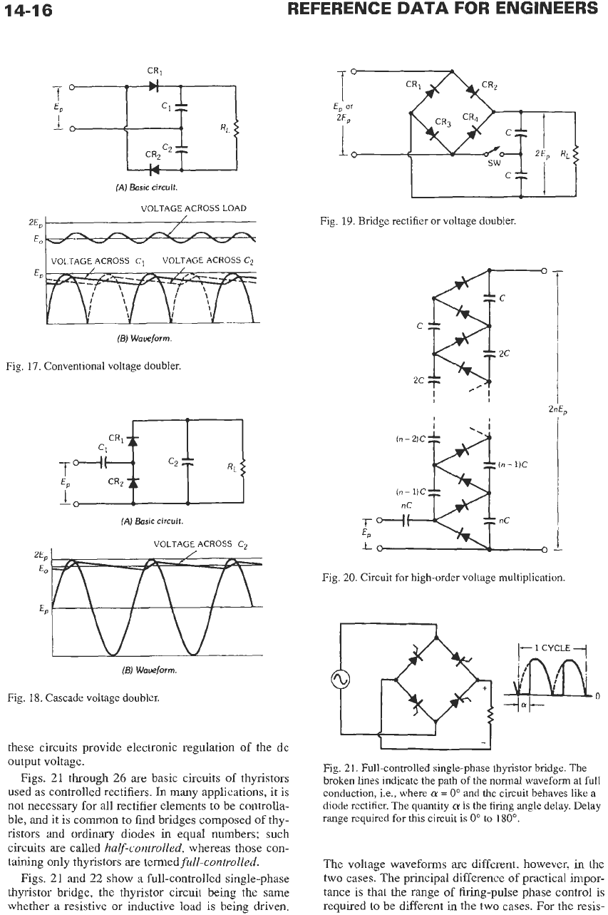
Conventional and Cascade Voltage Doubler-In
the conventional circuit (Fig.
17),
capacitors
C,
and
C,
are each charged, during alternate half-cycles, to the
peak value of the alternating input voltage. The capaci-
tors are discharged in series into load
RL,
thus produc-
ing an output across the load of approximately twice
the ac peak voltage.
In
the cascade circuit (Fig. 18),
C,
is charged to the
peak value
of
the ac input voltage through rectifier
CR,
during one half-cycle, and during the other half-cycle
it discharges
in
series with the ac source through
CR,
to charge
C,
to twice the ac peak voltage.
The "conventional" circuit has slightly better regu-
lation, and, since the ripple frequency is twice the sup-
ply frequency, the output is easier to filter, the
percentage ripple being approximately the same
in
both circuits.
In
addition, both capacitors are rated at
the peak ac voltage, whereas
C,
in
the cascade circuit
must
be rated at twice
this
value. With both circuits,
the peak inverse voltage across each rectifier
is
twice
the ac peak. The cascade circuit, however, has the
advantage of a common input and output terminal and,
therefore, permits the combination of units to give
higher-order voltage multiplications. The regulation
of
both circuits is poor,
so
that only small load currents
can be drawn.
Bridge Rectifier or Voltage Doubler-If SW in
Fig.
19
is open, the circuit is a bridge rectifier; if the
peak ac applied voltage is 2Ep, the dc output voltage is
2Ep. If SW is closed, the circuit is a voltage doubler;
an
ac input of
Ep
gives a dc output of 2Ep. This circuit
is used if the same dc voltage is desired and the input
voltage can be either 115 or 230 volts ac.
Further Voltage Multiplication-The cascade
voltage doubler shown in Fig. 18 can be combined
several times to obtain higher dc voltages, as shown in
Fig. 20. The voltage ratings of all the capacitors and
rectifiers are twice the ac peak voltage, but the capaci-
tors must have the values shown. The value of
C
will
be the same as that for the cascade voltage doubler
(Fig.
lS),
which is the basic unit for the circuit
in
Fig.
20.
The load current must be small. The increasing
size of capacitors and
the
deterioration
in
regulation
limit the voltages that can be obtained from this type
of
circuit.
Phase-Controlled Thyristor
Circuits
As
described earlier, the thyristor can block forward
voltage until it is triggered into conduction. The delay
angle
of
gating the thyristor into conduction is desig-
nated as alpha
(a).
With
a
=
0,
the thyristor behaves
like a rectifier.
As
the delay angle is increased, the
average dc output voltage decreases, and therefore
14-1
4
REFERENCE
DATA
FOR ENGINEERS
TABLE
1.
RECTIFIER
Type of Circuit-,
Primary+
Secondary4
One Cycle Wave of Rectifier
Output Voltage
(No Overlap)
Single-phase Single-phase Single-phase Three-phase Star
Half-Wave Center Tap Bridge (Wye)
Number of rectifier elements
Rms dc volts output
Peak dc volts output
Peak reverse volts per
rectifier element
Average dc output current
Average dc output current
per rectifier element
Rms current per rectifier
element:
Resistive load
Inductive load
rectifier element:
Resistive load
Inductive load
Ratio of peak
to
average
current per element:
Resistive load
Inductive load
%
Ripple (rms of ripple/
average output voltage)
Ripple Frequency
Peak current per
Transformer secondary
rms
volts per leg
Transformer secondary
rms
volts line-to-line
Secondary line current
Transformer secondary
Transformer primary
Transformer primary
Average of primary and
Primary line current
volt-amperes
rms
amperes per leg
volt-amperes
secondary volt-amperes
Line power factor
1
1.57
3.14
3.14
1.41
1.41
1
.oo
1
.oo
1.57
-
3.14
-
3.14
-
121%
1
Resistive Load
2.22
2.22
1.57
3.49
1.21
2.69
3.09
1.21
-
2 4 3
1.11 1.11 1.02
1.57 1.57 1.21
3.14 1.57 2.09
2.82 1.41 2.45
1.41 1.41 1.41
1
.oo
1
.oo
1
.oo
0.500
0.500
0.333
0.785 0.785 0.587
0.707 0.707 0.578
1.57
1.57
1.21
1
.oo
1
.oo
1
.oo
3.14 3.14 3.63
2.00 2.00 3.00
48% 48% 18.3%
2 2 3
Inductive Load or Large Choke Input Filter
1.11 1.11 0.855
(to center tap) (total)
(to
neutral)
2.22
1.11
1.48
0.707 1
.oo
0.578
1.57 1.11 1.48
1
.oo
1
.oo
0.471
1.11
1.11
1.21
1.34 1.11 1.35
1
.oo
1
.oo
0.817
0.900
0.900
0.826
*
The
data assume zero forward
drop
and zero reverse current in rectifiers and no alternating-current line or source reactance.
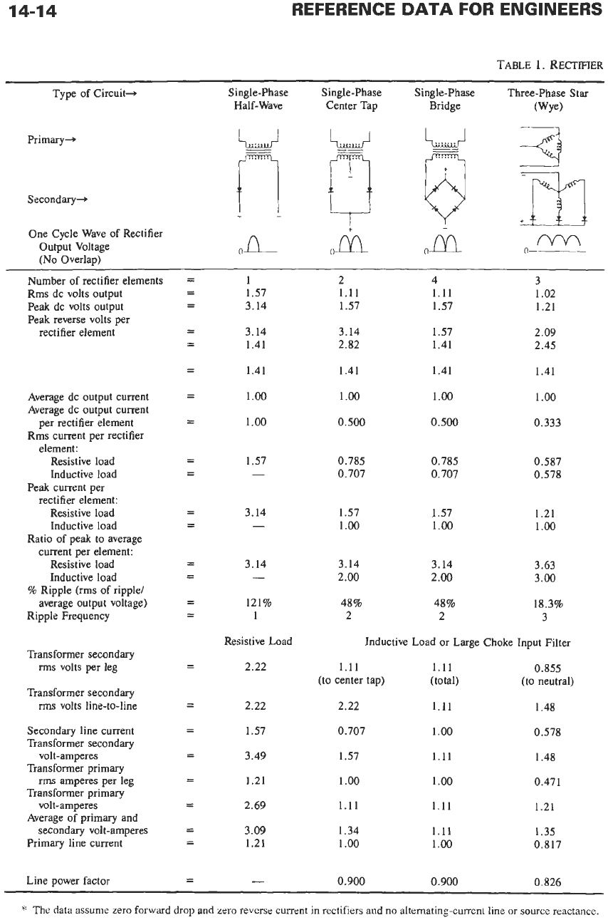
14-1
5
CIRCUIT
CHART
*
Three-phase Bridge Six-Phase Star Three-phase
Double
Wye
(Three-phase Diametric) With Interphase Transformer
Ih
To
Determine Actual
Value of Parameter in
rrTyyy',
rrTyyy',
Any Column, Multiply
0
0
Factor Shown
by
Value
of
6
1
.oo
1.05
1.05
2.45
1.41
6
1
.oo
1.05
2.09
2.83
1.41
6
1
.oo
1.05
2.42
2.83
I
.41
(diametric)
1
.oo
0.167
X
Average dc voltage output
X
Average dc voltage output
X
Average dc voltage output
X
Rms
secondary volts per
transformer leg
X
Rms
secondary volts
line-to-line
X
Average dc output current
X
Average dc output current
1
.oo
0.333
1
.oo
0.167
0.579
0.578
0.409 0.293
0.408 0.289
X
Average dc output current
X
Average dc output current
1.05
1
.oo
1.05
0.525
1
.oo
0.500
X
Average dc output current
X
Average dc output current
3.15
3.00
6.30
6.00
3.15
3.00
4.2%
6
4.2%
6
4.2%
6
Line frequency,
f
X
Inductive Load
or
Large Choke Input Filter
0.428
0.740
(to neutral) (to neutral)
0.855
(to neutral)
1.71
(max-no load)
0.289
Average dc voltage output
X
0.740
0.816
1.48
0.408
(max)
Average dc voltage output
Average
dc
output current
Dc
watts output
Average dc output current
Dc
watts output
Dc
watts output
(Avg. load current
X
sec.
leg
voltage)/primary
line voltage
X
X
I
.05
1.81
0.816 0.577
1.05
1.28
1.48
0.408
1.05
1.26
0.707
X
X
X
1.05
I
.41
1.55
0.817
X
X
0
955
0.955
0.955
14-16
2%
Eo
REFERENCE
DATA
FOR
ENGINEERS
-
/
------4-n--x
VOLTAGE ACROSS
C1
VOLTAGE ACROSS
Cs
(E)
Waveform.
Fig.
17.
Conventional voltage doubler.
(A)
Basic circuit.
VOLTAGE
ACROSS
C2
(E)
Waveform
Fig.
18.
Cascade voltage doubler.
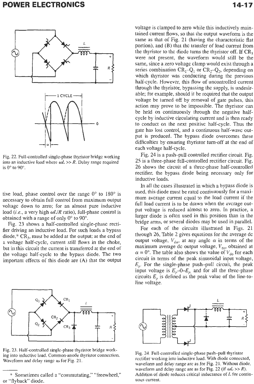
these circuits provide electronic regulation of
the
dc
output voltage.
Figs. 21 through 26
are
basic circuits of thyristors
used
as
controlled rectifiers.
In
many applications, it is
not necessary for all rectifier elements
to
be controlla-
ble, and it is common to find bridges composed of thy-
ristors and ordinary diodes
in
equal numbers; such
circuits are called
halfcontrolled,
whereas those con-
taining only thyristors
are
termed
full-controlled.
Figs.
21
and 22 show a full-controlled single-phase
thyristor bridge, the thyristor circuit being the same
whether
a
resistive or inductive load is being driven.
Fig.
19.
Bridge rectifier or voltage doubler.
2"'E,
t
I
.I
Fig.
20.
Circuit for high-order voltage multiplication.
0
Fig.
21.
Full-controlled single-phase thyristor bridge. The
broken lines indicate the path of
the
normal waveform at
full
conduction, i.e., where
a
=
0"
and
the
circuit behaves
like
a
diode rectifier. The quantity
a
is
the
firing
angle delay. Delay
range required for this circuit is
0"
to
180".
The voltage waveforms are different, however,
in
the
two cases. The principal difference of practical impor-
tance is that the range of firing-pulse phase control is
required to be different
in
the two cases. For the resis-
POWER
ELECTRONICS
+
--
I-
<
-
14-1
7
I--
1
CYCLE
---I
0
Fig.
22.
Full-controlled single-phase thyristor bridge working
into
an inductive load where
wL
>>
R.
Delay range required
is
0"
to
90".
tive load, phase control over the range
0"
to
180"
is
necessary to obtain full control from maximum output
voltage down
to
zero; for an almost pure inductive
load
(ie.,
a very high
wLiR
ratio), full-phase control is
obtained with a range of only
0"
to
90".
Fig.
23
shows a half-controlled single-phase recti-
fier driving an inductive load. For such loads a bypass
diode," CR,, must be added at the output; at the end of
a voltage half-cycle, current still flows
in
the choke,
but in
this
circuit the current is transferred at the end of
the voltage half-cycle to the bypass diode. The two
important effects
of
this diode are
(A)
that the output
voltage is clamped to zero while this inductively main-
tained current flows,
so
that the output waveform is the
same as that of Fig.
21
(having the characteristic flat
portion), and
(B)
that the transfer of load current from
the thyristor to the diode turns the thyristor
off.
If CR,
were
not
present, the waveform would still be the
same, since a zero voltage clamp would exist through a
series combination CR,-Q, or CR,-Q,, depending
on
which thyristor was conducting during the previous
half-cycle. However,
this
flow
of
uncontrolled current
through the thyristor, bypassing the supply, is undesir-
able; for example, should it be required that
the
output
voltage be turned
off
by removal of gate pulses,
this
action may prove
to
be impossible. The thyristor can
be held
on
continuously through the negative half-
cycle by inductive circulating current and is then ready
to conduct
on
the next positive half-cycle.
Thus
the
gate has lost control, and a
continuous
half-wave out-
put is produced. The bypass diode overcomes these
difficulties by ensuring thyristor turn-off at the end of
each voltage half-cycle.
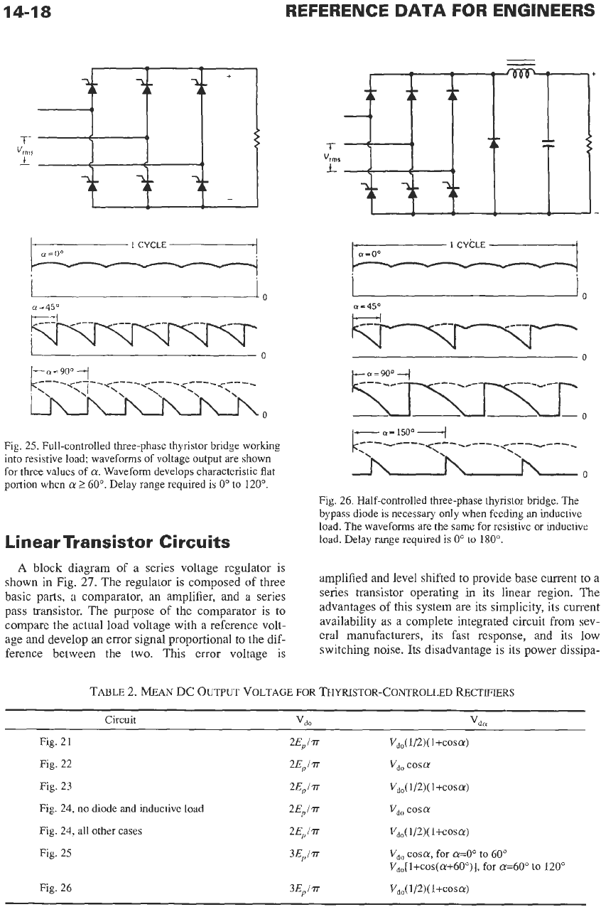
Fig.
24
is a push-pull controlled rectifier circuit. Fig.
25
is a three-phase full-controlled rectifier circuit. Fig.
26
shows the circuit of a three-phase half-controlled
rectifier, the bypass diode being necessary only for
inductive loads.
In
all the cases illustrated in which a bypass diode is
used, this diode must be rated continuously for a maxi-
mum average current equal to the load current if the
full load current is
to
be drawn when
the
average
out-
put voltage is reduced almost to zero.
In
practice, a
larger diode
is
often used in this position than in the
bridge
arms,
or several diodes may be used in parallel.
For each of the circuits illustrated in Figs.
21
through
26,
Table
2
gives equations for the average dc
output voltage,
V,,,
at any angle
a
in
terms of the
maximum average dc output voltage,
V,,,
obtained at
a
=
0".
The table also shows the value
of
V,,
for each
circuit in terms of the peak sinusoidal input voltage,
Ep.
For the single-phase push-pull circuit, the peak
input voltage is
E,,-O-Ep,
and for all the three-phase
circuits
Ep
is
defined as the peak value of the line-to-
line voltage.
L
Fig.
24.
Full-controlled single-phase push-pull thyristor
rectifier working into inductive load. With diode connected,
waveform and delay range
are
as for Fig.
21.
Without diode,
waveform and delay range
are
as for Fig.
22
(if
WL
>>
R).
Addition
of
diode reduces critical inductance
of
L
for contin-
uous current.
14-18
REFERENCE
DATA
FOR ENGINEERS
I
0
0
Fig. 25. Full-controlled three-phase thyristor bridge working
into resistive load; waveforms of voltage output are
shown
for three values of
a.
Waveform develops characteristic flat
portion
when
a
2
60". Delay range required is
0"
to
120".
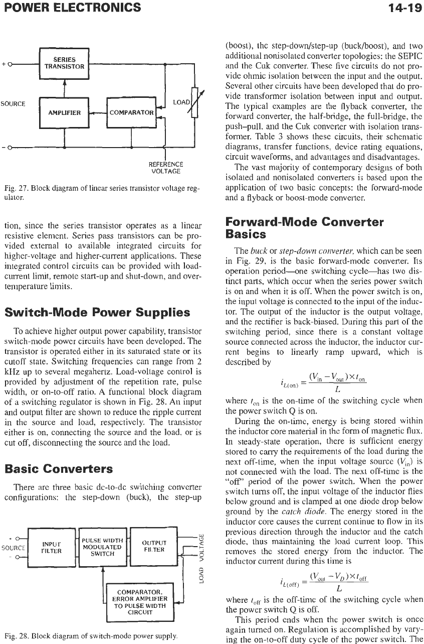
Linear Transistor Circuits
A
block diagram
of
a series voltage regulator is
shown
in
Fig.
27.
The regulator is composed of three
basic parts, a comparator, an amplifier, and a series
pass transistor. The purpose of the comparator is
to
compare the actual load voltage with a reference volt-
age and develop an error signal proportional to the dif-
ference between the two. This error voltage is
i
i
I
01
=
450
U
0
0
Fig.
26. Half-controlled three-phase thyristor bridge. The
bypass diode is necessary only when feeding an inductive
load. The waveforms are the
same
for
resistive
or
inductive
load. Delay range required
is
0"
to
180".
amplified and level shifted
to
provide base current to a
series transistor operating
in
its linear region. The
advantages
of
this system are its simplicity, its current
availability as a complete integrated circuit from sev-
eral manufacturers, its fast response, and its low
switching noise. Its disadvantage
is
its power dissipa-
TABLE
2.
MEAN
DC
OUTPUT
VOLTAGE FOR THYRISTOR-CONTROLLED
RECTIFIERS
Circuit
vdo
vda
Fig. 21
2EJa
Vd0(
1/2)(l+cosa)
Fig. 22
2EJr
v,,
cosa
Fig. 24, no diode and inductive load 2EJa
v,,
cosa
Fig. 24, all other cases 2EJr Vd0( 1/2)(1+cosa)
Fig. 23 2EJa vdo( 1/2)(1+cOsa)
Fig. 25
Fig. 26
14-19
SERIES
TRANSISTOR
+O
*
REFERENCE
VOLTAGE
Fig.
27.
Block
diagram
of
linear
series
transistor voltage
reg-
ulator.
tion, since the series transistor operates as a linear
resistive element. Series pass transistors can be pro-
vided external to available integrated circuits for
higher-voltage and higher-current applications. These
integrated control circuits can be provided with load-
current limit, remote start-up and shut-down, and over-
temperature limits.
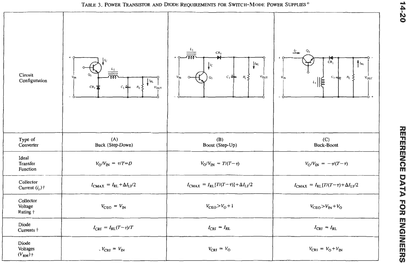
Switch-Mode Power Supplies
To achieve higher output power capability, transistor
switch-mode power circuits have been developed. The
transistor is operated either in its saturated state or its
cutoff state. Switching frequencies can range from
2
kHz up to several megahertz. Load-voltage control is
provided by adjustment of the repetition rate, pulse
width, or on-to-off ratio.
A
functional block diagram
of a switching regulator is shown in Fig.
28.
An
input
and output filter
are
shown to reduce the ripple current
in the source and load, respectively. The transistor
either is on, connecting the source and the load, or is
cut
off,
disconnecting the source and
the
load.
Basic Converters
There are three basic dc-to-dc switching converter
configurations: the step-down (buck), the step-up
COMPARATOR,
ERROR AMPLIFIER
TO
PULSE WIDTH
CIRCUIT
Fig.
28.
Block
diagram
of
switch-mode power
supply.
(boost), the step-dowdstep-up (buck/boost), and two
additional nonisolated converter topologies: the
SEPIC
and the
Cuk
converter. These five circuits do not pro-
vide ohmic isolation between the input and the output.
Several other circuits have been developed that do pro-
vide transformer isolation between input and output.
The typical examples are the flyback converter, the
forward converter, the half-bridge, the full-bridge, the
push-pull, and the
Cuk
converter with isolation trans-
former. Table
3
shows these circuits, their schematic
diagrams, transfer functions, device rating equations,
circuit waveforms, and advantages and disadvantages.
The vast majority of contemporary designs of both
isolated and nonisolated converters is based upon the
application of two basic concepts: the forward-mode
and a flyback or boost-mode converter.
Forward-Mode Converter
Basics
The
buck
or
step-down converter,
which can be seen
in
Fig.
29,
is the basic forward-mode converter. Its
operation period-one switching cycle-has two dis-
tinct parts, which occur when the series power switch
is on and when it
is
off.
When the power switch is
on,
the
input voltage is connected to the input of the induc-
tor. The output of the inductor is the output voltage,
and the rectifier
is
back-biased. During this part of the
switching period, since there is a constant voltage
source connected across the inductor, the inductor cur-
rent begins to linearly ramp upward, which is
described by
where
ton
is the on-time of the switching cycle when
the power switch
Q
is
on.
During the on-time, energy is being stored within
the inductor core material in the form of magnetic
flux.
In
steady-state operation, there is sufficient energy
stored to carry the requirements of the load during the
next off-time, when the input voltage source
(V,)
is
not connected with the load. The next off-time is the
"off"
period of the power switch. When the power
switch turns off, the input voltage
of
the inductor flies
below ground and is clamped at one diode drop below
ground by the
catch diode.
The energy stored in the
inductor core causes the current continue to flow in its
previous direction through the inductor and the catch
diode,
thus
maintaining the load
current
loop.
This
removes the stored energy from the inductor. The
inductor current during
this
time
is
where
tOfi
is the off-time of the switching cycle when
the power switch
Q
is off.
This period ends when the power switch is once
again turned
on.
Regulation is accomplished by vary-
ing the
on-to-off
duty cycle of the power switch. The
Circuit
Configuration
Type
of
Converter
Ideal
Transfer
Function
Collector
Current
(i,)
t
Collector
Voltage
Rating
t
~
Diode
Currents
i
Diode
Voltages
(VRM)
t
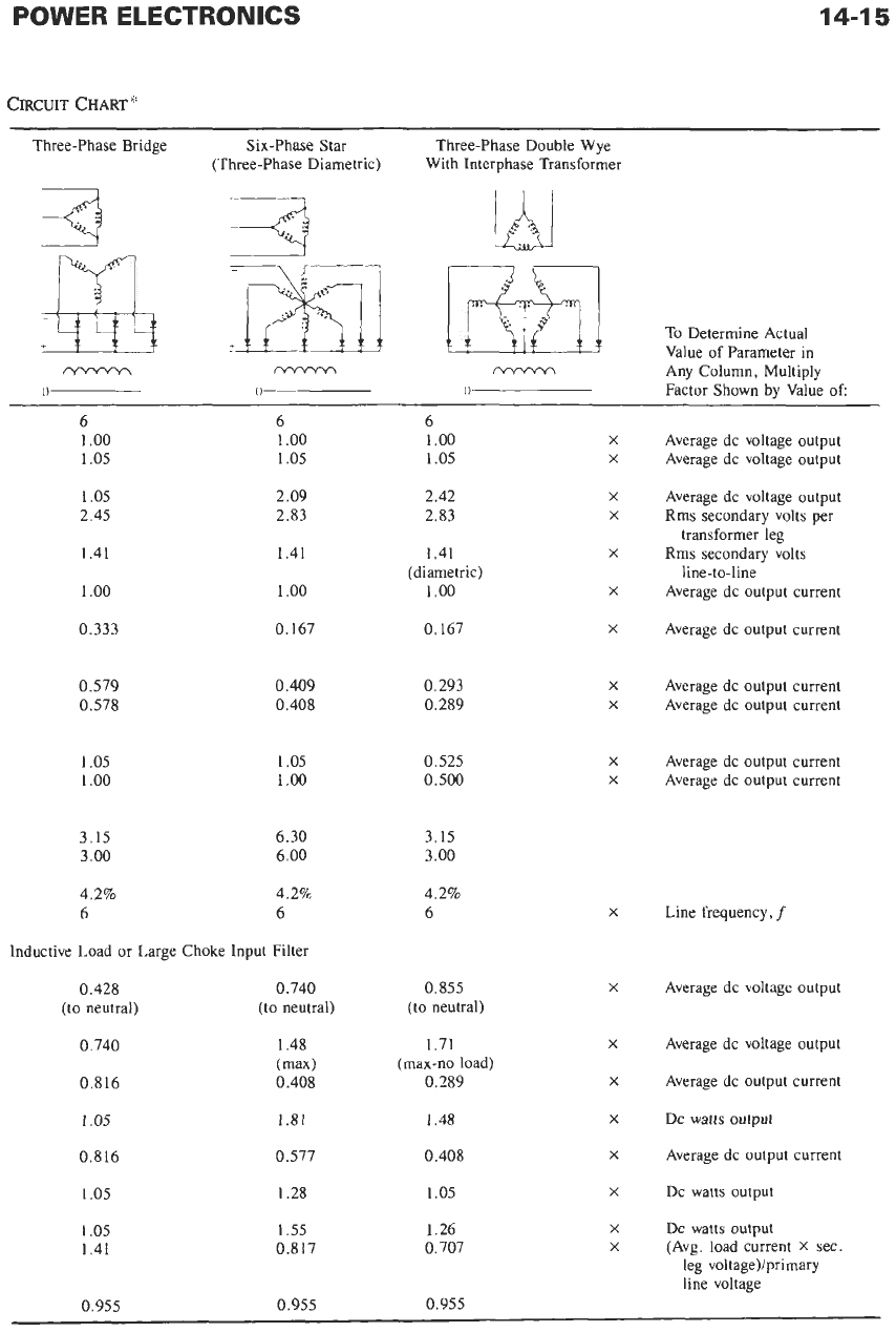
TABLE
3.
POWER TRANSISTOR
AND
DIODE
WQUIREMENTS
FOR
SWITCH-MODE POWER
SUPPLIES
*
(A)
Buck (Step-Down)
Boost (Step-up) (B)
VOlV,
=
T/(T-T)
vCEO>vO+
ICRl
=
IRL
VCRI
=
VO
QI
d
e
N
0
a
rn
n
m
a
rn
2
0
rn
:
3
B
a
rn
2
G)
5
rn
rn
a
v,
+
t-'-4
If
t
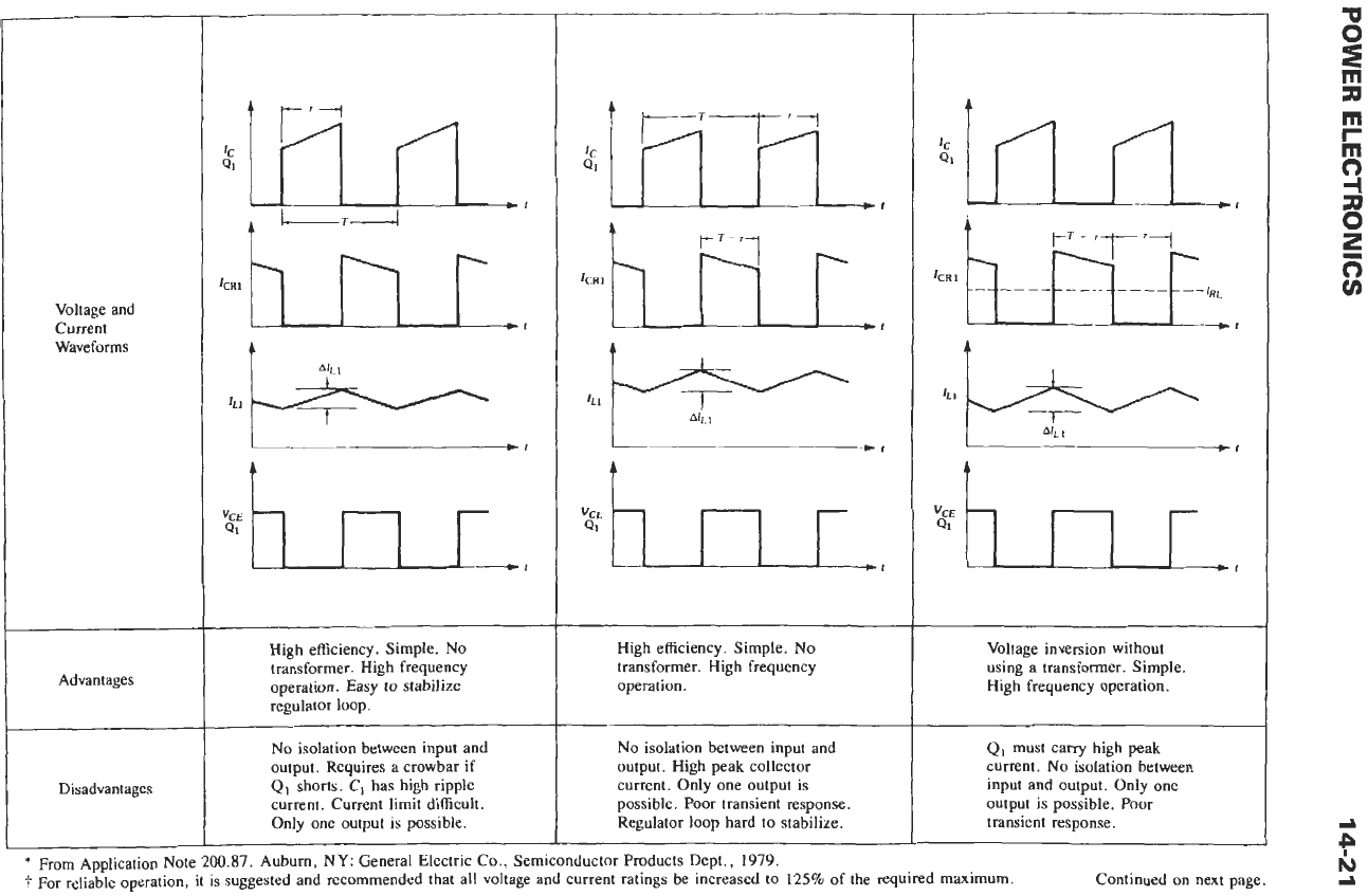
Voltage and
Current
Waveforms
Advantages
Disadvantages
t
For reliable operation, it is suggested and recommended that all voltage and current ratings be increased
to
125%
of the required maximum. Continued on next page.
d
High efficiency. Simple.
No
transformer. High frequency
operation. Easy
to
stabilize
regulator loop.
No
isolation between input and
output. Requires a crowbar if
QI
shorts. C, has high ripple
current. Current limit difficult.
Only one output
is
possible.
t
t-T-7
I
t
High efficiency. Simple.
No
transformer. High frequency
operation.
No
isolation between input and
output. High peak collector
current. Only one output is
possible. Poor transient response.
Regulator loop hard
to
stabilize.
t
2
hnr
t
Voltage inversion without
using a transformer. Simple,
High frequency operation.
QI must carry high
peak
current.
No
isolation between
input and output. Only one
output
is
possible.
Poor
transient response.