Middleton W.M. (ed.) Reference Data for Engineers: Radio, Electronics, Computer and Communications
Подождите немного. Документ загружается.

Circuit
Configuration
Type of
Converter
Ideal
Transfer
Function
Collector
Cumnt(i,)
t
Collector
Voltage
Rating
t
Diode
Currentst
Diode
Voltages
(VRM)~
TABLE
3
(COW).
POWER
TRANSISTOR
AND
DIODE FZQUIRJ2MENTS
FOR
SWITCH-MODE
POWER
SUPPLIES
*
CRI
(D)
Flyback
ICRI
=
IRL
(E)
Forward
(F)
Half Bridge
vCEO
=
VIN
a
e
N
N
=R
m
n
rn
;R
rn
2
0
m
E
3
6
n
rn
2
D
E
m
m
=R
v)
Advantages
I-
1
Disadvantages
t
i-74
t
&-r-
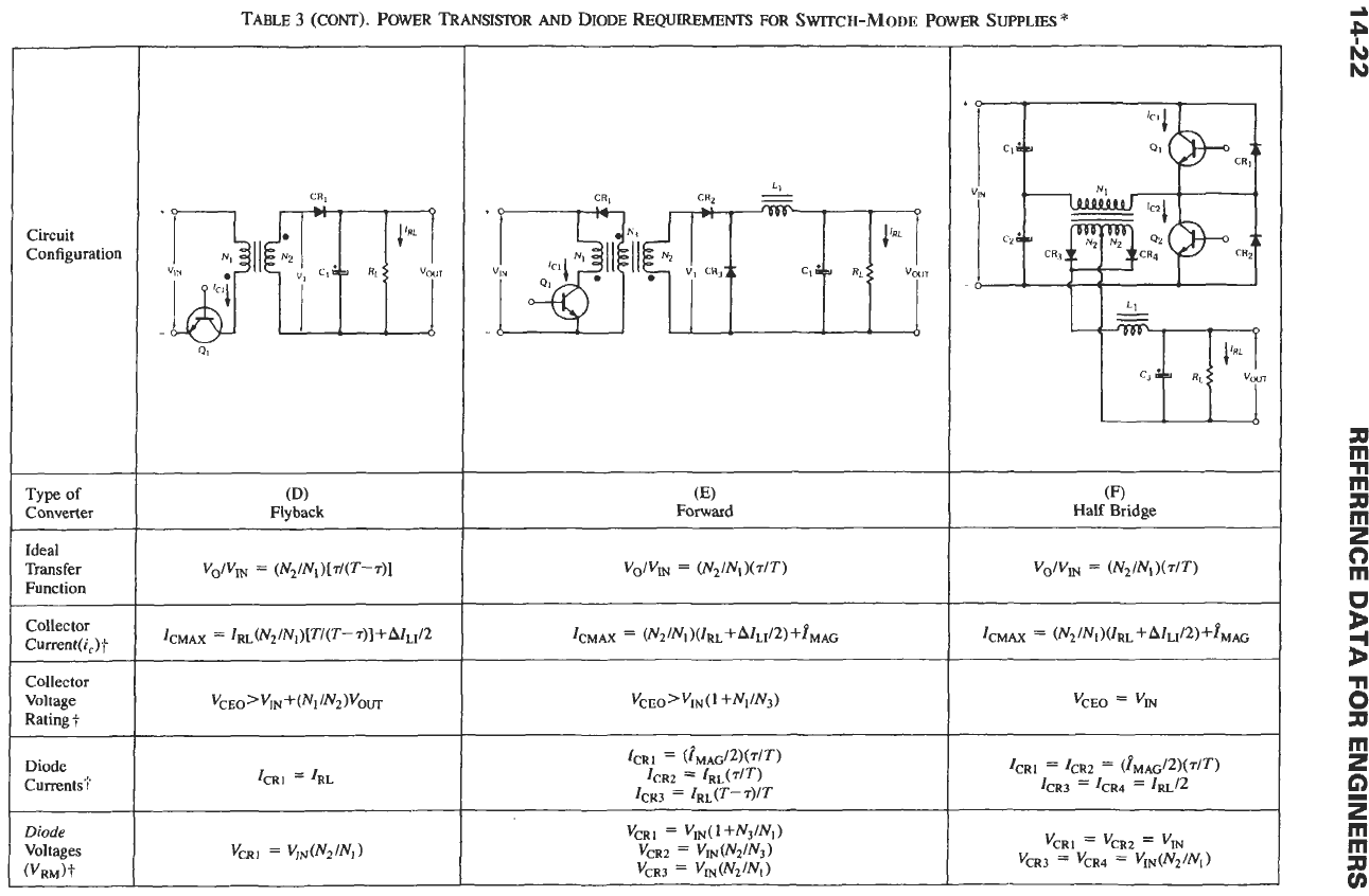
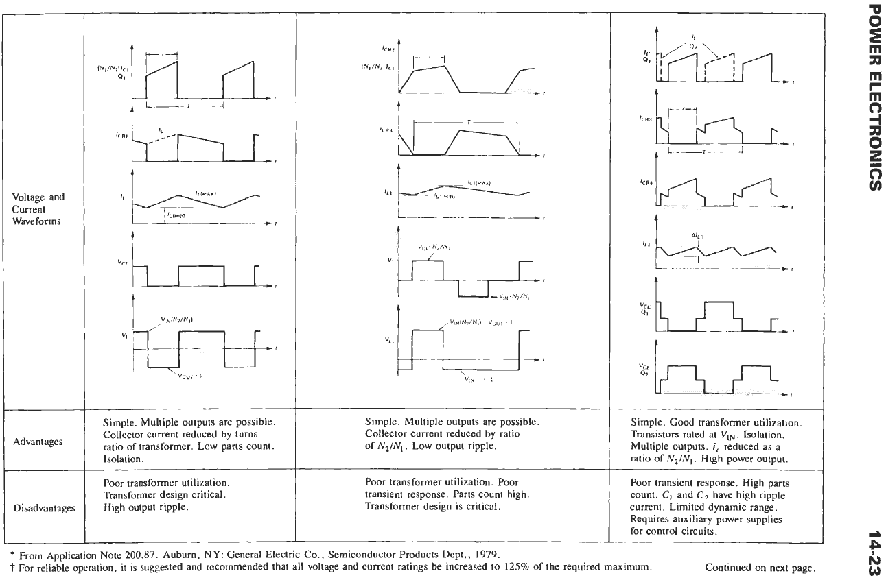
Simple, Multiple outputs are possible.
Collector current reduced by turns
ratio of transformer, Low parts count.
Isolation.
Poor
transformer utilization.
Transformer design critical.
High output ripple.
t
Simple. Multiple outputs are possible
Collector current reduced by ratio
of
N2/NI.
Low output ripple.
Poor
transformer utilization. Poor
transient response. Parts count high.
Transformer design is critical.
Simple. Good transformer utilization.
Transistors rated at
VI,.
Isolation.
Multiple outputs.
i,
reduced as a
ratio
of
N2/NI.
High power output.
Poor transient response. High parts
count.
C,
and
C2
have high ripple
current. Limited dynamic range.
Requires auxiliary power supplies
for control circuits.
*
From Application Note 200.87. Auburn,
NY:
General Electric Co., Semiconductor Products Dept., 1979.
For reliable operation,
it
is suggested and recommended that all voltage and current ratings
be
increased to
125%
of
the required maximum.
Continued on next page.
Circuit
Configuration
Type
of
Converter
Ideal
Transfer
Function
Collector
Current(i,)T
Collector
Voltage
Rating?
Diode
Currents?
Diode
Voltages
(VRM)t
I
TABLE
3
(CONT).
POWER TRANSISTOR
AM)
DIODE
REQUIREMENTS
FOR
SWITCH-MODE
POWER
SUPPLIES
*
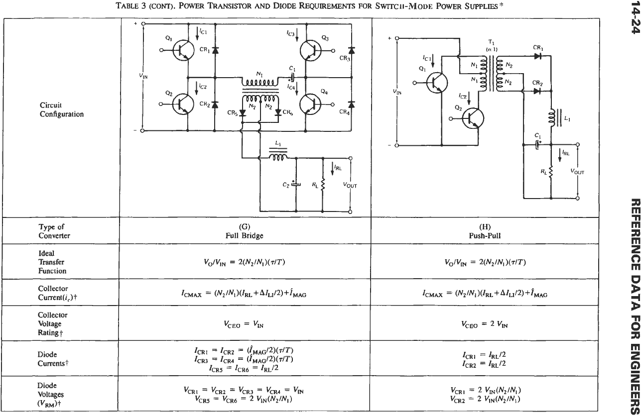
((3
Full Bridge
fO
I
T.
(W
Push-Pull
vCEO
=
VIN
a
e
N
P
311
m
n
m
n
rn
2
0
rn
B
3
6
311
rn
2
G)
2
rn
m
;R
v)
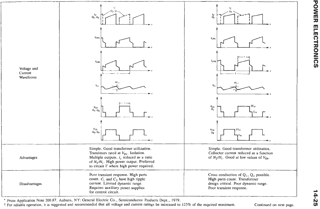
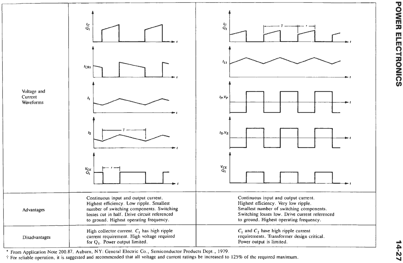
Voltage and
Current
Waveforms
t
ir
kR6k
r(l
,
b
*;
vCE
Q1.
a,
r,,
t
Qz.
Q3
vcE
ut
Simple. Good transformer utilization.
Transistors rated at
VIN.
Isolation.
Multiple outputs.
i,
reduced as a ratio
of
N2/N,.
High power output. Preferred
to circuit
F
where high power required.
Poor transient response. High parts
count.
C,
and
C2
have high ripple
current. Limited dynamic range.
Requires auxiliary power supplies
for control circuit.
t
IC
I
-1
t
Simple. Good transformer utilization.
Collector current reduced as a function
of
N2/N,.
Good at low values of
VIN.
Cross conduction of
Q1,
Q2
possible.
High parts count. Transformer
design critical. Poor dynamic range.
Poor transient response.
Circuit
Configuration
Type
of
Converter
Transfer
Function
Collector
i
Current(i,)t
Collector
Voltage
Rating
Diode
Currents?
Diode
Voltages
!
(VRM)?
TABLE
3
(CONT).
POWER
TRANSISTOR
AND
DIODE
REQUIREMENTS
FOR
SWITCH-MODE
POWER
SUPPLIES
*
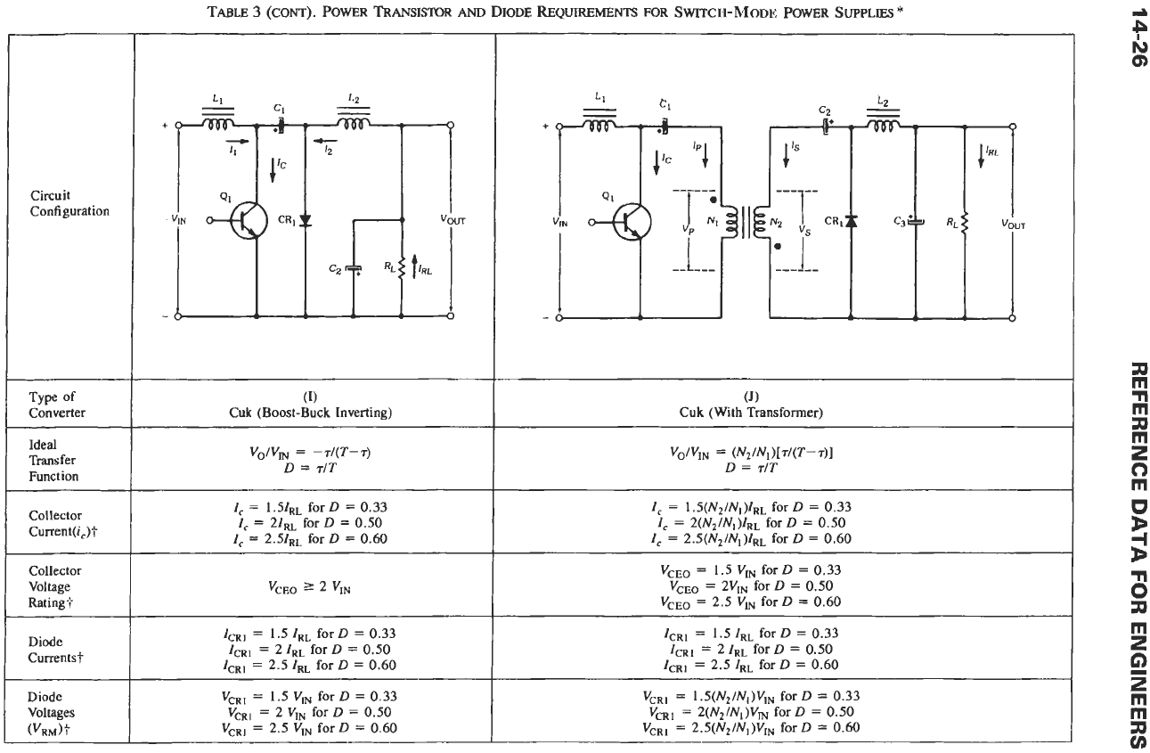
(1)
Cuk (Boost-Buck Inverting)
v,/v,
=
-r/(T-r)
D
=
r/T
I,
=
1.51~~
for
D
=
0.33
I,
=
21RL
for
D
=
0.50
I,
=
2.51RL for
D
=
0.60
'CEO
(J)
Cuk
(With Transformer)
~
I,
=
~.S(N~/NI)IRL for
D
=
0.33
I,
=
2(Nz/Nl)IR~ for
D
=
0.50
I,
=
~.~(N~/NI)IRL for
D
=
0.60
VcEo
=
1.5
VI, for
D
=
0.33
VCEo
=
2Vm for
D
=
0.50
VCEo
=
2.5 VI, for
D
=
0.60
I
Advantages
I
Disadvantages
t
t
~
Continuous input and output current.
Highest efficiency. Low ripple. Smallest
number
of
switching components. Switching
losses cut in half. Drive circuit referenced
to ground. Highest operating frequency.
High collector current.
CI
has high ripple
current requirement. High voltage required
for
QI
.
Power output limited.
-.
t
Q,-
I
I
I
I
I
I
*I
Continuous input and output current.
Highest efficiency.
Very
low
ripple.
Smallest number
of
switching components.
Switching losses low. Drive current referenced
to ground. Highest operating frequency.
C,
and
C,
have high ripple current
requirements. Transformer design critical.
Power output is limited.
I
~
For reliable operation, it is suggested and recommended that all voltage and current ratings be increased to
125%
of the required maximum,
14-28
REFERENCE
DATA
FOR
ENGINEERS
Power
Swlch
ON
VDlfW
@Vt/
RLcad
Power
Switch
OFF
(A)
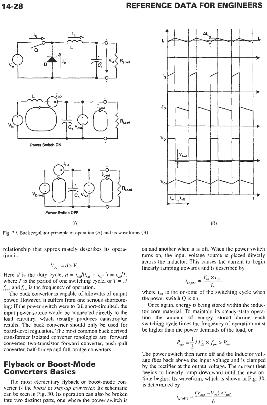
Fig.
29.
Buck
regulator principle
of
operation
(A)
and its waveforms
(B).
k'd
relationship that approximately describes its opera-
tion is
V,,,
=
d
x
V,,
Here
d
is
the duty cycle,
d
=
ton/(ton
+
teff
)
=
ton/T,
where Tis the period of one switching cycle, or
T
= 1/
f,,,
and
f,,
is the frequency of operation.
The buck converter is capable
of
kilowatts of output
power. However, it suffers from one serious shortcom-
ing:
If
the power switch were to fail short-circuited, the
input power source would be connected directly
to
the
load circuitry, which usually produces catastrophic
results. The buck converter should only be used for
board-level regulation. The most common buck derived
transformer isolated converter topologies are: forward
converter, two-transistor forward converter, push-pull
converter, half-bridge and full-bridge converters.
Flyback or Boost-Mode
Converters Basics
The most elementary flyback or boost-mode con-
verter is the
boost
or
step-up converter.
Its schematic
can be seen in Fig.
30.
Its operation can also be broken
into two distinct parts, one where the power switch is
on and another when it is
off.
When the power switch
turns
on, the input voltage source is placed directly
across the inductor. This causes the current to begin
linearly ramping upwards and
is
described by
where
ton
is the on-time of the switching cycle when
the power switch
Q
is
on.
Once again, energy is being stored within the induc-
tor core material. To maintain
its
steady-state opera-
tion the amount
of
energy stored during each
switching cycle times the frequency of operation must
be higher than
the
power demands
of
the load, or
1
<to
=
p;k
x
f,w
'
P0"t
The power switch then
turns
off
and
the
inductor volt-
age flies back above the input voltage and is clamped
by the rectifier at the output voltage. The current then
begins to linearly ramp downward until the new
on-
time begins. Its waveform, which is shown
in
Fig.
30,
is determined by

POWER ELECTRONICS
14-29
Power
Swltch ON
Power
Swltch
OFF
Fig.
30.
Boost regulator principle
of
operation
(A)
and
its
waveforms
(B).
where
teff
is the on-time
of
the switching cycle when
the power switch
Q
is
off.
The operation of the boost converter can be approxi-
mately described by the following relation:
Here
d
is
the
duty cycle,
d
=
to, /(to,,
+
toa
)
=
tOn/T,
where Tis the period
of
one switching cycle, or T
=
l/fsw,
and
f,,
is
the frequency
of
operation.
The
boost converter should also be only used for
board-level regulation.
Table
3
shows the most common switching
con-
verter topologies, their schematic diagrams, transfer
functions, device rating equations, circuit waveforms,
and advantages and disadvantages.
Power Semiconductors in
Switch-Mode Power Supplies
The power semiconductors used in switch-mode
power supplies are thoroughly described
in
the previ-
ous
sections. Therefore the following paragraphs
sum-
marize their properties in relation
to
the switch-mode
power supplies.
Power MOSFETs
Power MOSFETs are very popular for use as power
switches within switch-mode power supplies. MOS-
FETs have some advantages over the bipolar transistor,
such as switching five to ten times faster than bipolar
transistors and being easier to drive and use. The drive
source, however, must be a well-bypassed low-imped-
ance voltage source. This
is
because the gate of a
MOSFET
resembles a capacitor, which must be
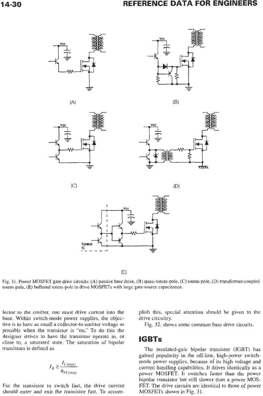
charged and discharged. Fig.
31
shows several power
MOSFET gate drive circuits.
Bipolar PowerTransistors
Bipolar power transistors offer several advantages
over power MOSFETs: They have higher breakdown
voltages, and they are somewhat less expensive for
devices greater than
500
volts.
Bipolar power transistors are current-driven devices.
That is, in order to have a current flowing from the col-
14-30
REFERENCE
DATA
FOR ENGINEERS
IT
L
Fig.
31.
Power MOSFET gate drive circuits:
(A)
passive base drive,
(E)
quasi-totem-pole,
(C)
totem-pole,
(D)
transformer-coupled
totem-pole,
(E)
buffered totem-pole
to
dnve MOSFETs with large gate-source capacitance.
lector
to
the emitter, one must drive current into
the
base. Within switch-mode power supplies, the objec-
tive is
to
have as small a collector-to-emitter voItage as
possible when the transistor is
“on.”
To do
this
the
designer strives to have the transistor operate in,
or
close to, a saturated state. The saturation
of
bipolar
transistors is defined as
For the transistor to switch fast, the drive current
should enter
and
exit the transistor fast.
To
accom-
plish this, special attention should be given to the
drive circuitry.
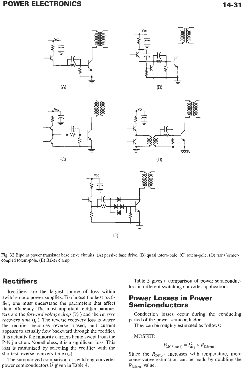
Fig.
32.
shows some common base drive circuits.
IGBTs
The insulated-gale bipolar transistor
(IGBT)
has
gained popularity in the off-line, high-power switch-
mode power supplies, because of its high voltage and
current handling capabilities.
It
drives identically as a
power
MOSFET.
It
switches faster than the power
bipolar transistor but still slower than a power
MOS-
FET. The drive circuits are identical to those of power
MOSFETs
shown
in
Fig.
31.
POWER ELECTRONICS
14-31
Fig.
32
Bipolar power transistor base drive circuits:
(A)
passive
base drive,
(B)
quasi totem-pole,
(C)
totem-pole,
(D)
transformer-
coupled totem-pole,
(E)
Baker clamp.
Rectifiers
Rectifiers
are
the largest source
of
loss
within
switch-mode power supplies. To choose the best recti-
fier, one must understand the parameters that affect
their efficiency. The most important rectifier parame-
ters are the
forward voltage drop
(V,
)
and the
reverse
recovery time (t,).
The reverse recovery loss is where
the rectifier becomes reverse biased, and current
appears
to
actually flow backward through the rectifier.
It
is actually the minority carriers being swept from the
P-N
junction. Nonetheless, it is a significant
loss.
This
loss
is minimized by selecting the rectifier with the
shortest reverse recovery time
(t,).
The summarized comparison
of
switching converter
power semiconductors is given in Table
4.
Table
5
gives a comparison
of
power semiconduc-
tors in different switching converter applications.
Power
Losses
in Power
Semiconductors
Conduction losses occur during the conducting
They can be roughly estimated as follows:
MOSFET
period
of
the power semiconductor.
PMOS(condj
=
'Zvg
x
Ros(on)
Since the
RDs(on)
increases with temperature, more
conservative estimation can be made by doubling the
RDS(onj