Middleton W.M. (ed.) Reference Data for Engineers: Radio, Electronics, Computer and Communications
Подождите немного. Документ загружается.

14-42
REFERENCE
DATA
FOR ENGINEERS
INPUT
CAPACITANCE
----
---8uF
EFFECTIVE LOAD RESISTANCE
=
ACTUAL
LOAD
RESISTANCE PLUS
FILTER-CHOKE RESISTANCE IN
OHMS
Fig.
50.
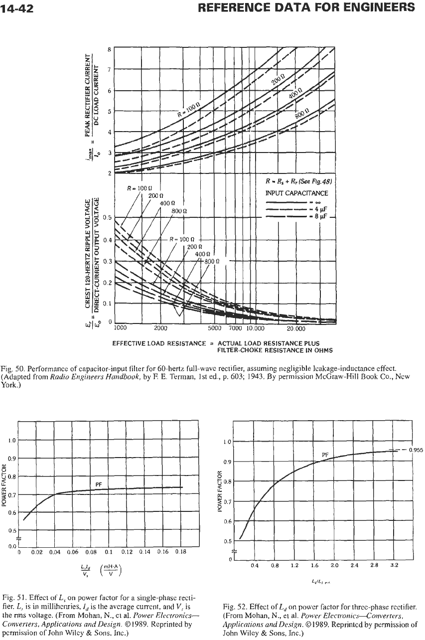
Performance of capacitor-input filter for 60-hertz full-wave rectifier, assuming negligible leakage-inductance effect.
(Adapted from
Radio Engineers Handbook,
by F.
E.
Terman, 1st
ed.,
p. 603;
1943.
By permission McGraw-Hill
Book
CO.,
New
York.)
(F)
Fig.
51.
Effect of
L,
on power factor for a single-phase recti-
fier.
L,
is
in
millihenries,
Id
is the average current, and
V,
is
the
rms
voltage. (From Mohan,
N.,
et
al.
Power Electronics-
Converters, Applications and Design.
01989.
Reprinted by
permission of John Wiley
&
Sons, lnc.)
Fig.
52.
Effect
of
L,
on
power factor for three-phase rectifier.
(From Mohan,
N.,
et al.
Power Electronics-Converters,
Applications and Design.
01989.
Reprinted by permission of
John Wiley
&
Sons, Inc.)
POWER ELECTRONICS
14-43
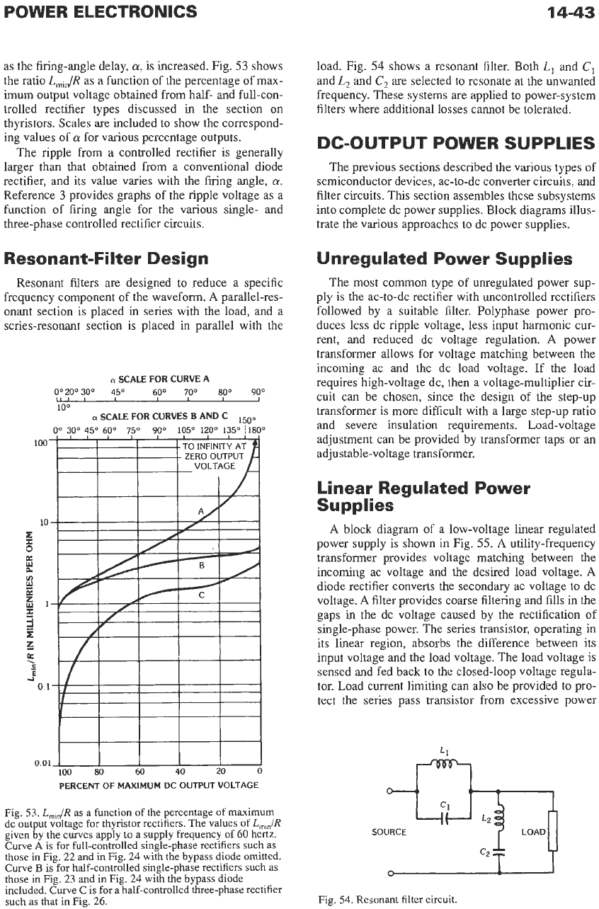
as the firing-angle delay,
a,
is increased. Fig.
53
shows
the ratio
L,,/R
as a function of the percentage of max-
imum output voltage obtained from half- and full-con-
trolled rectifier types discussed
in
the section
on
thyristors. Scales are included to show
the
correspond-
ing values of
a
for various percentage outputs.
The ripple from a controlled rectifier is generally
larger than that obtained from a conventional diode
rectifier, and its value varies with the firing angle,
a.
Reference
3
provides graphs of the ripple voltage as a
function of firing angle for the various single- and
three-phase controlled rectifier circuits.
Resonant-Filter Design
Resonant filters
are
designed to reduce a specific
frequency component of the waveform.
A
parallel-res-
onant section
is
placed in series with the load, and a
series-resonant section is placed
in
parallel with the
n
SCALE FOR CURVE
A
Oo200300 45"
60°
70°
80°
90"
100
a
SCALE FOR CURVES
B
AND C
Oo
30°
45O
60°
75O
90°
105O
EOo
135O
180°
LII
I
I
ISoo
IIII
I I
I
III
100
I
I
TO
INFINITY
AT
,
ZEROOUTPUT
o.oiJ
I
I
I
I
I
100
80
60
40
20
0
PERCENT
OF
MAXlMUM DC OUTPUT VOLTAGE
Fig.
53.
L,,/R
as a function of the percentage of maximum
dc output voltage for thyristor rectifiers. The values of
L,,/R
given by the curves apply to a supply frequency
of
60 hertz.
Curve
A
is for full-controlled single-phase rectifiers such as
those in Fig. 22 and
in
Fig. 24 with the bypass diode omitted.
Curve
B
is for half-controlled single-phase rectifiers such as
those in Fig. 23 and in Fig. 24 with the bypass diode
included. Curve Cis for a half-controlled three-phase rectifier
such as that in Fig. 26.
load. Fig.
54
shows a resonant filter. Both
L,
and
C,
and
L,
and
C,
are
selected to resonate at the unwanted
frequency. These systems are applied to power-system
filters where additional losses cannot be tolerated.
DC-OUTPUT POWER SUPPLIES
The previous sections described the various types of
semiconductor devices, ac-to-dc converter circuits, and
filter circuits. This section assembles these subsystems
into complete dc power supplies. Block diagrams illus-
trate the various approaches to dc power supplies.
Unregulated Power Supplies
The most common type of unregulated power sup-
ply
is
the ac-to-dc rectifier with uncontrolled rectifiers
followed by a suitable filter. Polyphase power pro-
duces less dc ripple voltage, less input harmonic CLU-
rent, and reduced dc voltage regulation.
A
power
transformer allows for voltage matching between the
incoming ac and the dc load voltage. If the load
requires high-voltage dc, then a voltage-multiplier cir-
cuit can be chosen, since the design of the step-up
transformer is more difficult with a large step-up ratio
and severe insulation requirements. Load-voltage
adjustment can be provided by transformer taps or an
adjustable-voltage transformer.
Linear Regulated Power
Supplies
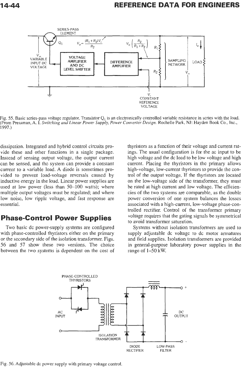
A
block diagram of
a
low-voltage linear regulated
power supply is shown in Fig.
55.
A
utility-frequency
transformer provides voltage matching between the
incoming ac voltage and
the
desired load voltage.
A
diode rectifier converts the secondary ac voltage to dc
voltage.
A
filter provides coarse filtering and fills in the
gaps in the dc voltage caused by the rectification of
single-phase power. The series transistor, operating in
its linear region, absorbs the difference between its
input voltage and
the
load voltage. The load voltage
is
sensed and fed back to the closed-loop voltage regula-
tor. Load current limiting can also be provided to pro-
tect the series pass transistor from excessive power
c2
lY
T
Fig. 54. Resonant filter circuit.
4
4-44
/
1
(RI+
Rz)
V,
v,=
~
R2
SAMPLING
NETWORK
I:
1
VOLTAGE
AMPLIFIER DIFFERENCE
ANDDC
-
AMPLIFIER
v,n
VARIABLE
INPUTDC
-
VOLTAGE
LEVEL SHIFTER
REFERENCE
DATA
FOR ENGINEERS
SERIES-PASS
1
v,
CONSTANT
REFERENCE
VOLTAGE
Fig.
55.
Basic series-pass voltage regulator. Transistor
Q1
is
an
electronically controlled variable resistance in series with the load.
(From
Pressman,
A.
I.
Switching and Linear Power
Supply,
Power Converter Design.
Rochelle
Park,
NJ:
Hayden
Book
Co..
Inc.,
1997.)
dissipation. Integrated and hybrid control circuits pro-
vide these and other functions in a single package.
Instead of sensing output voltage, the
output
current
can be sensed, and the system can provide a constant
current to a variable load.
A
diode is sometimes pro-
vided
to
prevent load-voltage reversals caused by
inductive energy in the load. Linear power supplies are
used at low power (less than
50-100
watts); where
multiple output voltages must be regulated; and where
low noise, low ripple voltage, and fast response
are
essential.
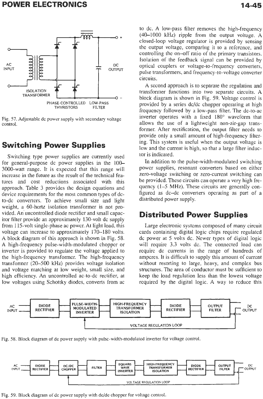
P hase-Cont rol Power Supplies
Two basic dc power-supply systems are configured
with phase-controlled thyristors either
on
the primary
or the secondary side of the isolation transformer. Figs.
56
and
57
show these two versions. The choice
between the two systems is dependent on the cost
of
thyristors as a function of their voltage and current rat-
ings. The usual configuration is for the ac input
to
be
high voltage and the dc load
to
be low voltage and high
current. Placing the thyristors in the primary allows
high-voltage, low-current thyristors
to
provide the con-
trol of the output voltage.
If
the thyristors are located
on the low-voltage side
of
the transformer, they must
be rated at high current and low voltage. The efficien-
cies of the two systems are comparable, as the double
power conversion of one system balances the losses
associated with a high-current, low-voltage phase-con-
trolled rectifier. Control of the transformer primary
voltage requires that the gating signals be symmetrical
to
avoid transformer saturation.
Systems without isolation transformers are used to
supply adjustable dc voltage
to
dc motor armatures
and field supplies. Isolation transformers are provided
in general-purpose laboratory power supplies in the
range
of
1-50
kW.
PHASE-CONTROLLED
THYRISTORS
-
-
AC DC
INPUT OUTPUT
ISOLATION
Ii
TRANSFORMER
9-
DIODE LOW-PASS
RECTIFIER FILTER
Fig.
56.
Adjustable dc power supply with primary voltage control
14-45
DIODE
RECTIFIER
PULSE-WIDTH-
-
HIGH-FREQUENCY
-
INVERTER
-
ISOLATION
-
MODULATED TRANSFORMER
AC
-
DIODE
-
INPUT
-
RECTIFIER
-
-
-
-
TRANSFORMER
-
-
-
OUTPUT
DC
-
FILTER
OUTPUT
PHASE-CONTROLLED LOW-PASS
THYRISTORS FILTER
Fig.
57.
Adjustable dc power supply with secondary voltage
control.
Switching Power Supplies
Switching type power supplies are currently used
for general-purpose dc power supplies in the 100-
3000-watt range. It is expected that this range will
increase in the future as the result of the technical fea-
tures and cost reductions associated with this
approach. Table
3
provides the design equations and
device requirements for the most common types of dc-
to-dc converters. To achieve small size and light
weight, a 60-hertz isolation transformer is not pro-
vided. Anuncontrolled diode rectifier and small capac-
itor filter provide an approximately 130-volt dc supply
from 115-volt single-phase ac power. At light load, this
voltage can increase to approximately
170-180
volts.
A block diagram of this approach is shown in Fig.
58.
A
high-frequency pulse-width-modulated chopper or
inverter is provided to regulate the voltage applied to
the high-frequency transformer. The high-frequency
transformer
(20-500
kHz)
provides voltage isolation
and voltage matching at low weight, small size, and
high efficiency. An uncontrolled ac-to-dc rectifier, at
low voltages using Schottky diodes, converts from ac
to dc. A low-pass filter removes the high-frequency
(40-1000
kHz) ripple from the output voltage. A
closed-loop voltage regulator is provided by sensing
the output voltage, comparing it to a reference, and
controlling the on-off ratio of the primary transistors.
Isolation of the feedback signal can be provided by
optical couplers or voltage-to-frequency converters,
pulse transformers, and frequency-to-voltage converter
circuits.
A second approach is
to
separate the regulation and
transformer functions into two separate circuits. A
block diagram is shown
in
Fig.
59.
Voltage control is
provided by a series dc/dc chopper operating at high
frequency followed by a low-pass filter. The dc-to-ac
inverter operates with a fixed 180" waveform that
allows the use of a lightweight non-air-gap trans-
former. After rectification, the output filter needs to
provide only a small amount of high-frequency filter-
ing. This system is useful when the output voltage is
low and the current
is
high, so that a large filter induc-
tor is indicated.
In
addition to the pulse-width-modulated switching
power supplies, resonant converters based on either
zero-voltage switching or zero-current switching can
be provided. These circuits can operate a very high fre-
quency
(1-5
MHz). These circuits are generally con-
figured as dc-dc converters operating as part of a
distributed power supply.
Distributed Power Supplies
Large electronic systems composed of many circuit
cards containing digital logic chips require regulated
dc power at
5
volts dc. Newer types of digital logic
will require 3.3 volts dc. The connected load can
require dc currents in the range of hundreds
of
amperes. It is difficult to supply this amount of current
without resorting to large, heavy, and complex bus
structures. The area of conductor must be sufficient to
keep the load regulation less than the lowest voltage
required by the digital logic. A way
to
reduce this
I
VOLTAGE REGULATION LOOP
I
Fig.
58.
Block diagram
of
dc power supply with pulse-width-modulated inverter
for
voltage control.
HIGH.FREQUENCY
-
RECTIFIER
-
DIODE
TRANSFORMER
ISOlATlON
VOLTAGE
REGULATION
LOOP
Fig.
59.
Block diagram
of
dc power supply with dc/dc chopper for voltage control
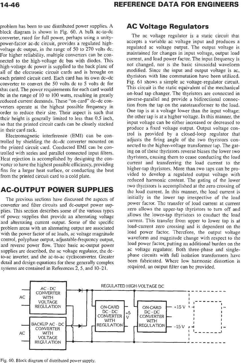
problem has been to use distributed power supplies.
A
block diagram is shown in Fig.
60.
A
bulk ac-to-dc
converter, rated for full power, perhaps using a unity-
power-factor ac-dc circuit, provides a regulated high-
voltage dc output, in the range of
50
to
270
volts dc.
For higher reliability, multiple converters can be con-
nected to the high-voltage dc bus with diodes. This
high-voltage dc power is supplied to the back plane of
all of the electronic circuit cards and
is
brought
on
each printed circuit card. Each card has its own dc-dc
converter to convert the
50
volts dc to
5
volts dc for
that card. The power requirements for each card would
be in the range of
10
to
100
watts, resulting in greatly
reduced current demands. These "on-card" dc-dc con-
verters operate at the highest possible frequency in
order to reduce their size. Their aspect is such that
their height is generally limited to less than
0.5
inch,
so
that the printed circuit cards can be closely stacked
in their card rack.
Electromagnetic interference (EMI) can be con-
trolled by shielding the dc-dc converter mounted
on
the printed circuit card. Conducted EM1 can be con-
trolled with series and parallel connected input filters.
Heat rejection is accomplished by designing the con-
verter
to
have the highest possible efficiency, providing
fins for a larger heat surface, or conducting the heat
from the printed circuit card to a cold plate.
-
AC
-
-
AC
-
AC-OUTPUT POWER SUPPLIES
REGULATED HIGH-VOLTAGE DC
Ll
-
VI
*
-
-
_---______
AC
-
DC
CONVERTER
WITH
VOLTAGE
I
f
I-----_-
I
I
ON-CARD
I'
REGULATION
-
ON-CARD
-
-
+I5
v
-I
I
I
I
I
I
I
I
REGULATION
-
-15
v
I
4
'
'----_--I
WITH
I
I'
BACKUP AC
-
DC
++
REGULATION
-
CONVERTER
VOLTAGE
I
-
-
REGULATION
-
-
-.---------
The previous sections have discussed the aspects of
converter and filter circuits and dc-output power sup-
plies. This section describes some of the various types
of power supplies that provide an alternating voltage
and alternating current output. Some of the specific
problem areas with an alternating output
are
associated
with
the
power factor of ac loads, ac voltage magnitude
control, polyphase output, adjustable-frequency output,
and reverse power flow. Three basic ac-output power
supplies are described, the ac voltage regulator, the dc-
to-ac inverter, and
the
ac-to-ac cycloconverter. Greater
detail and design equations for these generally complex
systems are contained
in
References
2,5,
and
1CL2
1.
AC
Voltage Regulators
The ac voltage regulator is a static circuit that
accepts a variable ac voltage input and produces a
regulated ac voltage output. The output voltage is
maintained for changes in input voltage, output load
current, and load power factor. The input frequency is
not changed, nor is the basic sinusoidal waveform
modified. Since the input and output voltage is ac,
thyristors with line commutation have been utilized.
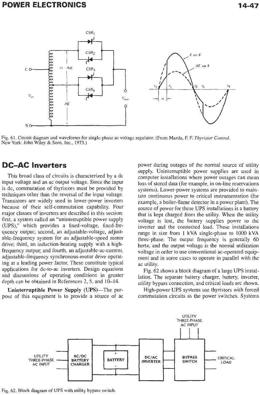
Fig.
61
shows a simple ac voltage-regulator circuit.
This circuit is the static equivalent of the mechanical
on-load tap changer. The thyristors are connected in
inverse-parallel and provide a bidirectional connec-
tion from the tap
on
the autotransformer to the load.
One tap is at a voltage lower than the input voltage;
the other tap is at a higher voltage.
In
this manner, the
input voltage can be either increased or decreased to
produce a fixed voltage output. Output voltage con-
trol is provided by a closed-loop regulator that
adjusts the firing angle of the two thyristors con-
nected to the higher-voltage transformer tap. The gat-
ing
on
of these thyristors reverse biases the lower two
thyristors, causing them to cease conducting the load
current and transferring the load current to the
higher-tap thyristors. More than two taps can be pro-
vided to develop a regulated output voltage with
reduced harmonic content. The gating of the lower
two thyristors is accomplished at the zero crossing of
the load current.
In
this manner, the load current is
initially in the lower tap irrespective of the load
power factor. The transfer of load current at current
zero allows the upper-tap thyristors to turn off and
allows the lower-tap thyristors to conduct the load
current. This transfer from upper to lower tap is at
load-current zero crossing and is dependent
on
the
load power factor. Therefore, the output voltage
waveform and magnitude change with respect to the
load power factor, putting an additional burden
on
the
ac voltage regulator. Both three-phase and single-
phase circuits with full isolation transformers have
been fabricated. Where low harmonic distortion is
required,
an
output filter can be provided.
Fig.
60.
Block
diagram
of
distributed
power
supply.
14-47
-
1
-
-
+
UTILITY
ACIDC DCIAC
INVERTER
-
THREE-PHASE
-
BATTERY BA‘ITERY
AC INPUT
CHARGER
-
-
-
-
Fig. 61. Circuit diagram and waveforms for single-phase ac voltage regulator.
(From
Mazda, F. F.
Thyristor Control
New
York:
John
Wiley
&
Sons,
Inc., 1973.)
-
BYPASS
CRITICAL
SWITCH
-
LOAD
-
DC-AC
Inverters
This broad class of circuits is characterized by a dc
input voltage and
an
ac output voltage. Since the input
is dc, commutation of thyristors must be provided by
techniques other than the reversal of
the
input voltage.
Transistors
are
widely used
in
lower-power inverters
because of their self-commutation capability. Four
major classes of inverters are described in this section:
first, a system called an “unintermptible power supply
(UPS),”
which provides a fixed-voltage, fixed-fre-
quency output; second,
an
adjustable-voltage, adjust-
able-frequency system for
an
adjustable-speed motor
drive; third, an induction-heating supply with a high-
frequency output; and fourth, an adjustable-ac-current,
adjustable-frequency synchronous-motor drive operat-
ing at a leading power factor. These constitute typical
applications for dc-to-ac inverters. Design equations
and discussions of operating conditions
in
greater
depth can be obtained in References
2,
5,
and
10-14.
Uninterruptible Power Supply (UPShThe pur-
pose of this equipment is to provide a source
of
ac
power during outages of the normal source of utility
supply. Uninterruptible power supplies are used
in
computer installations where power outages can mean
loss of stored data (for example,
in
on-line reservations
systems). Lower-power systems are provided to main-
tain continuous power to critical instrumentation (for
example, a boiler-flame detector in a power plant). The
source
of
power for these
UPS
installations is a battery
that is kept charged from the utility. When the utility
voltage is lost,
the
battery supplies power to the
inverter and the connected load. These installations
range in size from
1
kVA single-phase
to
1000
kVA
three-phase. The output frequency is generally
60
hertz, and the
output
voltage is the
normal
utilization
voltage in order to use conventional ac-operated equip-
ment and in some cases to operate
in
parallel with the
ac utility.
Fig.
62
shows a block diagram of a large
UPS
instal-
lation. The separate battery charger, battery, inverter,
utility bypass connection, and critical loads
are
shown.
High-power
UPS
systems use thyristors with forced
commutation circuits as
the
power switches. Systems
UTILITY
THREE-PHASE
AC INPUT
n
Fig. 62. Block diagram
of
UPS with utility bypass switch.
14-48
with ratings less than
200
kVA
now use power transis-
tors
or insulated-gate bipolar transistors as the power
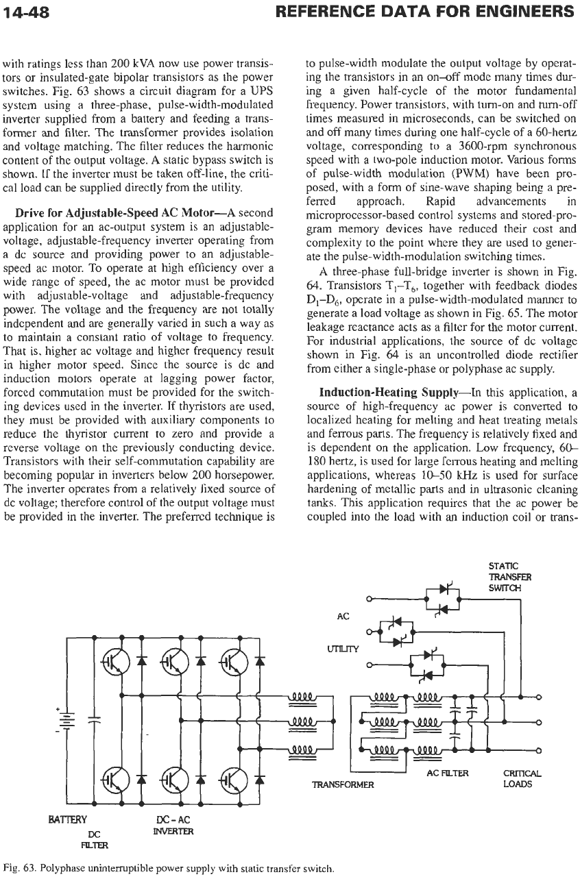
switches. Fig. 63 shows a circuit diagram for a UPS
system using a three-phase, pulse-width-modulated
inverter supplied from a battery and feeding a trans-
former and filter. The transformer provides isolation
and voltage matching. The filter reduces the harmonic
content of the output voltage.
A
static bypass switch is
shown. If
the
inverter must be taken off-line, the criti-
cal load can be supplied directly from the utility.
Drive
for
Adjustable-Speed AC Motor-A
second
application for an ac-output system is an adjustable-
voltage, adjustable-frequency inverter operating from
a dc source and providing power to
an
adjustable-
speed ac motor. To operate at high efficiency over a
wide range of speed, the ac motor must be provided
with adjustable-voltage and adjustable-frequency
power. The voltage and
the
frequency are not totally
independent and
are
generally varied in such a way as
to maintain a constant ratio of voltage
to
frequency.
That
is,
higher ac voltage and higher frequency result
in higher motor speed. Since the source is dc and
induction motors operate at lagging power factor,
forced commutation must be provided for the switch-
ing devices used in the inverter. If thyristors are used,
they must be provided with auxiliary components
to
reduce the thyristor current to zero and provide a
reverse voltage
on
the previously conducting device.
Transistors with their self-commutation capability
are
becoming popular in inverters below
200
horsepower.
The inverter operates from a relatively fixed source
of
dc voltage; therefore control of the output voltage must
be provided in the inverter. The preferred technique is
to pulse-width modulate the output voltage by operat-
ing the transistors in an
on-off
mode many times dur-
ing a given half-cycle of the motor fundamental
frequency. Power transistors, with
turn-on
and
turn-off
times measured in microseconds, can be switched
on
and
off
many times during one half-cycle
of
a 60-hertz
voltage, corresponding to a 3600-rpm synchronous
speed with a two-pole induction motor.
Various
forms
of pulse-width modulation (PWM) have been pro-
posed, with a form of sine-wave shaping being a pre-
ferred approach. Rapid advancements
in
microprocessor-based control systems and stored-pro-
gram memory devices have reduced their cost and
complexity to
the
point where they are used
to
gener-
ate the pulse-width-modulation switching times.
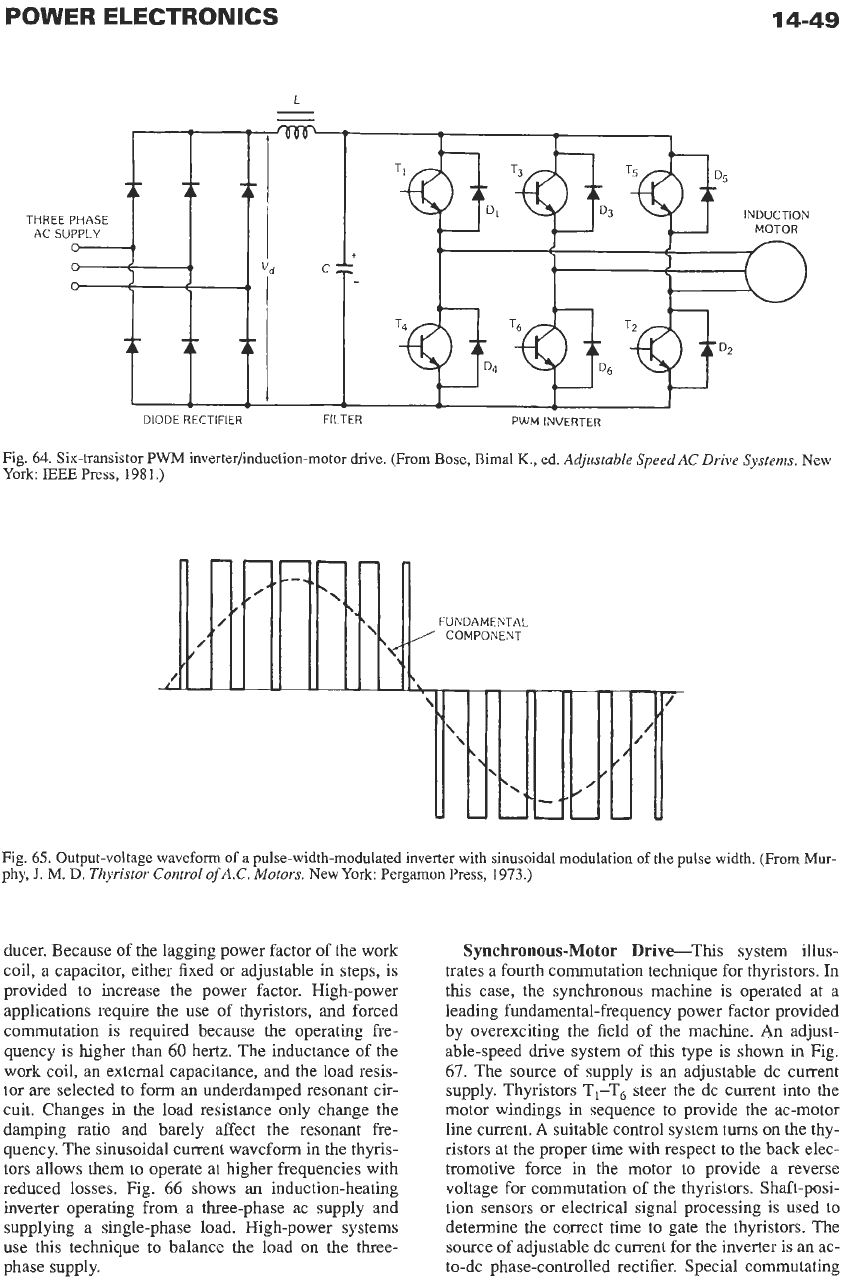
A
three-phase full-bridge inverter is shown in Fig.
64. Transistors T,-T6, together with feedback diodes
D&, operate
in
a pulse-width-modulated manner to
generate a load voltage as shown in Fig. 65. The motor
leakage reactance acts as a filter for the motor current.
For industrial applications, the source
of
dc voltage
shown in Fig.
64
is an uncontrolled diode rectifier
from either a single-phase or polyphase ac supply.
Induction-Heating
Supply-In
this application, a
source of high-frequency ac power is converted to
localized heating for melting and heat treating metals
and ferrous parts. The frequency is relatively fixed and
is dependent
on
the application. Low frequency,
60-
180
hertz, is used for large ferrous heating and melting
applications, whereas
10-50
Wz
is
used for surface
hardening of metallic parts and in ultrasonic cleaning
tanks. This application requires that the ac power be
coupled into the load with an induction coil or trans-
STATIC
TRANSFER
TRANSFORMER
LOADS
BATFRY
DC-AC
Dc
mm
mTER
Fig.
63.
Polyphase unintermptible power supply with static transfer switch.
POWER
ELECTRONICS
14-49
L
-
-
THREE
AC
SU
DIODE
RECTIFIER FILTER
PWM
INVERTER
Fig.
64.
Six-transistor
PWM
inverter/induction-motor
drive.
(From
Bose,
Bimal
K.,
ed.
Adjustable Speed AC Drive Systems.
New
York
BEE
Press,
1981.)
Fig.
65.
Output-voltage waveform
of
a pulse-width-modulated inverter with sinusoidal modulation of
the
pulse width. (From Mur-
phy,
J.
M.
D.
Thyristor Control
of
A.C. Motors.
New York Pergamon Press,
1973.)
ducer. Because of the lagging power factor of the work
coil, a capacitor, either fixed or adjustable in steps, is
provided to increase the power factor. High-power
applications require the use of thyristors, and forced
commutation is required because the operating fre-
quency is higher than
60
hertz. The inductance of the
work coil, an external capacitance, and
the
load resis-
tor
are
selected to form an underdamped resonant cir-
cuit. Changes
in
the load resistance only change the
damping ratio and barely affect the resonant fre-
quency. The sinusoidal current waveform in the thyris-
tors allows them to operate at higher frequencies with
reduced losses. Fig.
66
shows
an
induction-heating
inverter operating from a three-phase ac supply and
supplying a single-phase load. High-power systems
use this technique to balance the load on
the
three-
phase supply.
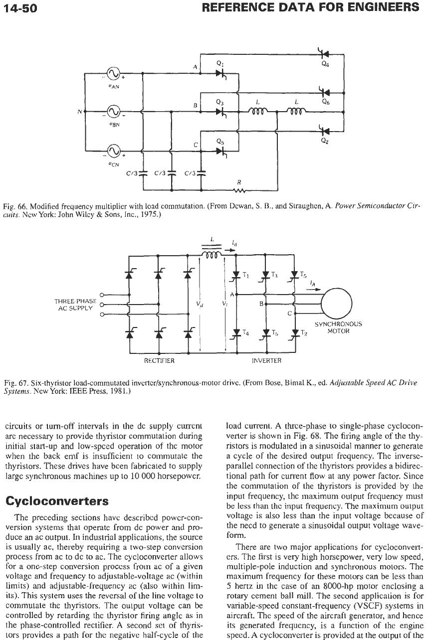
Synchronous-Motor Drive-This system illus-
trates a fourth commutation technique for thyristors. In
this
case, the synchronous machine
is
operated at a
leading fundamental-frequency power factor provided
by overexciting the field of the machine.
An
adjust-
able-speed drive system of
this
type is shown
in
Fig.
67.
The source of supply is an adjustable dc current
supply. Thyristors
TI-T,
steer the dc current into the
motor windings in sequence to provide the ac-motor
line current.
A
suitable control system turns on the thy-
ristors at the proper time with respect to the back elec-
tromotive force in the motor to provide a reverse
voltage for commutation of the thyristors. Shaft-posi-
tion sensors or electrical signal processing is used to
determine the correct time
to
gate the thyristors. The
source of adjustable dc current for the inverter is an ac-
to-dc phase-controlled rectifier. Special commutating
14-50
REFERENCE
DATA
FOR ENGINEERS
N
...
Fig. 66. Modified frequency multiplier with load commutation. (From Dewan,
S.
B., and Straughen,
A.
Power Semiconductor Cir-
cuits.
New
York:
John
Wiley
&
Sons,
Inc., 1975.)
THKEE-PHASE
AC SUPPLY
RECTIFIER INVERTER
Fig. 67. Six-thyristor load-commutated
inverter/synchronous-motor
drive.
(From Bose, Bimal
K.,
ed.
Adjustable Speed AC Drive
Systems.
New York
BEE
Press,
1981.)
circuits or turn-off intervals in the dc supply current
are necessary to provide thyristor commutation during
initial start-up and low-speed operation of the motor
when the back emf is insufficient to commutate the
thyristors. These drives have been fabricated to supply
large synchronous machines up to
10
000
horsepower.
Cyc
I
oco
nver
t
er
s
The preceding sections have described power-con-
version systems that operate from dc power and pro-
duce an ac output.
In
industrial applications, the source
is
usually ac, thereby requiring a two-step conversion
process from ac to dc to ac. The cycloconverter allows
for a one-step conversion process from ac of a given
voltage and frequency to adjustable-voltage ac (within
limits) and adjustable-frequency ac (also within lim-
its). This system uses the reversal of the line voltage to
commutate the thyristors. The output voltage can be
controlled by retarding the thyristor firing angle as in
the phase-controlled rectifier.
A
second set of thyris-
tors provides a path for the negative half-cycle of the
load current.
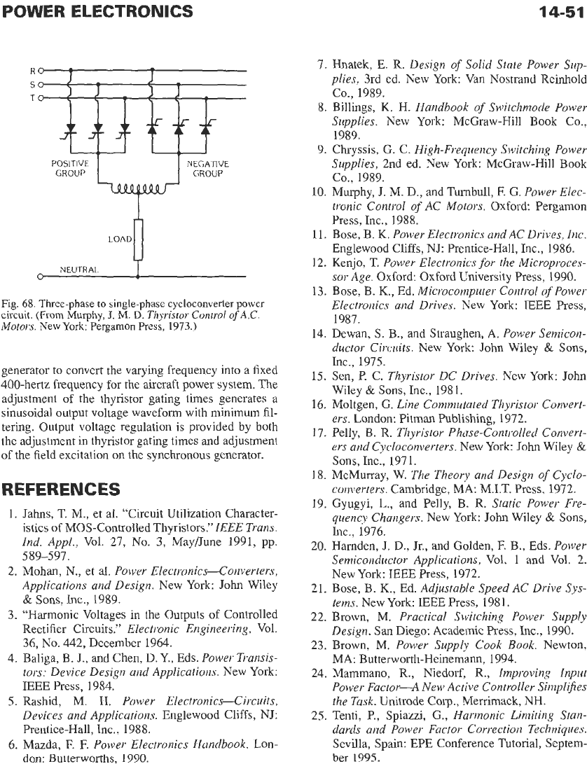
A
three-phase to single-phase cyclocon-
verter is shown in Fig. 68. The firing angle of the thy-
ristors is modulated in a sinusoidal manner to generate
a cycle of the desired output frequency. The inverse-
parallel connection of the thyristors provides a bidirec-
tional path for current flow at any power factor. Since
the commutation of the thyristors is provided by the
input frequency, the maximum
output
frequency must
be less than the input frequency. The maximum output
voltage is also less than the input voltage because of
the need to generate a sinusoidal output voltage wave-
form.
There are
two
major applications for cycloconvert-
ers. The first is very high horsepower, very low speed,
multiple-pole induction and synchronous motors. The
maximum frequency for these motors can be less than
5
hertz
in
the case of an 8000-hp motor enclosing a
rotary cement ball mill. The second application is for
variable-speed constant-frequency (VSCF) systems in
aircraft. The speed of the aircraft generator, and hence
its generated frequency, is a function of the engine
speed.
A
cycloconverter is provided at the
output
of the
POWER
ELECTRONICS
14-51
S
T
NEGATIVE
GROUP
POSITIVE
GROUP
A!-
NEUTRAL
Fig.
68.
Three-phase
to
single-phase cycloconverter
power
circuit.
(From
Murphy,
J.
M.
D.
Thyristor
Control
of
A.C.
Motors.
New
York:
Pergamon
Press,
1973.)
generator to convert the varying frequency into a fixed
400-hertz frequency for the aircraft power system. The
adjustment
of
the thyristor gating times generates a
sinusoidal output voltage waveform with minimum fil-
tering. Output voltage regulation is provided by both
the adjustment in thyristor gating times and adjustment
of
the field excitation on the synchronous generator.
REFERENCES
1. Jahns,
T.
M.,
et al. “Circuit Utilization Character-
istics of MOS-Controlled Thyristors.”
IEEE
Trans.
Ind. Appl.,
Vol. 27, No. 3, May/June 1991, pp.
589-597.
2. Mohan, N., et
al.
Power Electronics-Converters,
Applications and Design.
New York: John Wiley
&
Sons, Inc., 1989.
3. “Harmonic Voltages in the Outputs of Controlled
Rectifier Circuits.”
Electronic Engineering,
Vol.
36,
No.
442, December 1964.
4. Baliga, B. J., and Chen, D. Y., Eds.
Power Traizsis-
tors: Device Design and Applications.
New York:
IEEE Press, 1984.
5.
Rashid,
M.
H.
Power Electronics-Circuits,
Devices and Applications.
Englewood Cliffs, NJ:
Prentice-Hall, Inc., 1988.
6.
Mazda,
E
E
Power Electronics Handbook.
Lon-
don:
Buttenvorths, 1990.
7. Hnatek,
E.
R.
Design
of
Solid State Power
Sup-
plies,
3rd ed. New York:
Van
Nostrand Reinhold
Co., 1989.
8.
Billings,
K.
H.
Handbook
of
Switchmode Power
Supplies.
New York: McGraw-Hill Book Co.,
1989.
9. Chryssis, G. C.
High-Frequency Switching Power
Supplies,
2nd ed. New York: McGraw-Hill Book
Co., 1989.
10.
Murphy, J.
M.
D., and Turnbull,
E
G.
Power Elec-
tronic Control
of
AC Motors.
Oxford Pergamon
Press, Inc., 1988.
11. Bose, B.
K.
Power Electronics andAC Drives, Inc.
Englewood Cliffs, NJ: Prentice-Hall, Inc., 1986.
12. Kenjo, T.
Power Electronics for the Microproces-
sor Age.
Oxford Oxford University Press, 1990.
13. Bose, E.
K.,
Ed.
Microcomputer Control
of
Power
Electronics and Drives.
New York IEEE Press,
1987.
14. Dewan,
S.
B., and Straughen, A.
Powev Semicon-
ductor Circuits.
New York
John
Wiley
&
Sons,
Inc., 1975.
15. Sen,
P.
C.
Thyristor DC Drives.
New York John
Wiley
&
Sons,
Inc., 1981.
16.
Moltgen,
G.
Line Commutated Thyristor Convert-
ers.
London: Pitman Publishing, 1972.
17. Felly, B.
R.
Thyristor Phase-Controlled Convert-
ers and Cycloconverters.
New York: John Wiley
&
Sons, Inc., 1971.
18. McMurray, W.
The Theory and Design
of
Cyclo-
converters.
Cambridge, MA: M.I.T. Press, 1972.
19. Gyugyi,
L.,
and Pelly,
B.
R.
Static Power Fre-
quency Changers.
New York: John Wiley
&
Sons,
Inc., 1976.
20. Harnden,
J.
D.,
Jr., and Golden,
E
B., Eds.
Power
Semiconductor Applications,
Vol.
1
and Vol. 2.
New York: IEEE Press, 1972.
21. Bose, B.
K.,
Ed.
Adjustable Speed AC Drive Sys-
tems.
New York: IEEE Press, 1981.
22. Brown, M.
Practical Switching Power Supply
Design.
San
Diego: Academic Press, Inc., 1990.
23. Brown, M.
Power Supply Cook Book.
Newton,
MA: Butterworth-Heinema, 1994.
24. Mammano,
R.,
Niedorf,
R.,
Improving Input
Power Factor-A New Active Controller Simplifies
the Tusk.
Unitrode
Corp.,
Merrirnack, NH.
25. Tenti, P., Spiazzi, G.,
Harmonic Limiting Stan-
dards and Power Factor Correction Techniques.
Sevilla, Spain: EPE Conference Tutorial, Septem-
ber
1995.