Middleton W.M. (ed.) Reference Data for Engineers: Radio, Electronics, Computer and Communications
Подождите немного. Документ загружается.

14-32
REFERENCE
DATA
FOR ENGINEERS
TABLE
4.
COMPARISOlr
OF
VARIOUS
TRANSISTORS
AND
RECTIFIERS
Transistors Advantages Disadvantages
Bipolars
MOSFETs
IGBT
Rectifiers
Schottky
Ultra-Fast
Low
Vce(sat)
voltage Low gain
High voltage capability
Relatively inexpensive
Base drive is difficult
Limited to approximately
75
liHz
due to switching losses
Nonsquare
SOA*
Easily driven High voltage device
Shares current well
Wide bandwidth
Low
on-resistance for low voltage devices
Square
SOA*
Easily driven
High current capability
Uses
silicon more efficiently
than
MOSFETS
High voltage capability
Square SOA*
Relatively high on-voltage
Existing devices only applicable
up
to
100
Mz.
Tf
<
80
ns
Future demands
z
100
lcHz
and
I",
<
50
ns
Advantages Disadvantages
Low
v,
Very fast High leakage
No
stored charge High capacitance
High voltage capability Stored charge
Low leakage
200
V performance is marginal
Very snappy reverse recovery
*
SOA
=
safe
operating area.
Bipolar and IGBT:
Power rectifier:
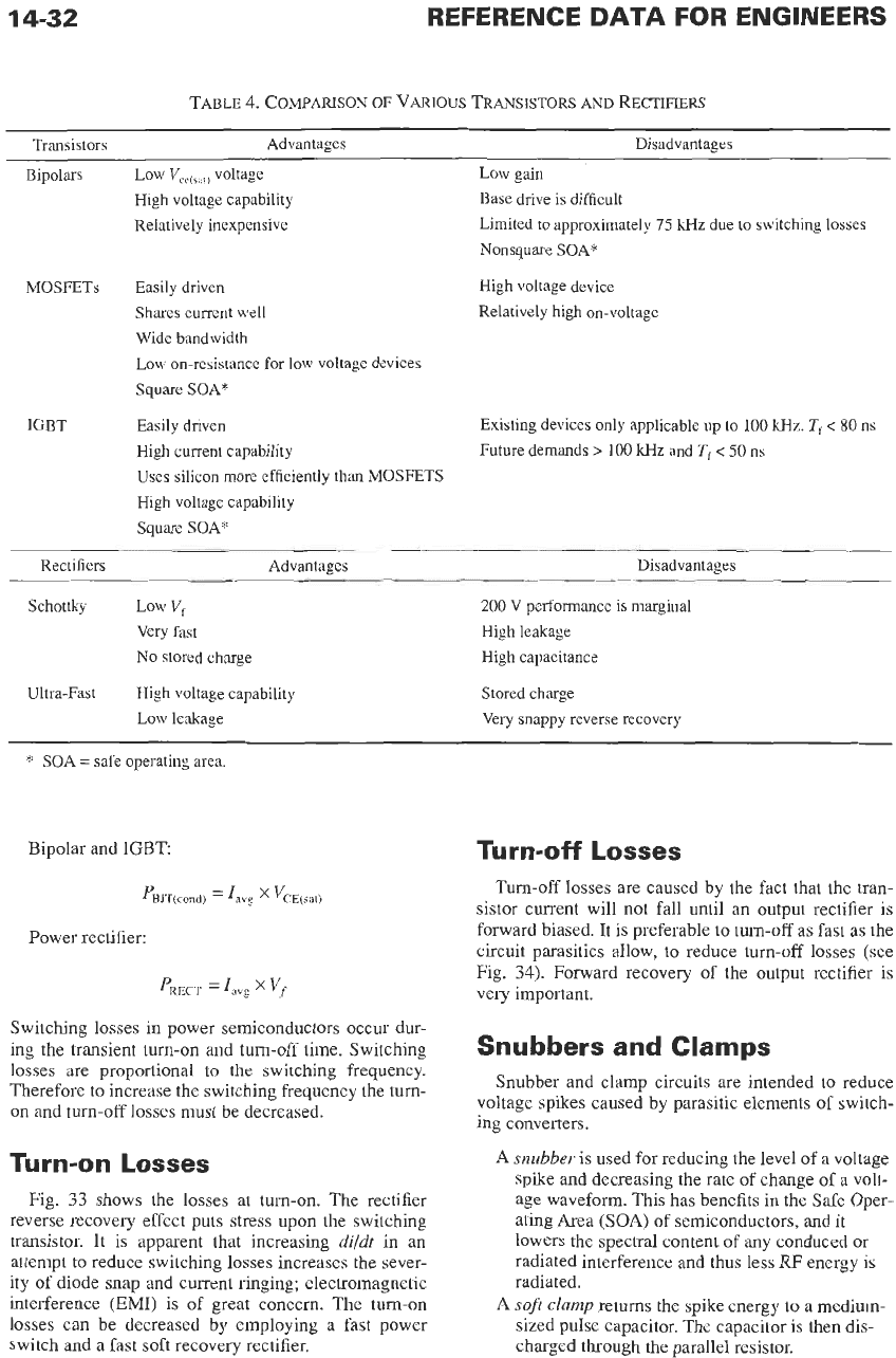
Switching losses in power semiconductors occur dur-
ing the transient turn-on and turn-off time. Switching
losses are
proportional
to
the
switching
frequency.
Therefore to increase the switching frequency the turn-
on
and turn-off losses must be decreased.
Turn-on
Losses
Fig.
33
shows the losses at turn-on. The rectifier
reverse recovery effect puts stress upon the switching
transistor. It is apparent that increasing
di/dt
in an
attempt to reduce switching losses increases the sever-
ity of diode snap
and
current ringing; electromagnetic
interference (EMI) is of great concern. The turn-on
losses can be decreased by employing
a
fast power
switch and
a
fast soft recovery rectifier.
Turn-off
Losses
Turn-off
losses are caused by the fact that the tran-
sistor current will not fall until
an
output rectifier
is
forward biased. It
is
preferable to turn-off
as
fast as the
circuit parasitics allow, to reduce turn-off losses (see
Fig.
34).
Forward recovery of the output rectifier is
very important.
Snubbers and Clamps
Snubber and clamp circuits are intended to reduce
voltage spikes caused by parasitic elements
of
switch-
ing converters.
A
snubber
is used for reducing the level of
a
voltage
spike
and
decreasing the rate of change
of
a
volt-
age waveform. This has benefits in the Safe Oper-
ating Area
(SOA)
of
semiconductors, and it
lowers the spectral content of any conduced or
radiated interference
and
thus less
RF
energy is
radiated.
A
soft clamp
returns the spike energy to
a
medium-
sized pulse capacitor. The capacitor is then dis-
charged through the parallel resistor.
POWER ELECTRONICS
14-33
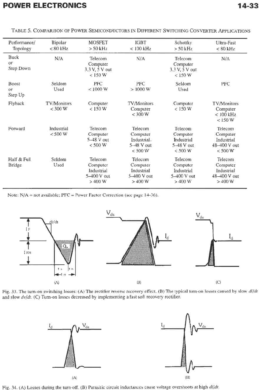
TABLE
5.
COMPARISON
OF
POWER SEMICONDUCTORS
IN
DIFFERENT
SWITCHING CQNVERTER AF'PLICATIQNS
Performance/ Bipolar
MOSFET IGBT Schottky Ultra-Fast
Topology
<
80
kHz
>
50
kHz
<
100
wz
>
50
kHz
<
80
kHz
Buck
or
Step Down
Boost
or
Step Up
Flyback
Forward
Half
&
Full
Bridge
NIA
Seldom
Used
TVIMonitors
<
300
W
Industrial
<
500
W
Seldom
Used
Telecom
Computer
3.3
v,
5
v
out
<
150
w
PFC
<
1000
W
Computer
<
150W
Telecom
Computer
5-48
V out
<
500
W
Telecom
Computer
Industrial
5400
V out
>
400 W
PFC
>
1000
w
TV/Monitors
Computer
<
300
W
Telecom
Computer
Industrial.
5-48
V out
<
500 W
Telecom
Computer
Industrial
5400
v
out
>
400 W
Telecom
Computer
3.3
v,
5
v
out
<15ow
Seldom
Used
Computer
<
150
w
Telecom
Computer
Industrial
548
V out
<
500
W
Telecom
Computer
Industrial
5-400
V out
>
400 W
PFC
TVNonitors
Computer
<
100
kHz
<
150
w
Telecom
Computer
Industrial
48400
V out
<
500
w
Telecom
Computer
Industrial
48-400
V out
>
400
W
~~
Note: N/A
=
not available; PFC =Power Factor Correction
(see
page
14-36).
(A)
(E)
(C)
Fig
33
The turn-on switching losses: (A) The rectifier reverse recovery effect. (€3) The typical turn-on
losses
caused by slow
dzldt
and slow
dv/dt
(C) Turn-on losses decreased by implementing a fast soft recovery rectifier
(A) (B)
Fig.
34.
(A) Losses during the turn-off. (E) Parasitic circuit inductances cause voltage overshoots at high
di/dt
14-34
REFERENCE
DATA
FOR ENGINEERS
A
hard
clamp is used only for reducing the level of a
voltage spike. It has no effect
on
the
dvldt
of the
transition. Therefore it is not very useful for
reducing EMI/RFI
.*
It is useful for preventing
components such as semiconductors and capaci-
tors from entering avalanche breakdown.
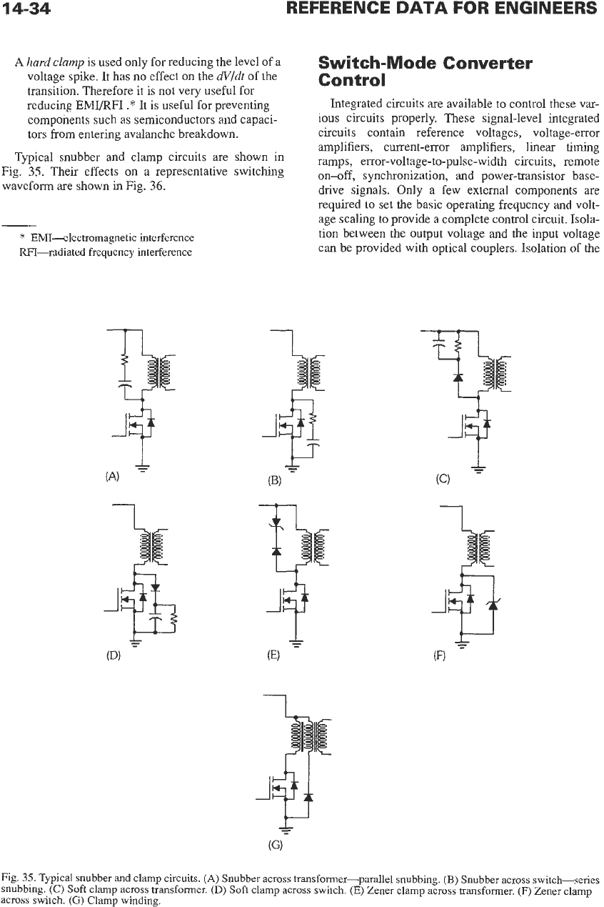
Typical snubber and clamp circuits are shown in
Fig.
35.
Their effects
on
a representative switching
waveform are shown in Fig.
36.
*
EMI-electromagnetic interference
RFI--radiated frequency interference
1
Switch-Mode
Converter
Control
Integrated circuits are available to control these var-
ious circuits properly. These signal-level integrated
circuits contain reference voltages, voltage-error
amplifiers, current-error amplifiers, linear timing
ramps, error-voltage-to-pulse-width circuits, remote
on-off,
synchronization, and power-transistor base-
drive signals. Only a few external components are
required to set the basic operating frequency and volt-
age scaling
to
provide a complete control circuit. Isola-
tion between the output voltage and the input voltage
can be provided with optical couplers. Isolation of the
1
Fig.
35.
Typical snubber and clamp circuits. (A) Snubber across transformer-parallel snubbing.
(B)
Snubber across switch-series
snubbing.
(C)
Soft
clamp across transformer.
(D)
Soft clamp across switch. (E) Zener clamp across transformer. (F) Zener clamp
across switch.
(G)
Clamp winding.
POWER ELECTRONICS
14-35
1,
nM
(w)
Fig.
36.
The
effect
of snubbers
and clamps upon a representa-
tive
switching waveform.
power-transistor base-drive signals can be accom-
plished by pulse transformers with energy-storage
capacitors to provide a reverse pulse of base current
for fast
turn-off
of the power transistor or field-effect
transistor. Refer
to
Figs.
3
1
and
32
for different drivers
for bipolar switch-mode transistors and switch-mode
power
MOSFETs.
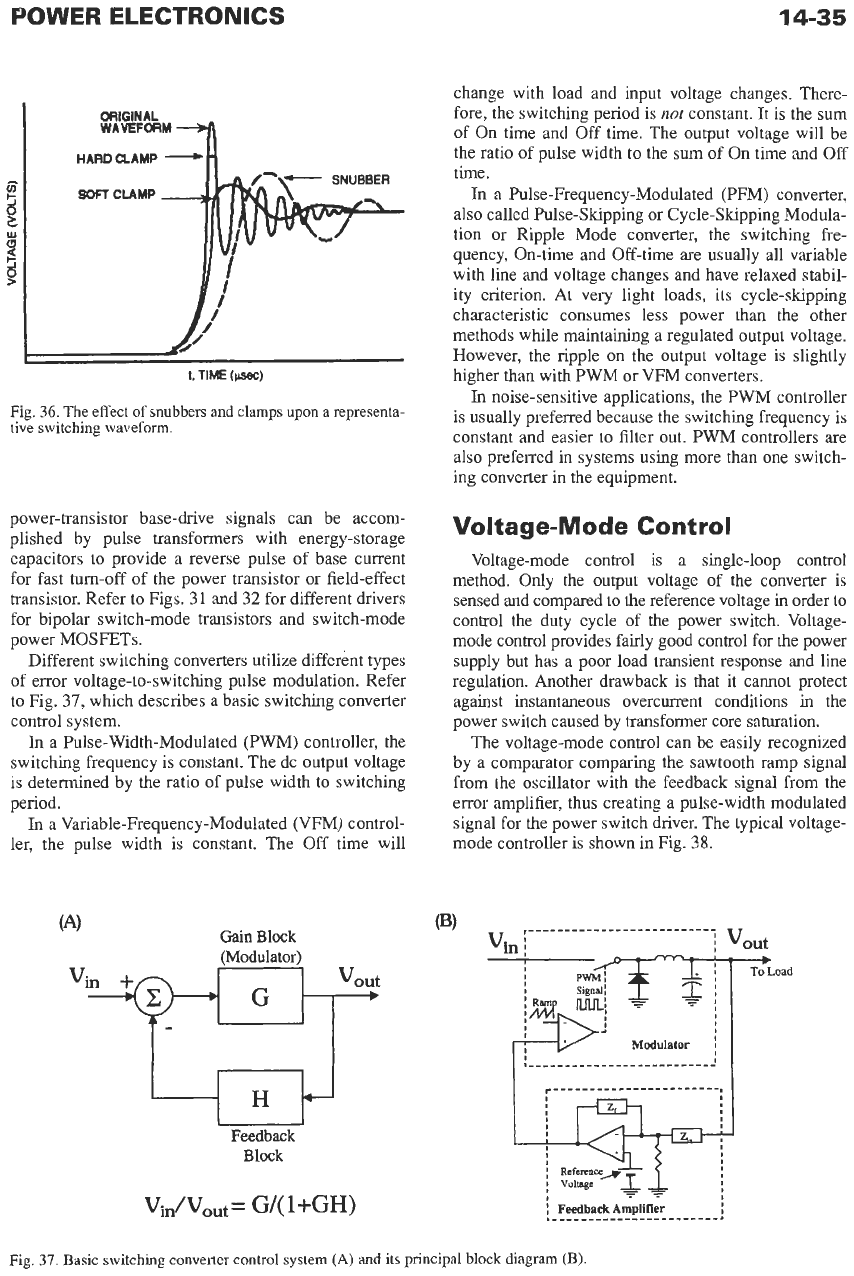
Different switching converters utilize different types
of error voltage-to-switching pulse modulation. Refer
to Fig.
37,
which describes a basic switching converter
control system.
In a Pulse-Width-Modulated (PWM) controller, the
switching frequency is constant. The dc output voltage
is
determined by the ratio of pulse width to switching
period.
In
a Variable-Frequency-Modulated (VFM) control-
ler, the pulse width is constant. The Off time will
Gain
Block
Feedback
Block
change with load and input voltage changes. There-
fore, the switching period is
not
constant.
It
is the sum
of On time and Off time. The output voltage will be
the ratio of pulse width to the sum of On time and
Off
time.
In a Pulse-Frequency-Modulated (PFM) converter,
also called Pulse-Skipping or Cycle-Skipping Modula-
tion or Ripple Mode converter, the switching fre-
quency, On-time and Off-time are usually all variable
with line and voltage changes and have relaxed stabil-
ity criterion. At very light loads, its cycle-skipping
characteristic consumes less power than the other
methods while maintaining a regulated output voltage.
However, the ripple
on
the output voltage is slightly
higher than with
PWM
or VFM converters.
In
noise-sensitive applications, the
PWM
controller
is usually preferred because the switching frequency is
constant and easier to filter out. PWM controllers are
also preferred in systems using more than one switch-
ing converter in the equipment.
Voltage-Mode
Control
Voltage-mode control is a single-loop control
method. Only the output voltage of the converter is
sensed and compared to the reference voltage
in
order to
control the duty cycle of the power switch. Voltage-
mode control provides fairly good control for the power
supply but has a poor load transient response and line
regulation. Another drawback is that it cannot protect
against instantaneous overcurrent conditions
in
the
power switch caused by transformer core saturation.
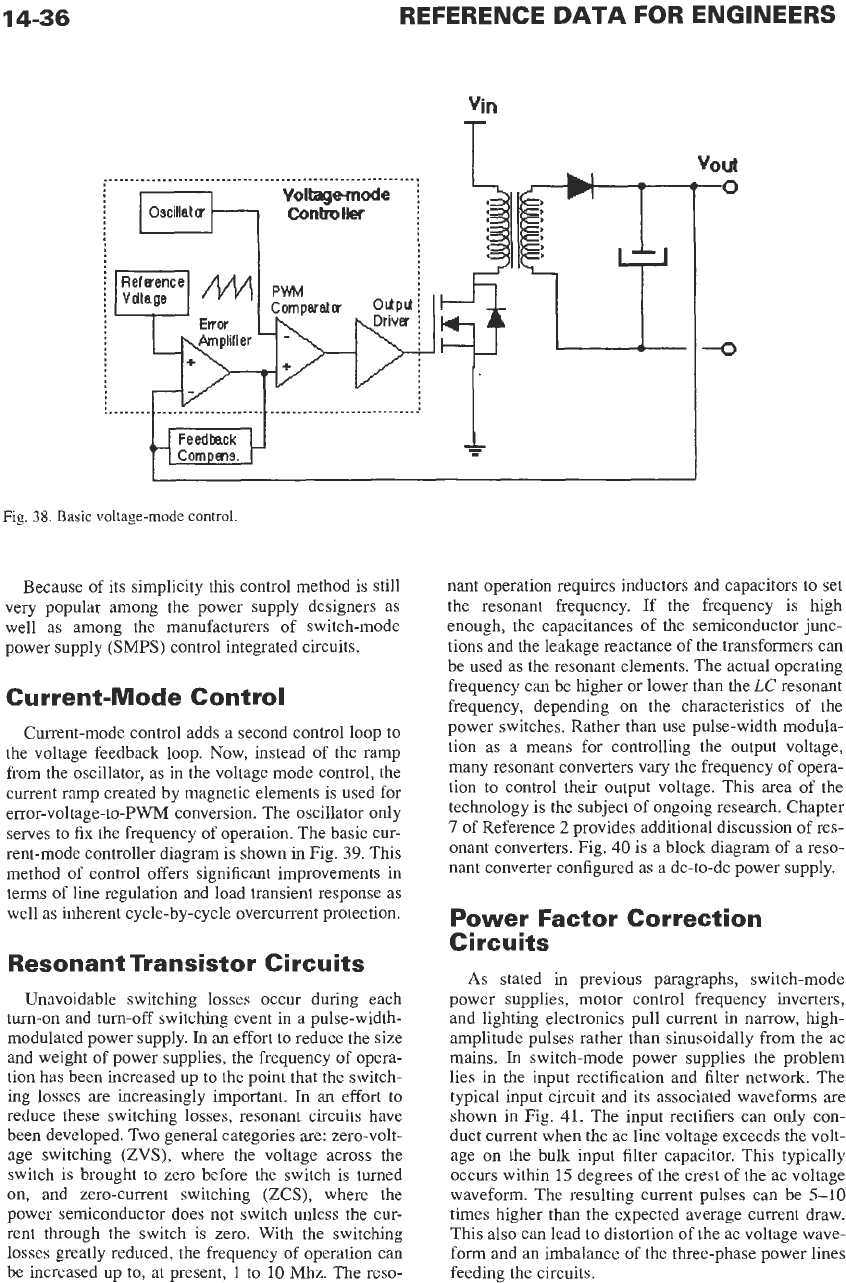
The voltage-mode control can be easily recognized
by a comparator comparing the sawtooth ramp signal
from the oscillator with the feedback signal from the
error amplifier, thus creating a pulse-width modulated
signal for the power switch driver. The typical voltage-
mode controller is shown in Fig.
38.
Vin
i
i
vout
Modulator
Fig.
37.
Basic
switching converter
control
system
(A)
and
its
principal
block
diagram
(B).
14-36
REFERENCE
DATA
FOR ENGINEERS
i"
J
d
Fig.
38.
Basic voltage-mode control.
Because of its simplicity this control method is still
very popular among the power supply designers as
well as among the manufacturers of switch-mode
power supply
(SMPS)
control integrated circuits.
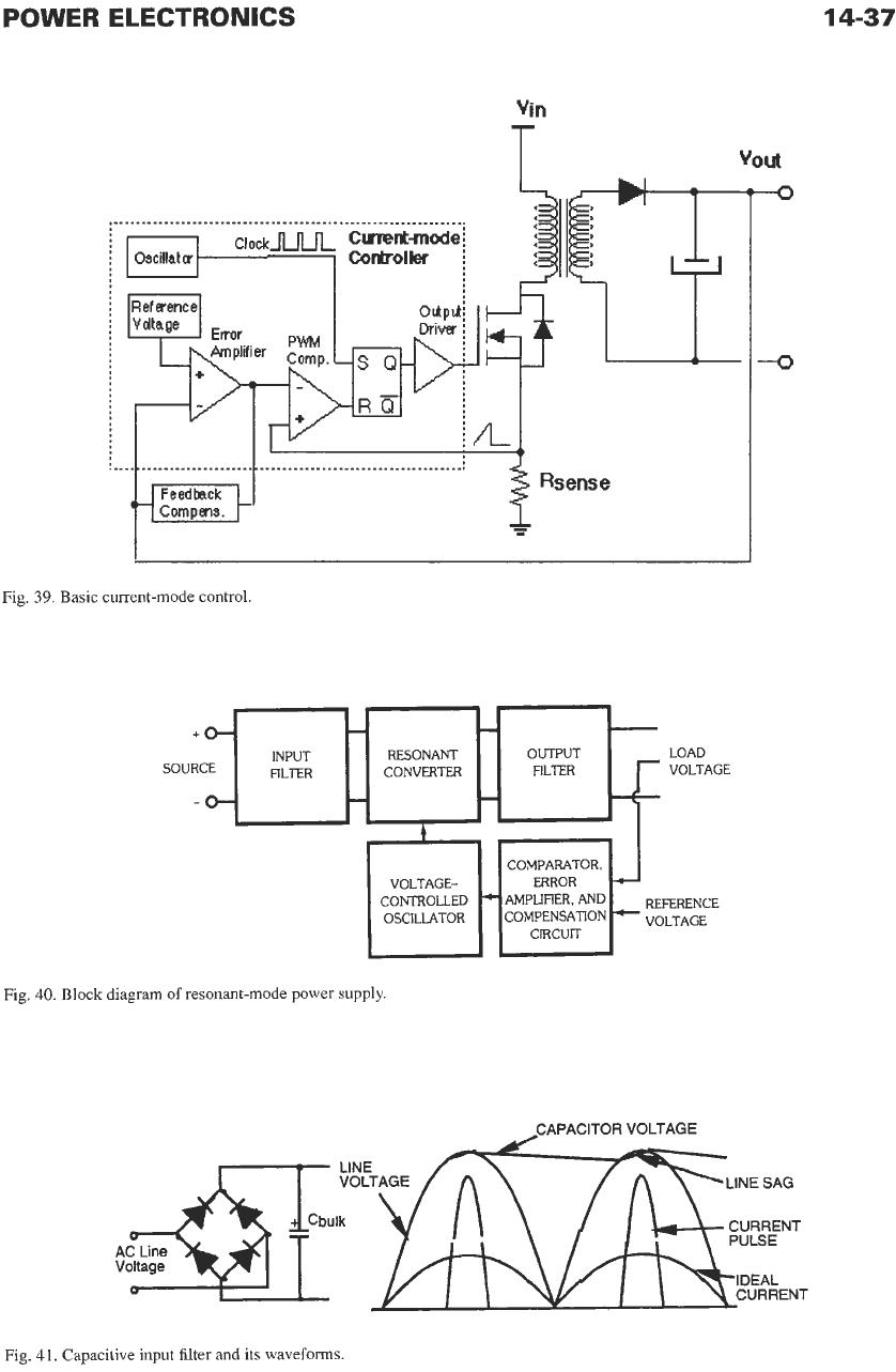
Current-Mode Control
Current-mode control adds a second control loop to
the voltage feedback loop. Now, instead of the ramp
from the oscillator, as in the voltage mode control, the
current ramp created by magnetic elements is used for
error-voltage-to-PWM conversion. The oscillator only
serves to fix the frequency of operation. The basic cur-
rent-mode controller diagram is shown in Fig.
39.
This
method of control offers significant improvements in
terms
of
line regulation and load transient response as
well as inherent cycle-by-cycle overcurrent protection.
Resonant Transistor Circuits
Unavoidable switching losses occur during each
turn-on and
turn-off
switching event in a pulse-width-
modulated power supply.
In
an effort to reduce the size
and weight of power supplies, the frequency of opera-
tion has been increased up
to
the point that the switch-
ing losses are increasingly important.
In
an effort to
reduce these switching losses, resonant circuits have
been developed. Two general categories are: zero-volt-
age switching
(ZVS),
where the voltage across the
switch is brought
to
zero before the switch is turned
on,
and zero-current switching (ZCS), where the
power semiconductor does not switch unless the cur-
rent through the switch is zero. With the switching
losses greatly reduced, the frequency of operation can
be increased up to, at present,
1
to
10
Mhz.
The reso-
YOUt
-0
--o
nant operation requires inductors and capacitors
to
set
the resonant frequency. If the frequency is high
enough, the capacitances of the semiconductor junc-
tions and the leakage reactance of the transformers can
be used as the resonant elements. The actual operating
frequency can be higher or lower than the
LC
resonant
frequency, depending
on
the characteristics of the
power switches. Rather than use pulse-width modula-
tion as a means for controlling the output voltage,
many resonant converters
vary
the frequency of opera-
tion
to
control their output voltage. This area of the
technology is the subject of ongoing research. Chapter
7
of Reference
2
provides additional discussion of res-
onant converters. Fig. 40 is a block diagram of a reso-
nant converter configured as a dc-to-dc power supply.
Power Factor Correction
Circuits
As
stated in previous paragraphs, switch-mode
power supplies, motor control frequency inverters,
and lighting electronics pull current
in
narrow, high-
amplitude pulses rather than sinusoidally from the ac
mains.
In
switch-mode power supplies the problem
lies in the input rectification and filter network. The
typical input circuit and its associated waveforms are
shown in Fig. 41. The input rectifiers can only con-
duct current when the ac line voltage exceeds the volt-
age on the bulk input filter capacitor. This typically
occurs within
15
degrees of the crest of the ac voltage
waveform. The resulting current pulses can be 5-10
times higher than the expected average current draw.
This also can lead to distortion of the ac voltage wave-
form and an imbalance of the three-phase power lines
feeding the circuits.
POWER ELECTRONICS
i”
14-37
Fig.
39.
Basic current-mode control.
+
SOUR
Fig.
40.
Block diagram of resonant-mode power supply.
-CAPACITOR
VOLTAGE
Fig.
41.
Capacitive input filter and its waveforms.
14-38
REFERENCE
DATA
FOR ENGINEERS
Power Factor Definition
Ideally the ac current provided by local utilities
should be purely sinusoidal and free of surges, tran-
sients, and electrical noise (see Fig.
42).
The power
factor
(PF)
is
defined by the ratio of the real power
PR
to the
total
apparent power
PA:
PF=- PR
(Eq.
2)
PA
The real power
PR
can be calculated
as
the average
of the instantaneous product
of
voltage and current
taken at each instance in time over the full period,
T:
(Eq.
3)
where
e
=
voltage and
i
=
current. The apparent power,
a sum of the real power and reactive power, is calcu-
lated
as
the product of the
rms
current measured over
the full period and the
rms
voltage measured over the
same full period:
=
vRMS
’
IRMS
(Eq.
4)
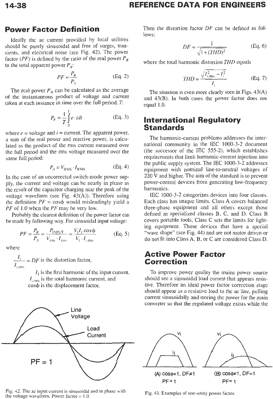
In the case of an uncorrected switch-mode power sup-
ply, the current and voltage can be nearly in phase as
the result
of
the capacitor charging near the peak of the
voltage waveform (see Fig.
43(A)).
Therefore using
the definition
PF
=
cos+ would misleadingly yield
a
PF
of
1.0
when the
PF
may be very low.
Probably the clearest definition of the power factor can
be made by following way. For sinusoidal input voltage:
where
=
DF
is the distortion factor,
Ii.rms
I,
is the first harmonic of the input current,
I;,,,
is the total harmonic current, and
cos+
is
the displacement factor.
Line
Voltage
W
Fig.
42.
The ac input current is sinusoidal
and
in phase with
the voltage waveform. Power factor
=
1.0
Then the distortion factor
DF
can be defined as fol-
lows:
(Eq.
6)
1
DF
=
2JI1+01
where the total harmonic distortion
THD
equals
(Eq.
7)
ljIITnns
-
1:
THD
=
I,
The situation is even more clearly seen
in
Figs.
43(A)
and
43(B).
In
both cases the power factor does not
equal
1.0.
In tern at iona
I
Reg
u
latory
Standards
The harmonic-current problems addresses the inter-
national community in the IEC
1000-3-2
document
(the successor of the LEC
555-2),
which establishes
requirements that limit harmonic-current injection into
the public supply system. The IEC
1000-3-2
addresses
equipment with nominal line-to-neutral voltages
of
220
V
and higher. The aim of the standard
is
to
prevent
power-control devices from generating low-frequency
harmonics.
IEC
1000-3-2
categorizes devices into
four
classes.
Each class has unique limits. Class
A
covers balanced
three-phase equipment and all others except those
defined in specialized classes
B,
C, and
D.
Class
B
covers portable tools, Class C sets the limits for light-
ing equipment. Those devices that have a special
“wave shape” (see Fig.
44)
and are not motor driven or
do not fit into Class
A, B,
or C are considered Class
D.
Active Power Factor
Correction
To improve power quality the mains power source
should see a sinusoidal load current that appears resis-
tive. Therefore an ideal power factor correction stage
should appear as a resistive load
to
the ac line, pulling
current sinusoidally and storing the power for the main
converter
so
that the regulated voltage exists while the
(A)
cosQ=l, DFF1
(B)
CosQtl,
DF=1
PFC 1 PF‘
1
Fig.
43.
Examples
of
non-unity power factor.
POWER
ELECTRONICS
14-39
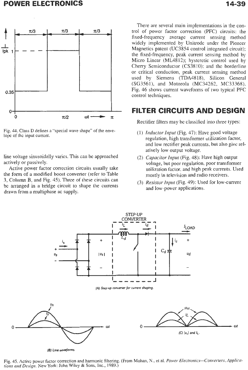
Fig.
44.
Class
D
defines
a
"special wave shape"
of
the enve-
lope
of
the input current.
line voltage sinusoidally varies.
This
can be approached
actively or passively.
Active power factor correction circuits usually take
the
form of a modified boost converter (refer to Table
3, Column
B,
and Fig. 45). Three of these circuits can
be arranged in a bridge circuit to shape the currents
drawn from a multiphase ac supply.
There are several main implementations
in
the con-
trol of power factor correction (PFC) circuits: the
fixed-frequency average current sensing method
widely implemented by Unitrode under the Pioneer
Magnetics patent (UC3854 control integrated circuit);
the fixed-frequency, peak current sensing method by
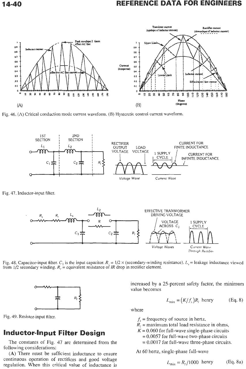
Micro Linear (ML4812); hysteretic control used by
Cherry Semiconductor (CS3810); and the borderline
or critical conduction, peak current sensing method
used by Siemens (TDA4818), Silicon General
(SG3561), and Motorola (MC34262, MC33368).
Fig. 46 shows current waveforms of two typical PFC
control techniques.
FILTER
CIRCUITS AND DESIGN
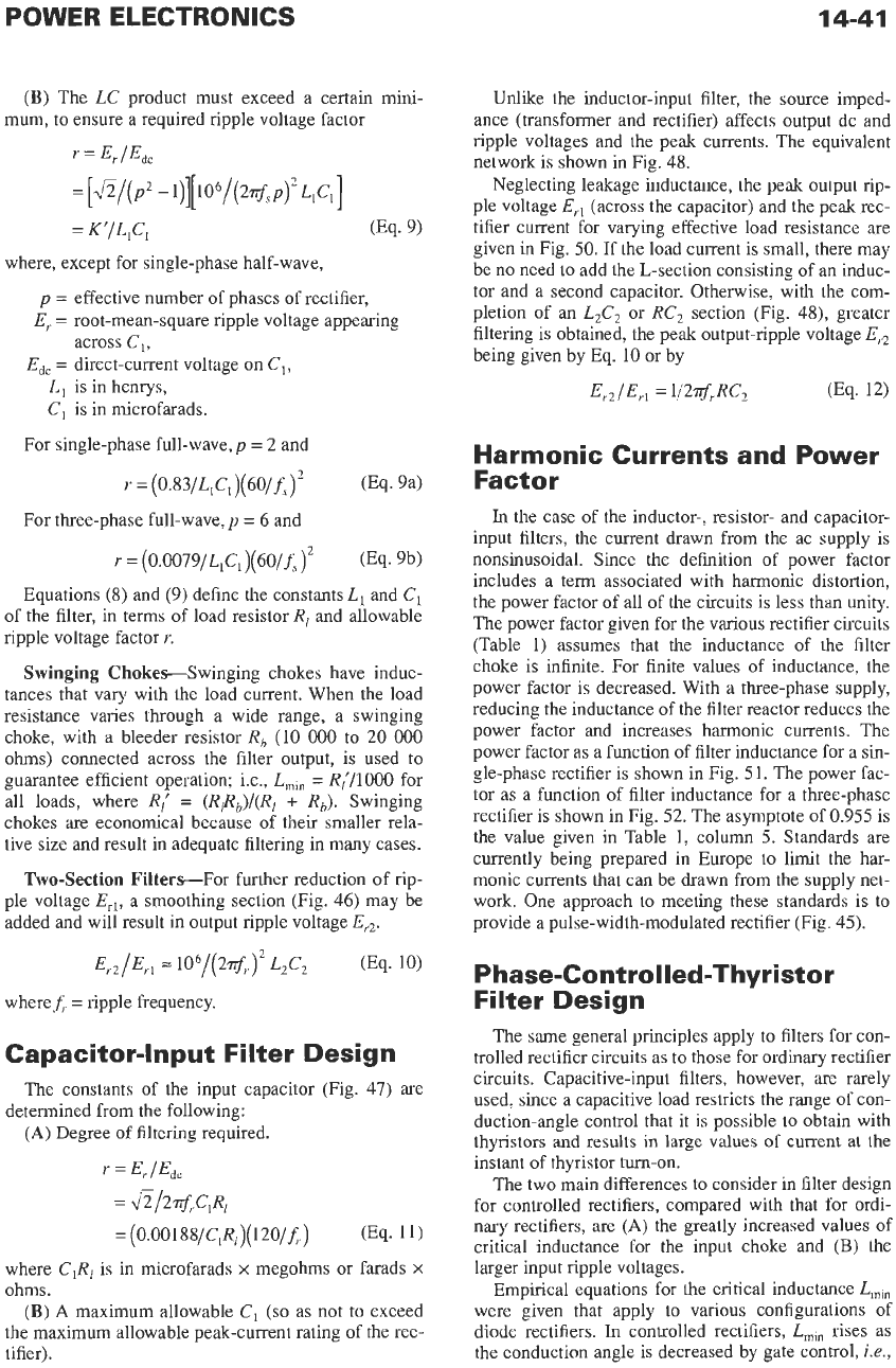
Rectifier filters may be classified into three types:
(I)
Inductor Input
(Fig. 47): Have good voltage
regulation, high transformer utilization factor,
and low rectifier peak currents, but also give rel-
atively low output voltage.
voltage, but poor regulation, poor transformer
utilization factor, and high peak currents. Used
mostly in television and radio receivers.
and low-power applications.
(2)
Capacitor Input
(Fig. 48): Have high output
(3)
Resistor Znput
(Fig. 49): Used for low-current
.--------I
(A)
Siepup
conuerter
for
current
shaplng.
0
+
wt
(6)
Llne
waveforms.
Fig.
45.
Active power factor correction and harmonic filtering.
(From
Mohan,
N..
et al.
Power Electronics-Converters,
Applica-
tions
and
Design.
New
York:
John
Wiley
&
Sons, Inc.,
1989.)
14-40
REFERENCE
DATA
FOR ENGINEERS
1
a9
ai
a1
0.6
a5
06
a3
01
a1
0
..
. . .
.
. . .
..
.
. ..
. .
..
.
.
,..
.
..
.. . .
,
oesns8s~nsq~~nq~~ea
Fig.
46.
(A)
Critical conduction mode current waveform.
(B)
Hysteretic control current waveform
1ST
1
ZND
I
SECTION SECTION
~
RECTIFIER CURRENT FOR
OUTPUT LOAD FINITE INDUCTANCE
7t&Fl
VOLTAGE
I^v"v^\
VOLTAGE
I
1
CYCLE
4
1
ITITE
CURRENT INDUCTANCE FOR
I
cl
I
c2
4
AAA
I I
I
Voltage Wove Current Wave
Fig.
47.
Inductor-input filter.
L2
EFFECTIVE TRANSFORMER
DRIVING VOLTAGE
Volfage Waues
Current
Wow
Through
Herr$ei
Fig.
48.
Capacitor-input filter.
C,
is
the
input capacitor.
R,
=
1/2
x
(secondary-winding resistance).
L,
=
leakage inductance viewed
from
1/2
secondary winding.
R,
=
equivalent resistance of
IR
drop in rectifier element.
Fig.
49,
Resistor-input filter.
Inductor-Input Filter Design
The constants of Fig.
47
are determined from the
following considerations:
(A)
There must be sufficient inductance
to
ensure
continuous operation
of
rectifiers and good voltage
regulation. When this critical value of inductance is
increased
by
a
25-percent safety factor, the
minimum
value becomes
where
f,
=
frequency
of
source in hertz,
R,
=
maximum total load resistance in ohms,
K
=
0.060
for full-wave single-phase circuits
=
0.0057
for full-wave two-phase circuits
=
0.0017
for full-wave three-phase circuits.
At
60
hertz, single-phase full-wave
L,,,
=
R,/IOOO
henry (Eq.
8a)
POWER ELECTRONICS 14-41
(B)
The
LC
product must exceed a certain mini-
mum, to ensure a required ripple voltage factor
r
=
Er
/Edc
=
K'fL,C,
(Eq.
9)
=
[&/(P*
-1)][106/(2$sP)2~,c,]
where, except for single-phase half-wave,
p
=
effective number of phases of rectifier,
E,
=
root-mean-square ripple voltage appearing
across
C,,
L,
is in henrys,
C,
is in microfarads.
E,,
=
direct-current voltage
on
C,,
For single-phase full-wave,
p
=
2
and
r
=
(0.83/L,C,)(60/fs)2
(Eq. 94
For three-phase full-wave,
p
=
6
and
r
=
(0.0079/L,C,)(60/fs)2
(Eq. 9b)
Equations
(8)
and
(9)
define the constants
L,
and
C,
of the filter, in terms of load resistor
R,
and allowable
ripple voltage factor
r.
Swinging Chokes---Swinging chokes have induc-
tances that vary with the load current. When the load
resistance varies through a wide range, a swinging
choke, with a bleeder resistor
R, (10
000
to
20
000
ohms)
connected across the filter output, is used to
guarantee efficient operation; i.e.,
Lmin
=
R,'/1000
for
all loads, where
R,'
=
(RrRb)/(Rl
+
Rb).
Swinging
chokes are economical because of their smaller rela-
tive size and result in adequate filtering in many cases.
Two-Section Filters-For further reduction of rip-
ple voltage
E,,,
a smoothing section (Fig.
46)
may be
added and will result in output ripple voltage
Er2
where
f,
=
ripple frequency.
Capacitor-Input Filter Design
The constants of the input capacitor (Fig.
47)
are
(A)
Degree
of
filtering required.
determined from the following:
r
=
E,
/E&
=
&/2$rClR,
=
(0.00188/~,R1)(~~0/~;.)
(Eq.
11)
where
C,R,
is in microfarads
x
megohms or farads
X
ohms.
(B)
A
maximum allowable
C,
(so
as not to exceed
the maximum allowable peak-current rating of the rec-
tifier).
Unlike the inductor-input filter, the source imped-
ance (transformer and rectifier) affects output dc and
ripple voltages and the peak currents. The equivalent
network is shown in Fig.
48.
Neglecting leakage inductance, the peak output rip-
ple voltage
E,,
(across the capacitor) and the peak rec-
tifier current for varying effective load resistance
are
given
in
Fig.
50.
If the load current is small, there may
be no need to add the L-section consisting of an induc-
tor and a second capacitor. Otherwise, with the com-
pletion
of
an
L2C,
or
RC,
section (Fig.
48),
greater
filtering is obtained, the peak output-ripple voltage
E,,
being given by Eq.
10
or by
E,,
/Erl
=
Y2$JG
(Eq.
12)
Harmonic Currents and Power
Factor
In
the case of the inductor-, resistor- and capacitor-
input filters, the current drawn from the ac supply is
nonsinusoidal. Since the definition of power factor
includes a term associated with harmonic distortion,
the power factor of all of the circuits is less than unity.
The power factor given for the various rectifier circuits
(Table
1)
assumes that the inductance of the filter
choke is infinite. For finite values of inductance, the
power factor is decreased. With a three-phase supply,
reducing the inductance of the filter reactor reduces the
power factor and increases harmonic currents. The
power factor as a function of filter inductance for a
sin-
gle-phase rectifier is shown in Fig.
51.
The power fac-
tor as a function of filter inductance for a three-phase
rectifier is shown in Fig.
52.
The asymptote of
0.955
is
the value given in Table
1,
column
5.
Standards are
currently being prepared in Europe to limit the har-
monic currents that can be drawn from the supply net-
work. One approach to meeting these standards is to
provide a pulse-width-modulated rectifier (Fig.
45).
Phase-Controlled-Thyristor
Filter Design
The same general principles apply to filters for con-
trolled rectifier circuits as to those for ordinary rectifier
circuits. Capacitive-input filters, however, are rarely
used, since a capacitive load restricts the range of con-
duction-angle control that it is possible to obtain with
thyristors and results
in
large
values
of
current
at
the
instant of thyristor turn-on.
The two main differences to consider in filter design
for controlled rectifiers, compared with that for ordi-
nary rectifiers, are
(A)
the greatly increased values of
critical inductance for
the
input choke and
(E)
the
larger input ripple voltages.
Empirical equations for the critical inductance
Lmin
were given that apply
to
various configurations of
diode rectifiers.
In
controlled rectifiers,
L,,,
rises as
the conduction angle is decreased by gate control,
i.e.,