Middleton W.M. (ed.) Reference Data for Engineers: Radio, Electronics, Computer and Communications
Подождите немного. Документ загружается.

Feedback
Control Systems
Revised
by
William R. Perkins"
Models of Control System Components
15-2
Error-Measuring Systems: Potentiometers, Synchros, Incremental
Encoders
DC Motors
Two-Phase Servomotors
Step Motors
Rate Generators
Stability of Linear Time-Invariant Systems
Tracking Accuracy
Disturbance Inputs
Sensitivity and Robustness
Methods of Controller Design: Classical Design
State Space Analysis and Design Techniques
Controller Design: Pole Placement
Controller Design: LQ-Optimal Control
The z-Transform
The z-Transfer Function
The Inverse z-Transform
State Variable Analysis of Digital Control Systems
Stability
of
Linear Time-Invariant Digital Systems
State Variable Design Methods: The Digital Case
System Performance
15-4
15-12
Digital Control Systems
15-15
Phase-Locked Loop Servo Systems
15-21
Nonlinear Systems
15-22
Characteristics of Nonlinear Systems
Describing-Function Technique
Phase-Plane Method
Computer-Aided Analysis and Design
15-33
Bibliography
15-33
-
*
This revision draws heavily upon the previous version
of
this chapter prepared by
B.
C.
Kuo.
15-1
15-2
REFERENCE DATA FOR ENGINEERS
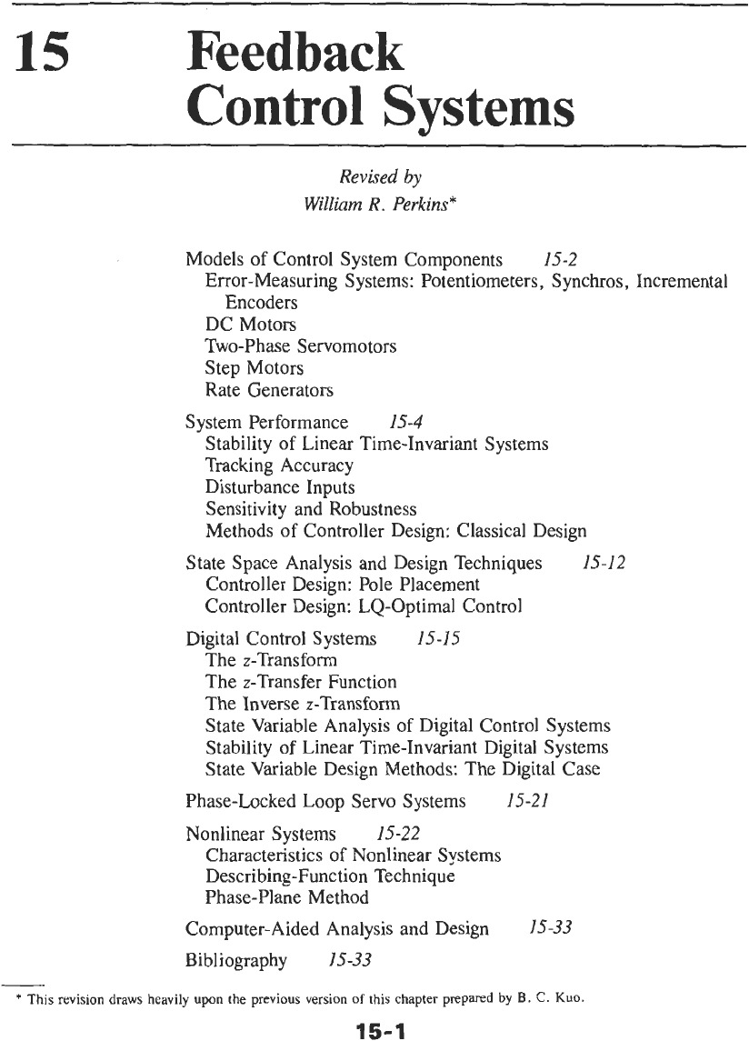
Control
is the use of feedback to achieve desired
response of dynamic systems in the presence of uncer-
tainties, disturbances, and constraints. Control systems
are found widely in many processes and products, and
include industrial and chemical process control; vehi-
cle, aircraft, and spacecraft control; automation and
manufacturing systems; and robotics, to name only a
few. Even some issues in economic and social systems
can be approached from the control system viewpoint.
And feedback control systems exist naturally in many
living systems, such as blood-pressure regulation and
heart-rate control. Fig.
1
gives a simple block-diagram
representation of a controlled process. For example, in a
motor-speed control problem, the controlled process is
the motor, the actuating signal is the voltage or current
input to the motor, and the output in this case is the
motor speed. The controlled process is called the
“plant.” Load disturbances may be present. The objec-
tive, then, is to produce a control input that causes
the controlled output to respond in a desired manner, in
the presence of disturbance inputs and uncertainties
in the plant description.
A
typical closed-loop (feedback) control system
structure is shown in Fig.
2.
In this system, the output is
measured with sensors and is “fed back” to the
controller. The controller generates an input to the
actuator, which provides an actuating input to the plant.
An actuator is needed in many systems because the
controller signal cannot drive the plant directly. For
example, consider an antenna position control system,
in which the antenna is driven by a motor, which is the
actuator for this case.
MODELS
OF
CONTROL
SYSTEM COMPONENTS
For system analysis and design, the plant, sensors,
actuators, and controllers must be modeled appropriate-
ly. Differential equations or transfer functions are
frequently used as models. For digital (computer)
control, the controller may be modeled by difference
equations.
As
examples, we consider several compo-
nents found frequently in electromechanical control
systems.
Error- Measuring Systems:
Potentiometers,
Synchros, Incremental
Encoders
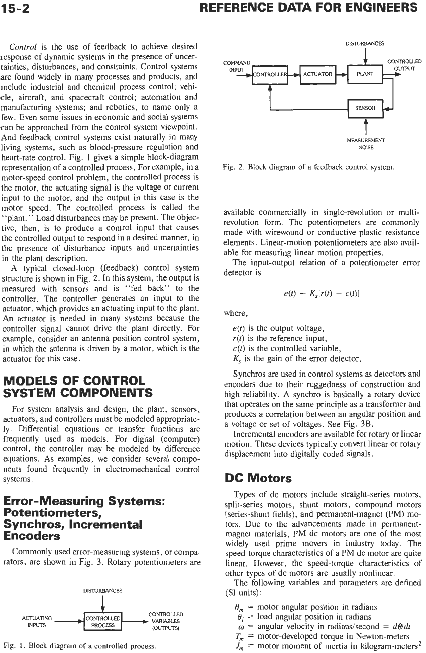
Commonly used error-measuring systems, or compa-
rators, are shown in Fig.
3.
Rotary potentiometers are
DISTURBANCES
CONTROLLED
(OVTPUTSI
ACTUATING
CONTROLLED
INPUTS
PROCESS
Fig.
1.
Block diagram
of
a controlled process.
DISTURBANCES
1
CONTROLLED
COMMAND
t
MEASUREMENT
NOISE
Fig.
2.
Biock diagram
of
a feedback control
system.
available commercially in single-revolution or multi-
revolution form. The potentiometers are commonly
made with wirewound or conductive plastic resistance
elements. Linear-motion potentiometers are also avail-
able for measuring linear motion properties.
The input-output relation of a potentiometer error
detector is
4)
=
W(t)
-
c@)l
where,
e@)
is the output voltage,
r(t)
is the reference input,
c(t)
is the controlled variable,
K,
is the gain of the error detector,
Synchros are used in control systems as detectors and
encoders due to their ruggedness of construction and
high reliability. A synchro is basically a rotary device
that operates on the same principle as a transformer and
produces a correlation between an angular position and
a voltage
or
set of voltages. See Fig.
3B.
Incremental encoders are available for rotary or linear
motion. These devices typically convert linear or rotary
displacement into digitally coded signals.
DC Motors
Types
of
dc motors include straight-series motors,
split-series motors, shunt motors, compound motors
(series-shunt fields), and permanent-magnet (PM) mo-
tors. Due to the advancements made in permanent-
magnet materials,
PM
dc motors are one
of
the most
widely used prime movers in industry today. The
speed-torque characteristics of a
PM
dc motor are quite
linear. However, the speed-torque characteristics of
other types of dc motors are usually nonlinear.
The following variables and parameters are defined
(SI
units):
Om
=
motor angular position in radians
O1
=
load angular position in radians
o
=
angular velocity in radiandsecond
=
dO/dt
Tm
=
motor-developed torque in Newton-meters
Jm
=
motor moment of inertia in kilogram-meters*
FEEDBACK
CONTROL
SYSTEMS
15-3
CONTROLLED
Cill
REFERENCE
rfti
INPUT
-----
B,,
=
viscous-friction coefficient reflected to
J,,
=
inertia reflected to motor shaft
=
‘K,
+
R,
=
armature resistance of motor in ohms
L,
=
armature inductance of motor in henrys
The transfer function between the motor displace-
motor shaft
=
B,
+
N2B,
N~J,
ment and input voltage is
B,(s)/E,(s)
=
K,/{s[L,J,,s~
+
(RJ,,
+
B,,L,)s
+
(KbKm
+
RaBrne)]}
REFERENCE
INPUT
rlt)
CONTROLLED,
VARIABLE
cltl
(A)
Potentlometer
systems
SYNCHRO SYNCHRO CONTROL
GENERATOR TRANSFORMER
cx
c,
SI
SI
F
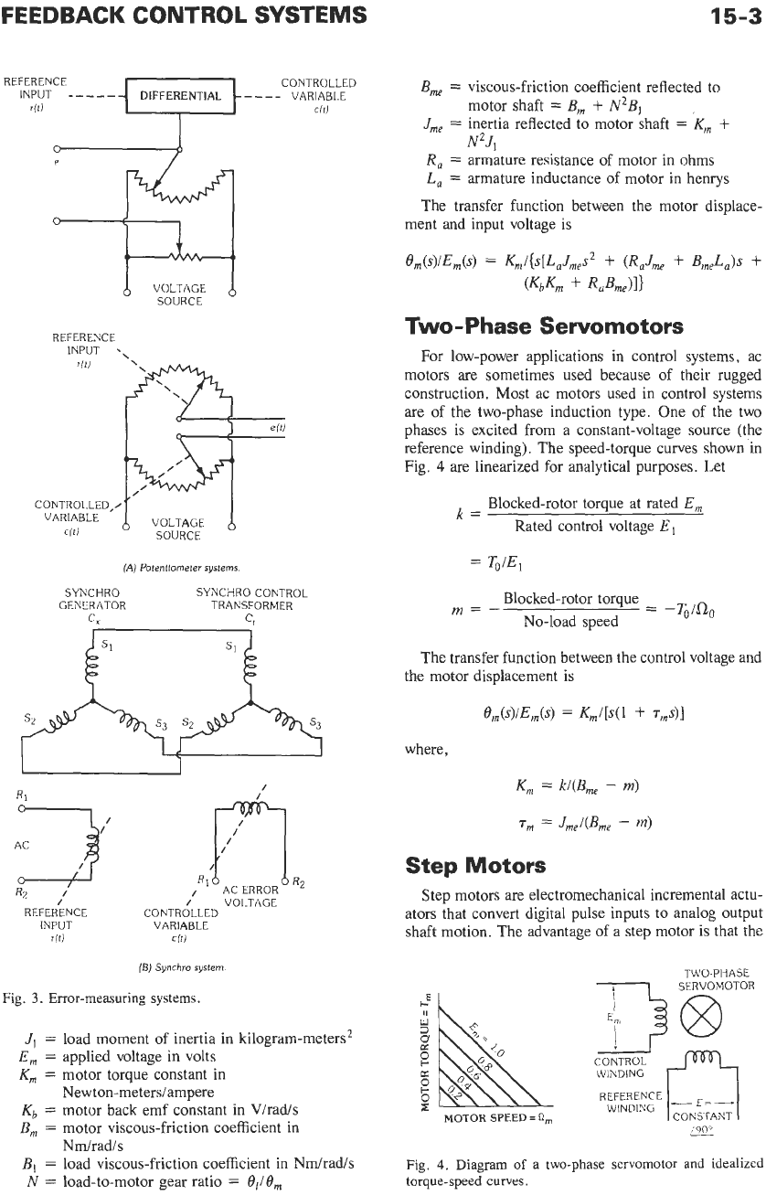
Two-Phase Servomotors
For low-power applications in control systems, ac
motors are sometimes used because of their rugged
construction. Most ac motors used in control systems
are of the two-phase induction type. One of the two
phases is excited from a constant-voltage source (the
reference winding). The speed-torque curves shown in
Fig.
4
are linearized for analytical purposes. Let
Blocked-rotor torque at rated
E,
Rated control voltage
El
k=
=
To/E,
Blocked-rotor torque
No-load speed
m=-
=
-T&j
The transfer function between the control voltage and
the motor displacement is
where,
R1
R2
,I
REFERENCE
INPUT VARIABLE
rili
cfti
(B)
Synchro system.
Fig.
3.
Error-measuring systems.
/
J,
=
load moment of inertia in kilogram-meters2
E,
=
applied voltage in volts
K,
=
motor torque constant in
New ton-metersiampere
Kb
=
motor back emf constant in V/rad/s
B,
=
motor viscous-friction coefficient in
B,
=
load viscous-friction coefficient in Ndradis
N
=
load-to-motor gear ratio
=
BJB,
Ndradis
K,
=
k/(B,,
-
m)
T,
=
JmABm,
-
m)
Step Motors
Step motors are electromechanical incremental actu-
ators that convert digital pulse inputs to analog output
shaft motion. The advantage of a step motor is that
the
TWO-PHASE
1
SERVOMOTOR
WINDING
Fig.
4.
Diagram
of
a
two-phase servomotor and idealized
torque-speed curves.
15-4
REFERENCE DATA FOR ENGINEERS
PHASE A
+
p
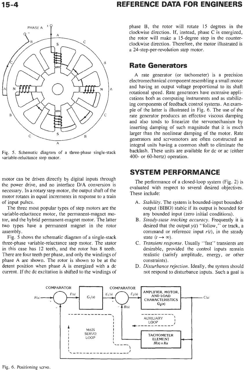
Fig.
5.
Schematic diagram
of
a
three-phase single-stack
variable-reluctance
step
motor.
motor can be driven directly by digital inputs through
the power drive, and
no
interface
D/A
conversion is
necessary. In a rotary step motor, the output shaft of the
motor rotates in equal increments in response to a train
of input pulses.
The three most popular types
of
step motors are the
variable-reluctance motor, the permanent-magnet mo-
tor, and the hybrid permanent-magnet motor. The latter
two types have a permanent magnet in the rotor
assembly.
Fig.
5
shows the schematic diagram of a single-stack
three-phase variable-reluctance step motor. The stator
in this case has
12
teeth, and the rotor has
8
teeth.
There are four teeth per phase, and only the windings of
phase
A
are shown. The rotor is shown to be at the
detent position when phase
A
is energized with a dc
current. If the dc excitation is shifted to the windings of
phase
B,
the rotor will rotate 15 degrees in the
clockwise direction. If, instead, phase
C
is energized,
the rotor will make a 15-degree step in the counter-
clockwise direction. Therefore, the motor illustrated is
a 24-step-per-revolution step motor.
Rate Generators
A
rate generator (or tachometer) is a precision
electromechanical component resembling a small motor
and having an output voltage proportional to its shaft
rotational speed. Rate generators have extensive appli-
cations both as computing instruments and as stabiliz-
ing components of feedback control systems.
An
exam-
ple of the latter is illustrated in Fig.
6.
The use of the
rate generator produces an effective viscous damping
and also tends to linearize the servomechanism by
inserting damping of such magnitude that it is much
larger than the nonlinear damping of the motor. Rate
generators and servomotors are often constructed as
integral units having a common shaft to eliminate the
backlash. These units are available for dc or ac (either
400- or 60-hertz) operation.
SYSTEM PERFORMANCE
The performance of a closed-loop system (Fig.
2)
is
evaluated with respect to several desired objectives.
These include:
A.
B.
C.
D.
Stability.
The system is bounded-input bounded-
output
(BIBO)
stable if its output is bounded for
any bounded input (zero initial conditions).
Steady-state tracking accuracy.
Frequently it
is
desired that the output
y(t)
“follow,” or track, a
command or reference input
r(t),
in the steady
state
(t
+
00).
Transient response.
Usually “fast” transients are
desirable, provided the control inputs remain
realistic (satisfy amplitude, energy, or other
constraints).
Disturbance rejection.
Ideally, the system should
not respond to disturbance inputs. Such a goal is
COMPARATOR
-I
COMPARATOR
-
AMPLIFIER. MOTOR,
AND LOAD
CHARACTERISTICS
GzW
C(Sl
E2(S)
Gllsl
Fig.
6.
Positioning servo.
FEEDBACK
CONTROL
SYSTEMS
15-5
E.
unrealistic, and small (or zero) steady-state ef-
fects are sought, following rapid transients.
Sensitivity
and
robustness.
The system should
perform well in the presence of uncertain plant
models. Such modeling inaccuracies are always
present, and a central purpose of feedback is to
obtain satisfactory performance in the presence
of such inaccuracies and uncertainties.
We consider each of these objectives in detail.
Stability
of
Linear
Time-Invariant
Systems
A
linear time-invariant system is BIBO stable if and
only if all roots of the characteristic equation lie strictly
in the left-half s-phase. The location of these roots can
be determined directly by finding the roots numerically
(with computer assistance, if necessary),
if
all system
parameter values are known. Several other methods are
available for investigating stability. These methods also
provide additional information concerning system per-
formance that is useful in both analysis and design. We
outline here the following methods:
1.
Routh-Hurwitz criterion
2.
Nyquist criterion
3.
Root locus diagram
4.
Bode diagram
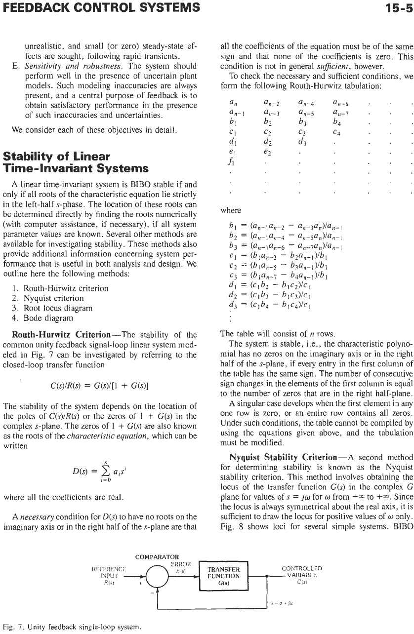
Routh-Hurwitz Criterion-The stability of the
common unity feedback signal-loop linear system mod-
eled in Fig.
7
can be investigated by referring to the
closed-loop transfer function
C(s)/R(s)
=
G(s)/[l
+
G(s)]
The stability of the system depends on the location of
the poles of
C(s)/R(s)
or the zeros of
1
+
G(s)
in the
complex s-plane. The zeros of
1
+
G(s)
are also known
as the roots of the
characteristic equation,
which can be
written
n
D(s)
=
aisl
i=o
where all the coefficients are real.
A
necessary
condition for
D(s)
to
have no roots on the
imaginary axis or in the right half
of
the s-plane are that
all the coefficients of the equation must be of the same
sign and that none
of
the coefficients is zero. This
condition is not in general su$cient, however.
To check the necessary and sufficient conditions, we
form the following Routh-Hurwitz tabulation:
an
an-2
an-4
an-6
.
an-1
an-3
an-5
an-7
.
CI
c2
c3
e4
el
e2
bl
b?
b3
b4
dl
d2
d3
fl
The table will consist of
n
rows.
The system is stable, i.e., the characteristic polyno-
mial has no zeros on the imaginary axis or in the right
half of the s-plane, if every entry in the first column of
the table has the same sign. The number of consecutive
sign changes in the elements of the first column is equal
to the number of zeros that are in the right half-plane.
A
singular case develops when the first element in any
one row is zero, or an entire row contains all zeros.
Under such conditions, the table cannot be compiled by
using the equations given above, and the tabulation
must be modified.
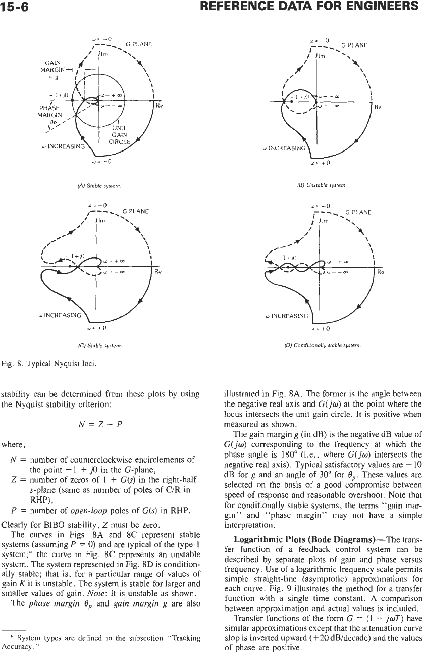
Nyquist Stability Criterion-A second method
for determining stability is known as the Nyquist
stability criterion. This method involves obtaining the
locus of the transfer function
G(s)
in the complex
G
plane for values of
s
=
jw
for
o
from
--CC
to
+m.
Since
the locus is always symmetrical about the real axis, it is
sufficient to draw the locus for positive values of
w
only.
Fig.
8
shows loci for several simple systems. BIBO
COMPARATOR
CONTROLLED
C(Si
ERROR
REFERENCE
INPUT
7
EM
4-1
FUNCTION
VARIABLE
R(s1
S=O+JO
COMPARATOR
CONTROLLED
C(Si
ERROR
REFERENCE
INPUT
7
EM
4-1
FUNCTION
VARIABLE
R(s1
S=O+JO
Fig.
7.
Unity
feedback
single-loop
system
15-6
/
,#’
I
REFERENCE
DATA
FOR
ENGINEERS
\
\
\
I
I
+
m
w=
+o
d’
,-(
<.-x-,/D
(A)
Stoble
system
\
\
\
\
w-
+
m
I
w-+m
o
INCREASING
w-
+O
(C)
Stable
system.
Fig.
8.
Typical
Nyquist
loci.
stability can be determined from these plots by using
the Nyquist stability criterion:
N=Z-P
where,
N
=
number of counterclockwise encirclements of
Z
=
number of zeros of
1
+
G(s)
in the right-half
the point
-1
+
j0
in the G-plane,
s-plane (same as number of poles of
C/R
in
RW,
P
=
number of
open-loop
poles of
G(s)
in
RHP.
Clearly for BIB0 stability,
2
must be zero.
The curves in Figs.
8A
and 8C represent stable
systems (assuming
P
=
0)
and are typical of the type-1
system;* the curve in Fig.
8C
represents an unstable
system. The system represented in Fig.
8D
is condition-
ally stable; that
is,
for a particular range of values
of
gain Kit is unstable. The system is stable for larger and
smaller values of gain.
Note:
It
is
unstable as shown.
The
phase margin
eP
and
gain margin
g
are also
*
System
types
are
defined
in
the
subsection “Tracking
Accuracy.
”
illustrated in Fig.
8A.
The former is the angle between
the negative real axis and
G(jw)
at the point where the
locus intersects the unit-gain circle. It
is
positive when
measured as shown.
The gain margin
g
(in dB) is the negative dB value of
G(
jo)
corresponding to the frequency at which the
phase angle is 180” (i.e., where
G(jw)
intersects the
negative real axis). Typical satisfactory values are
-
10
dB for
g
and an angle of
30”
for
4,.
These values are
selected on the basis of a good compromise between
speed
of
response and reasonable overshoot. Note that
for conditionally stable systems, the terms “gain mar-
gin” and “phase margin” may not have a simple
interpretation.
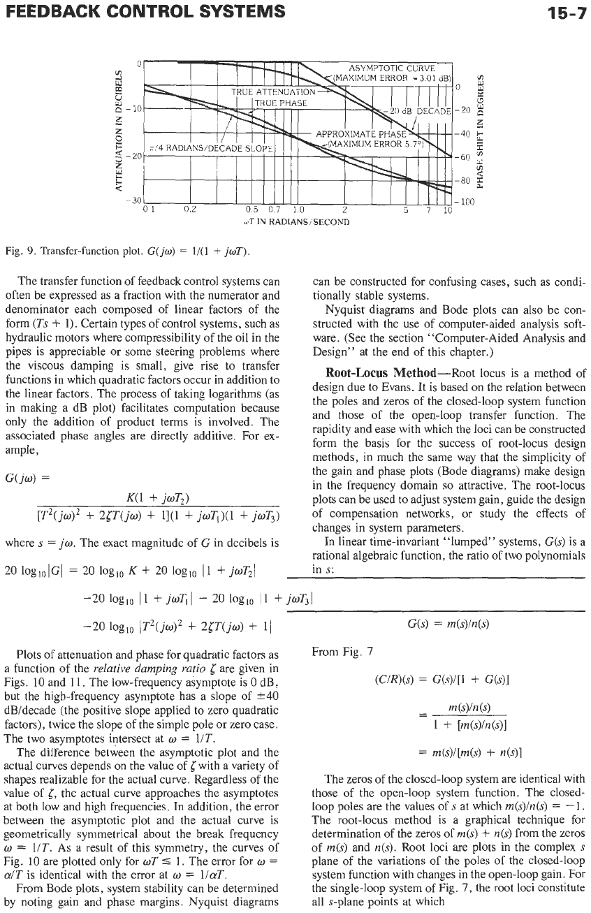
Logarithmic Plots
(Bode
Diagrams)-The trans-
fer function of a feedback control system can be
described by separate plots
of
gain and phase versus
frequency. Use of a logarithmic frequency scale permits
simple straight-line (asymptotic) approximations for
each curve. Fig.
9
illustrates the method for a transfer
function with a single time constant.
A
comparison
between approximation and actual values is included.
Transfer functions of the form
G
=
(1
+
joT)
have
similar approximations except that the attenuation curve
slop is inverted upward
(+20
dB/decade) and the values
of phase are positive.
FEEDBACK
CONTROL
SYSTEMS
15-7
01
02
05
07
10
2
5
7
10
yiT
IN
RADlANSiSECOND
Fig.
9.
Transfer-function plot.
G(jw)
=
l/(l
+
jdf).
The transfer function of feedback control systems can
often be expressed as a fraction with the numerator and
denominator each composed of linear factors of the
form
(Ts
+
1).
Certain types
of
control systems, such as
hydraulic motors where compressibility of the oil in the
pipes is appreciable or some steering problems where
the viscous damping is small, give rise to transfer
functions in which quadratic factors occur in addition to
the linear factors. The process of taking logarithms (as
in making a dB plot) facilitates computation because
only the addition of product terms is involved. The
associated phase angles are directly additive. For ex-
ample,
C(jw)
=
K(l
+
ioT)
[T2(jwl2
+
25~(jw)
+
11(1
+
jw~,)(1
+
joT3)
where
s
=
jo.
The exact magnitude of
G
in decibels is
20
logl0lGI
=
20
loglo
K
+
20
loglo 11
+
jwT2\
can be constructed for confusing cases, such as condi-
tionally stable systems.
Nyquist diagrams and Bode plots can also be con-
structed with the use of computer-aided analysis soft-
ware. (See the section “Computer-Aided Analysis and
Design” at the end of this chapter.)
Root-Locus Method-Root locus is a method of
design due
to
Evans. It is based on the relation between
the poles and zeros of the closed-loop system function
and those of the open-loop transfer function. The
rapidity and ease with which the loci can be constructed
form the basis for the success of root-locus design
methods, in much the same way that the simplicity of
the gain and phase plots (Bode diagrams) make design
in the frequency domain
so
attractive. The root-locus
plots can be used to adjust system gain, guide the design
of compensation networks, or study the effects of
changes in system parameters.
In linear time-invariant “lumped” systems,
C(s)
is a
rational algebraic function, the ratio of two polynomials
-20
loglo 11
+
jwT,
I
-
20
loglo 11
+
jwT.1
-20
loglo
1T2(jw)*
+
24‘T(jw)
+
11
G(s)
=
m(s)/n(s)
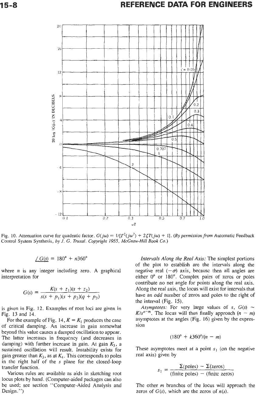
Plots of attenuation and phase for quadratic factors as
a function of the
relative damping ratio
5
are given in
Figs. 10 and 11. The low-frequency asymptote is
0
dB,
but the high-frequency asymptote has a slope of
k40
dBldecade (the positive slope applied to zero quadratic
factors), twice the slope of the simple pole or zero case.
The two asymptotes intersect at
w
=
UT.
The difference between the asymptotic plot and the
actual curves depends
on
the value of with a variety of
shapes realizable for the actual curve. Regardless of the
value of
{,
the actual curve approaches the asymptotes
at both low and high frequencies. In addition, the error
between the asymptotic plot and the actual curve
is
geometrically symmetrical about the break frequency
w
=
UT.
As
a result of this symmetry, the curves of
Fig. 10 are plotted only for
wT
5
1.
The error for
w
=
a/T
is identical with the error at
w
=
l/aT.
From Bode plots, system stability can be determined
by noting gain and phase margins. Nyquist diagrams
From Fig.
7
(C/R)(S)
=
G(s)/[l
+
G(s)]
-
m
(s)
-
1
+
[m(s)M)l
=
rn(s)/[rn(s)
+
n(s)]
The zeros of the closed-loop system are identical with
those of the open-loop system function. The closed-
loop poles are the values of
s
at which
m(s)/n(s)
=
-
1.
The root-locus method
is
a graphical technique for
determination of the zeros
of
m(s)
+
n(s)
from the zeros
of
m(s)
and
n(s).
Root loci are plots in the complex
s
plane of the variations
of
the poles of the closed-loop
system function with changes in the open-loop gain. For
the single-loop system
of
Fig.
7,
the root loci constitute
all s-plane points at which
15-8
REFERENCE
DATA
FOR
ENGINEERS
Fig.
10.
Attenuation curve
for
quadratic factor.
G(jo)
=
li[T2(jo2)
-F
2cT(jo)
+
I].
(By permissionfrom
Automatic Feedback
Control System Synthesis,
by
J.
G.
Truxal. Copyright
1955,
McGraw-Hill
Book
Cu.)
=
180"
+
n360"
where
n
is any integer including zero. A graphical
interpretation for
G(s)
=
K(s
+
Zd(S
+
22)
4s
+
PI)@
+
P2h
+
P3)
is
given in Fig.
12.
Examples
of
root
loci are given in
Fig.
13
and 14.
For the example
of
Fig. 14,
K
=
Kl
produces the case
of critical damping. An increase in gain somewhat
beyond this value causes a damped oscillation to appear.
The latter increases in frequency (and decreases in
damping) with further increase in gain. At gain
K3,
a
sustained oscillation will result. Instability exists for
gain greater than
K3,
as at
K4.
This corresponds to poles
in the right half
of
the
s
plane for the closed-loop
transfer function.
Various rules are available as aids in sketching root
locus plots by hand. (Computer-aided packages can also
be used; see section "Computer-Aided Analysis and
Design.")
Intervals Along the
Real
Axis:
The simplest portions
of the plot to establish are the intervals along the
negative real
(-cr)
axis, because then all angles are
either
0"
or
180".
Complex pairs
of
zeros or poles
contribute no net angle for points along the real axis.
Along the real axis, the locus will exist for intervals that
have an
odd
number
of
zeros and poles to the right
of
the interval (Fig. 15).
Asymptotes:
For
very
large values
of
s,
G(s)
-
K/Frn.
The locus will thus finally approach
(n
-
m)
asymptotes at the angles (Fig.
16)
given by the expres-
sion
(180"
+
k360°/(n
-
m)
These asymptotes meet at
a
point
s,
(on
the negative
real axis) given by
Z(po1es)
-
C(zeros)
(finite poles)
-
(finite zeros)
s,
=
The other
m
branches of the locus will approach the
zeros of
G(s),
which are the zeros
of
n(s).
FEEDBACK CONTROL
SYSTEMS
15-9
dJ
Fig.
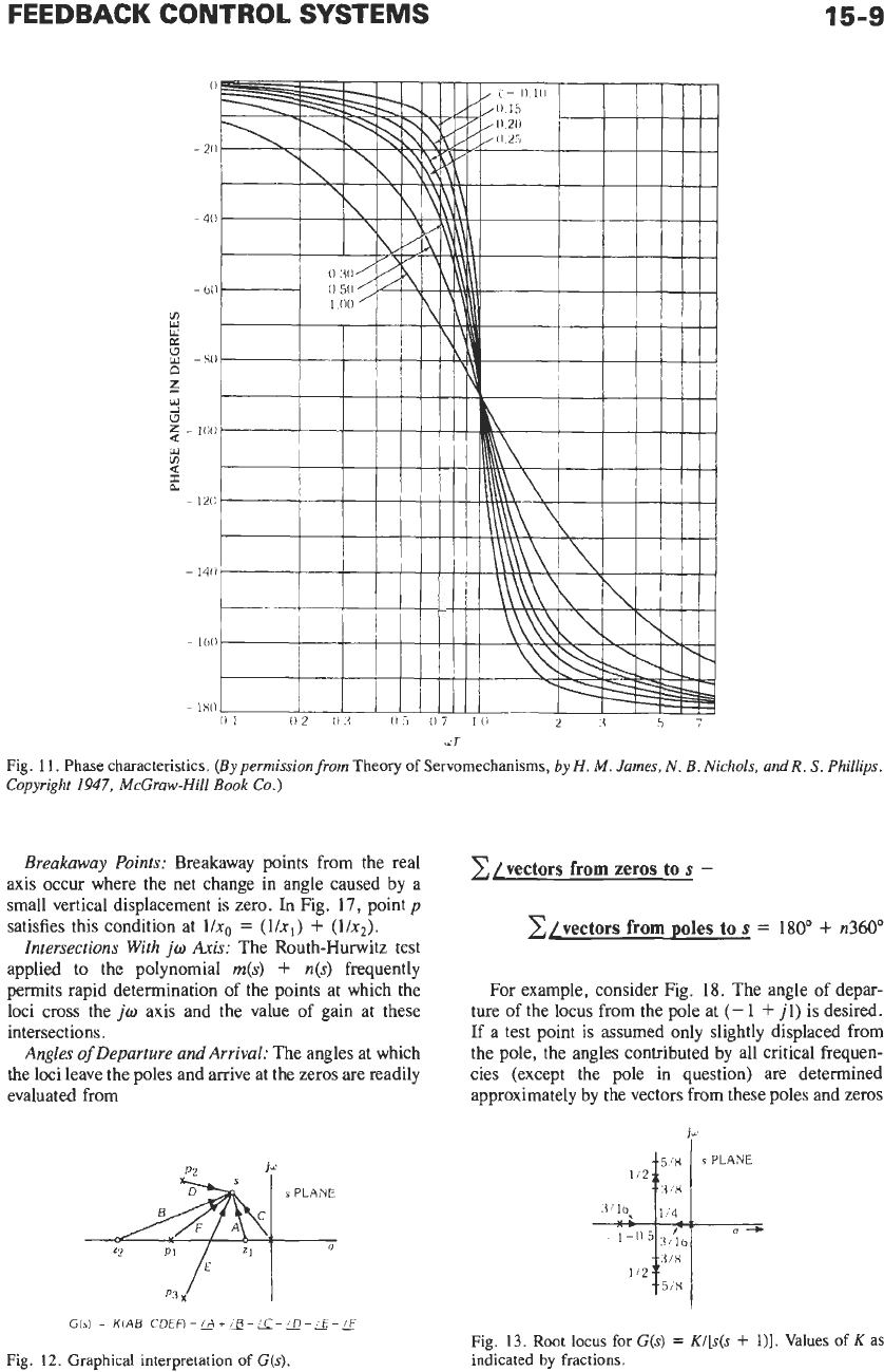
11.
Phase characteristics.
(Bypermissionfrom
Theory
of Servomechanisms,
by
H.
M.
James,
N.
B.
Nichols,
and
R.
S.
Phillips.
Copyright
1947,
McGraw-Hill
Book
Co.)
Breakaway Points:
Breakaway points from the real
axis occur where the net change in angle caused by a
small vertical displacement is zero.
In
Fig.
17,
point
p
satisfies this condition at
l/xo
=
(l/x,)
+
(l/n2).
Intersections With
jo
Axis:
The Routh-Hurwitz test
applied to the polynomial
m(s)
+
n(s)
frequently
permits rapid determination of the points at which the
loci cross the
jo
axis and the value of gain at these
intersections.
Angles
of
Departure and
Arrival:
The angles at which
the loci leave the poles and arrive at the zeros are readily
evaluated from
G(s)
=
K(A6
CDEn=&+E-c-D-&-E
Fig.
12.
Graphical interpretation of
G(s).
z/vectors
from
zeros
to
s
-
x/vectors
from
poles
to
s
=
180"
+
n360"
For example, consider Fig.
18.
The angle of depar-
ture of the locus from the pole at
(-
1
+
jl)
is desired.
If a test point
is
assumed only slightly displaced
from
the pole, the angles contributed by all critical frequen-
cies (except the pole in question) are determined
approximately by the vectors from these poles and zeros
Fig.
13.
Root locus for
G(s)
=
K/[s(s
+
l)].
Values of
K
as
indicated
by
fractions.