Middleton W.M. (ed.) Reference Data for Engineers: Radio, Electronics, Computer and Communications
Подождите немного. Документ загружается.

16-36
REFERENCE
DATA
FOR
ENGINEERS
/
i
P~LE
\
PIECE ANODE
I
OUTPUT CATHODE
(A) Overall
cross
sectton.
AXIAL DISTRIBUTION
OF
FIELD MAGNITUDES
(B)
Anode detoil.
ICJ
Coutty
detoils.
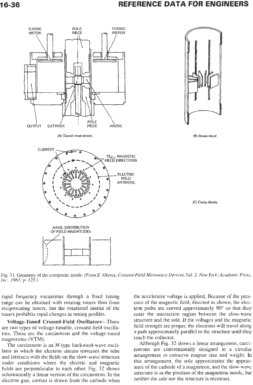
Fig.
31.
Geometry
of
the composite
anode.
(From
E.
Okress, Crossed-Field Microwave Devices,
Vol.
2,
New
York: Academic Press,
Inc.,
1961;~.
125.)
rapid frequency excursions through a fixed tuning
range can be obtained with rotating tuners than from
reciprocating tuners, but the rotational inertia
of
the
tuners prohibits rapid changes in tuning profiles.
Voltage-Tuned Crossed-Field Oscillators-There
are two types
of
voltage-tunable, crossed-field oscilla-
tors. These are the carcinotron and the voltage-tuned
magnetrons (VTM).
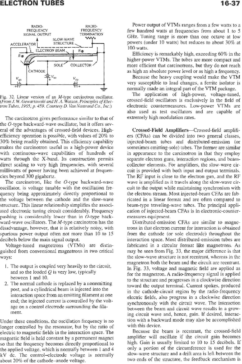
The carcinotron is an M-type backward-wave oscil-
lator in which the electron stream traverses the tube
and interacts with the fields on the slow-wave structure
under conditions where the electric and magnetic
fields are perpendicular to each other. Fig.
32
shows
schematically a linear version of the carcinotron.
In
the
electron gun. current is drawn from the cathode when
the accelerator voltage is applied. Because of the pres-
ence
of
the magnetic field, directed
as
shown, the elec-
tron paths are curved approximately
90"
so
that they
enter the interaction region between the slow-wave
structure and the sole. If the voltages and the magnetic
field strength are proper, the electrons will travel along
a path approximately parallel to the structure until they
reach the collector.
Although Fig.
32
shows a linear arrangement, carci-
notrons are conventionally designed in a circular
arrangement to conserve magnet size and weight.
In
this arrangement, the sole approximates the appear-
ance of the cathode
of
a
magnetron, and the slow-wave
structure is in the position of the magnetron anode, but
neither the sole nor the structure is reentrant.
16-37
RADIO- RADIO-
FREQUENCY FREQUENCY
SIGNAL
OUTPUT
TERMINATION
SLOW WAVE
Fig.
32. Linear
version
of
an
M-type
carcinotron
oscillator.
(From
J.
W.
Gewartowski and
H.
A.
Watson, Principles
of
Elec-
tron Tubes,
1965;
p.
459.
Courtesy
D.
Van Nostrand Co., Inc.)
The carcinotron gives performance similar to that of
the 0-type backward-wave oscillator, but it offers sev-
eral of the advantages of crossed-field devices. High-
efficiency operation is possible, with values of
20%
to
30%
being readily obtained. This efficiency capability
makes the carcinotron useful as a high-power device
with continuous-wave capabilities of hundreds of
watts through the X-band. Its construction permits
direct scaling to very high frequencies, with several
milliwatts
of
power having been achieved at frequen-
cies beyond
300
gigahertz.
The carcinotron, like the 0-type backward-wave
oscillator, is voltage tunable with the oscillation fre-
quency being approximately directly proportional to
the voltage between the cathode and the slow-wave
structure.
This
linear relationship simplifies the associ-
ated electronic tuning circuit considerably. Frequency
pushing is considerably lower than in 0-type back-
ward-wave oscillators. The M-type carcinotron has the
disadvantage, however, that it is relatively noisy, with
spurious power output often not more than 10 to
15
decibels below the main signal output.
Voltage-tuned magnetrons (VTMs) are distin-
guished from conventional magnetrons in two critical
ways:
1.
The output is coupled very heavily to the circuit,
and
so
the loaded
Q
is very low, typically
between
1
and 10.
2.
The normal cathode is replaced by a nonemitting
post, and a cylindrical beam is injected into the
interaction space from an emitting filament at one
end; the injected current is controlled by the volt-
age
on
a
control electrode surrounding the fila-
ment.
Under these conditions, the oscillation frequency is
no
longer controlled by the resonator, but by the ratio of
electric to magnetic fields in the interaction space. The
magnetic field is held constant by a permanent magnet
so
that the frequency becomes directly proportional to
the applied voltage, which is normally between
1
and
4
kV dc. The control-electrode voltage is normally
about
20%
of
the cathode-anode voltage.
Power output of VTMs ranges from a few watts to a
few hundred watts at frequencies from about
1
to
5
GHz. Tuning range is more than one octave at low
powers (under
10
watts) but reduces to about
30%
at
100
watts.
Efficiency is remarkably high, exceeding
60%
in the
higher-power VTMs. The tubes are more compact and
more efficient that carcinotrons, but they do not reach
as high an absolute power level or as high a frequency.
Because the heavy coupling would make the VTM
very susceptible to load changes, a ferrite isolator is
normally made an integral part of the VTM package.
The application of high-power, voltage-tuned,
crossed-field oscillators is exclusively in the field of
electronic countermeasures. Low-power VTMs are
also used as test oscillators and are capable of
extremely high modulation rates.
Crossed-Field Amplifiers-Crossed-field amplifi-
ers (CFAs) can be divided into two general classes,
injected-beam tubes and distributed-emission (or
sometimes emitting-sole) tubes. The former are similar
in appearance to the carcinotron in that they employ
separate electron guns, interaction regions, and beam-
collector elements. For amplifiers, the slow-wave cir-
cuit is provided with both input and output terminals.
The RF input is close to the electron gun, and the
RF
wave is amplified as it travels along
the
slow-wave cir-
cuit to the output while maintaining synchronism with
the electron stream. Most injected-beam CFAs are fab-
ricated in a linear format and are often compared to
beam-type traveling-wave tubes. The principal appli-
cation of injected-beam CFAs is in electronic-counter-
measures equipment.
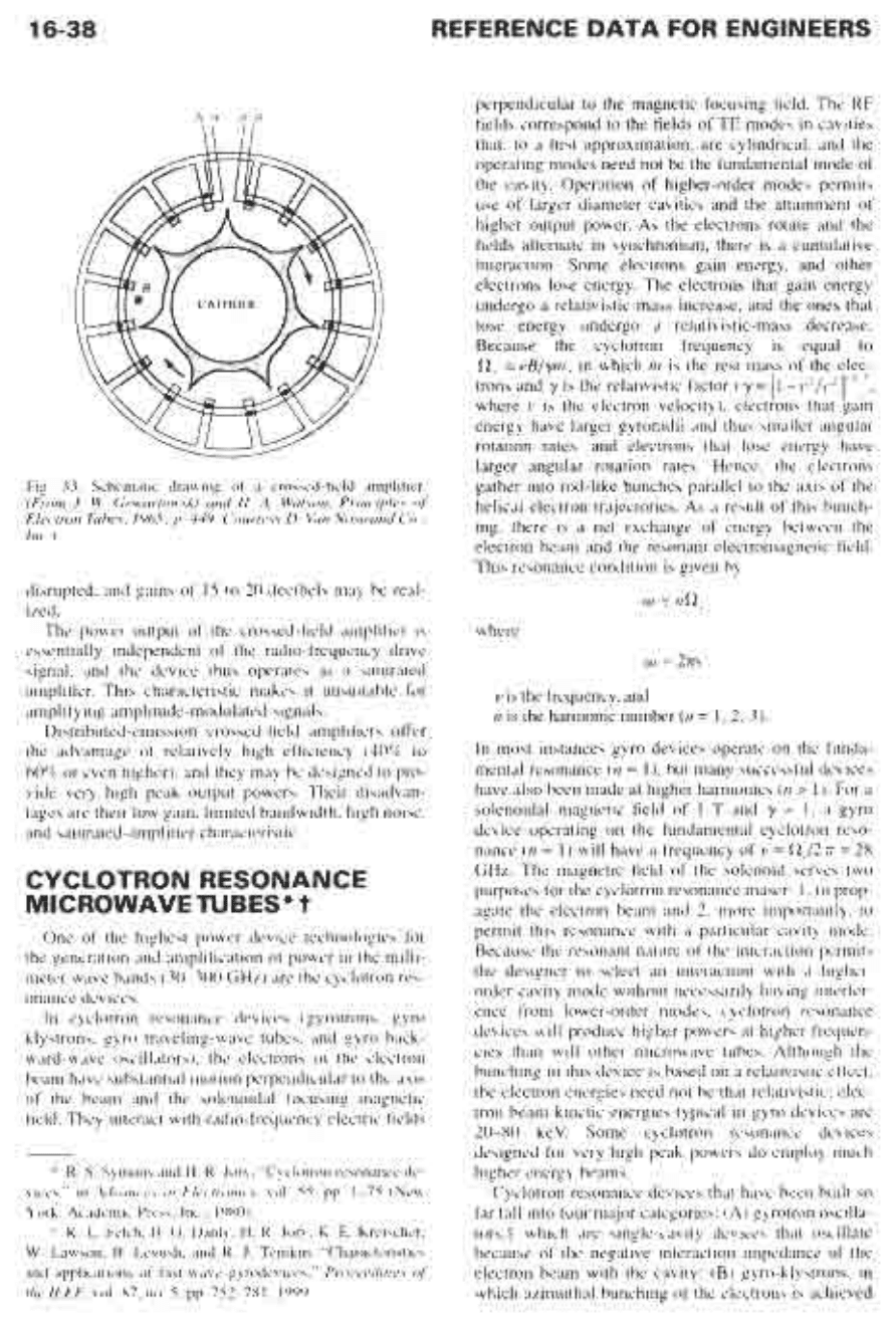
Distributed-emission CFAs are similar to magne-
trons in that electron current for interaction is obtained
from the cathode (or sole electrode) throughout
the
interaction space. Most distributed-emission tubes are
fabricated in a circular format like magnetrons. As
may be seen from Fig.
33,
the major difference is that
the slow-wave structure is not reentrant, whereas in the
magnetron both the beam and the circuit are reentrant.
In
Fig.
33,
voltage and magnetic field are applied as
for the magnetron. A radio-frequency signal is applied
to the structure and progresses in a clockwise direction
toward the output terminal. Current spokes, produced
in
the
cathode-circuit region by the radio-frequency
electric fields, also progress in a clockwise direction
synchronously with the circuit wave. The interaction
between the beam and circuit wave results in a grow-
ing circuit wave and, hence, gain. If desired, interac-
tion with a backward mode may also be accomplished
with this device.
Because the beam
is
reentrant, the crossed-field
amplifier will oscillate if the circuit gain becomes
high. Gain is usually limited
to
10 to
15
decibels.
If
only
a
portion
of
the circumference is used for the
slow-wave structure and a drift area is left between the
two ends of the structure, the feedback mechanism is
16-38
REFERENCE DATA FOR ENGINEERS
A A'
B E'
Fig. 33. Schematic drawing
of
a crossed-field amplifier.
(From
J.
W.
Gewartowski and
H.
A, Watson, Principles
of
Electron Tubes, 1965:
p.
449. Courtesy
D.
Van Nostrand
Co.,
Inc.)
disrupted, and gains of
15
to
20
decibels may be real-
ized.
The power output of the crossed-field amplifier is
essentially independent of the radio-frequency drive
signal, and the device thus operates as a saturated
amplifier. This characteristic makes it unsuitable for
amplifying amplitude-modulated signals.
Distributed-emission crossed-field amplifiers offer
the advantage of relatively high efficiency
(40%
to
60%
or even higher), and they may be designed to pro-
vide very high peak output powers. Their disadvan-
tages are their low gain, limited bandwidth, high noise,
and saturated-amplifier characteristic.
CYCLOTRON RESONANCE
MICROWAVE
TUBES"
t
One of the highest power device technologies for
the generation and amplification of power in the milli-
meter wave bands
(30-300
GHz) are the cyclotron res-
onance devices.
In cyclotron resonance devices (gyrotrons, gyro
klystrons, gyro traveling-wave tubes, and gyro back-
ward-wave oscillators), the electrons in the electron
beam have substantial motion perpendicular to the axis
of the beam and
the
solenoidal focusing magnetic
field. They interact with radio-frequency electric fields
*
R.
S.
Symons
and
H.
R.
Jory,
"Cyclotron resonance de-
vices,"
in
Advances in Electronics,
vol.
55,
pp. 1-75
(New
York: Academic
Press,
Inc., 1980).
t
K.
L.
Felch,
B.
G.
Danly,
H.
R.
Jory,
K.
E.
Kreischer,
W.
Lawson,
B.
Levush, and
R.
J.
Temkin, "Characteristics
and applications of fast-wave gyrodevices,"
Proceedings
of
the IEEE.
vol. 87, no.
5,
pp.
752-781, 1999.
perpendicular to
the
magnetic focusing field. The
RF
fields correspond to the fields
of TE
modes in cavities
that, to a first approximation,
are
cylindrical, and the
operating modes need not
be
the fundamental mode of
the
cavity. Operation of higher-order modes permits
use of larger diameter cavities and
the
attainment of
higher output power.
As
the electrons rotate and
the
fields alternate in synchronism, there is a cumulative
interaction. Some electrons gain energy, and other
electrons lose energy. The electrons that gain energy
undergo a relativistic-mass increase, and
the
ones that
lose
energy undergo a relativistic-mass decrease.
Because
the
cyclotron frequency is equal to
flc
=
eBJym,
in which
m
is the rest mass of the elec-
trons and
y
is the relativistic factor
(
y
[I
-
Y~/C~]-''*,
where
v
is the electron velocity), electrons that gain
energy have larger gyroradii and thus smaller angular
rotation rates, and electrons that lose energy have
larger angular rotation rates. Hence, the electrons
gather into rod-like bunches parallel to the axis of the
helical electron trajectories.
As
a result of this bunch-
ing, there is a net exchange
of
energy between the
electron beam and the resonant electromagnetic field.
This resonance condition is given by
w
Gnfl,
where
w
=
2m3
vis the frequency, and
n
is
the harmonic number
(n
=
1,2,3).
In
most instances gyro devices operate on the funda-
mental resonance
(n
=
l),
but many successful devices
have also been made at higher harmonics
(n
>
1).
For
a
solenoidal magnetic field of
1
T
and
y
=
1,
a gyro
device operating on the fundamental cyclotron reso-
nance
(n
=
1)
will have a frequency of
v
=
flZ,J277
=
28
GHz.
The
magnetic field of the solenoid serves two
purposes for the cyclotron resonance maser:
1.
to prop-
agate the electron beam and
2.
more importantly, to
permit this resonance with a particular cavity mode.
Because the resonant nature of the interaction permits
the designer to select an interaction with a higher-
order cavity mode without necessarily having interfer-
ence from lower-order modes, cyclotron resonance
devices will produce higher powers at higher frequen-
cies than will other microwave tubes. Although the
bunching in this device is based on a relativistic effect,
the electron energies need not be that relativistic; elec-
tron beam kinetic energies typical in gyro devices
are
20-80
keV. Some cyclotron resonance devices
designed for very high peak powers do employ much
higher energy beams.
Cyclotron resonance devices that have been built
so
far fall into four major categories:
(A)
gyrotron oscilla-
tors,S which are single-cavity devices that oscillate
because of the negative interaction impedance of the
electron beam with the cavity;
(B)
gyro-klystrons, in
which azimuthal bunching of the electrons is achieved
ELECTRON
TUBES
16-39
by first passing them through an input cavity wherein
the microwave signal to be amplified is injected, then
through successive beam-excited bunching cavities,
and then through a final output cavity in which the
energy extraction is achieved; (C) gyro-traveling-wave
tubes (gyro-TWTs),
in
which the electrons travel
through a uniform or tapered waveguide supporting a
transverse electric mode; and
(D)
gyro backward-wave
oscillators, which
are
similar in structure
to
gyro-
TWTs but in which the group velocity of the wave in
the uniform waveguide is opposed to electron flow and
power comes
out
of the circuit at the end where the
electron beam enters.
Gyrotron oscillators are by far the best developed of
these four categories. The principle applications are
scientific and include applications to the cyclotron res-
onance heating of fusion plasmas and material pro-
cessing. Representative of present state of the
art
for
gyrotron oscillators is a 110-GHz gyrotron capable of
operation at
1
MW for 0.6-s pulses, 400 kW for 6.5s
pulses, and
100
kW CW.* To achieve these unprece-
dented powers without thermal damage to the interac-
tion circuit, this device was operated in a very high
order cavity mode, the TE,,,,., mode. Consequently,
gyrotrons often now have internal mode converters
that convert the TE mode used in the interaction to a
more usable output mode, such as a TEW0 Gaussian
beam. Gyrotrons have been developed or are under
development at frequencies ranging from
8
to 170
GHz. Gyrotrons at even higher frequencies (up to
800
GHz) have been developed for scientific applications.
Though they have received less development than
gyrotroii oscillators, gyro-amplifiers such as the gyro-
klystron have been developed in several frequency
bands with radar and accelerator applications as the
primary motivation. As an example, a 90-kW peak
power, 10-kW average power gyro-klystron amplifier
has been developed at 94 GHz for radar applications.
The device has an instantaneous bandwidth of 600
MHz, an efficiency of 33%, and operates with a 65-kV,
6-A electron beam.?
A
second device delivered the
same average power at
700
MHz bandwidth, and it
offers a 1-GHz bandwidth at 4-kW average power.
This represents more than an order of magnitude
higher average power than is available from any other
$
Gyrotron Oscillators: Their Principles and Practice,
ed.
C.
J.
Edgcombe (London: Taylor
&
Francis Ltd, 1993).
*
K.
L.
Felch,
B.
G.
Danly,
H.
R.
Joy,
K.
E.
Kreischer,
W.
Lawson,
B.
Levush, and
R.
J.
Temkin, “Characteristics
and applications of fast-wave gyrodevices,”
Proceedings
of
the
IEEE,
vol. 87, no. 5, pp. 752-781, 1999.
t
B.
G. Danly,
M.
Blank,
J.
P.
Calame,
B.
Levush,
K.
T.
Nguyen, D.
E.
Pershing,
R.
K.
Parker,
K.
L. Felch,
B.
G.
James, P. Borchard, P. Cahalan, T.
S.
Chu, H.
R.
Jory,
T.
A.
Hargreaves,
R.
B.
True,
W.
G. Lawson,
and
T.
M.
Antonsen,
Jr., “Development and
testing
of
a high-average power 94-
GHz gyroklystron”,
IEEE
Trans. Plasmn Science,
vol.
28, no.
3, pp. 713-726,2000.
amplifier technology at this frequency. Gyro-klystron
amplifiers behave as coherent amplifiers of the input
signal, and they have been demonstrated to have low
phase noise comparable to that obtained from
klystrons, with -147 dBc/Hz
SSB
phase noise at
10
MHz offset from the carrier in one experimental
device when operated with a carrier at 200-kW output
power at 35 GHz.4
Experimental gyro-klystrons at high peak power
levels in the microwave bands have also been devel-
oped for powering RF linear accelerators. Experimen-
tal devices designed for this application have achieved
27-MW peak power at 9.87 GHz at the fundamental
(n
=
1)
cyclotron resonance device, and 32-MW peak
power has been obtained at 19.76 GHz in a second har-
monic
(n
=
2) device.§
Future efforts in the development
of
the cyclotron
resonance or gyrotron-class of devices are directed
toward higher power oscillators for fusion applica-
tions, more compact and efficient oscillators for indus-
trial processing applications, and gyro-amplifiers such
as the gyro-klystron and gyro-TWT for high-power
millimeter-wave radar and accelerator applications.
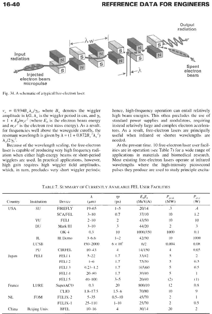
FREE-ELECTRON LASERS
Free-electron lasers (which are also called ubitrons
when applied to microwaves millimeter waves) consist
of an electron beam propagating through a periodic
transverse magnetic field (called a
wiggler
or
undula-
tor)
that induces motion perpendicular to the axis of
symmetry.” A schematic illustration of a free-electron
laser is shown in Fig. 34.
The wiggler and the radiation combine
to
produce a
beat wave, which is essentially an interference pattern,
that exerts a slowly varying ponderomotive force
on
the electrons. Because the electrons experience a near-
constant field the interaction can be extremely strong.
Stimulated emission occurs when electrons form
coherent bunches over a wavelength. Bunching occurs
because the ponderomotive wave has the same fre-
quency
(w)
as the radiation, but the wavenumber is the
sum of the wavenumbers of the electromagnetic
(k)
and wiggler
(k,)
fields. Hence, the beat wave travels
more slowly than the light wave and can be in synchro-
nism with the electrons when the phase velocity of the
ponderomotive wave equals the electron beam velocity
(vb),
i.e.,
w/(k
+
kw,)
=
vb
The amplitude of the trans-
verse velocity
(v,J
is proportional to the product of the
wiggler
amplitude
and period and inversely
propor-
tional to the relativistic dilation factor. Specifically,
$
J.
P.
Calame,
B.
G. Danly,
M.
Gwen, and
B.
Levush,
“Studies of electronic noise
in
gyroklystrons,”
Phys. Plasmas,
vol. 7, no. 5, pp. 2180-2185,2000.
5
V. L. Granatstein and
W.
Lawson, “Gyro-amplifiers as
candidate
RF
drivers for TeV linear colliders,”
IEEE
Trans.
Plasma Science,
vol.
24,
pp.
648-665, 1996.
”
Reference
44.
1640
output
radiation
electron
beam
micropulse
Fig.
34.
A schematic
of
a
typical free-electron laser.
v,.
=
0.934Bu,h,/y,,,
where
B,.
denotes
the
wiggler
amplitude
in
kG,
A,.
is the wiggler period in cm, and
7/,,
=
1
+
E@,c2
(where
E,,
is the electron
beam
energy
and
m,c-
is
the
electron rest mass energy). As a result,
for frequencies well above
the
waveguide cutoffs, the
resonant wavelength is given by
A
=
(1
+
0.872BM2A,.")
Because of
the
wavelength scaling, the free-electron
laser is capable of producing very high frequency radi-
ation when either high-energy
beams
or
short-period
wigglers
are
used. In practical applications, however,
high gain requires high wiggler field amplitudes,
which, in turn, precludes very short wiggler periods;
Au/2Y,2.
hence, high-frequency operation can entail relatively
high
beam
energies. This often precludes the use of
standard power supplies and modulators, requiring
instead relatively large and complex electron accelera-
tors. As a result, free-electron lasers
are
principally
useful when infrared
or
shorter wavelengths are
needed.
At
the
present time,
10
freeelectron laser user facil-
ities
are
in operation (see Table
7)
for a wide range of
applications
in
materials and biomedical research.
Most existing free-electron lasers operate at infrared
wavelengths where the high-intensity picosecond
pulses they produce
are
used to study principle excita-
TABLE
7.
SUMMARY
OF
CURRENTLY AVAILABLE
EL
USER
FACILITIES
A
7p
Edlh
Pped
pol.*
Country Institution Device
(wm)
(PSI (MeVlA)
(Mw)
(w)
USA
su
W
DU
JL
UCSB
PU
Japan FELI
France
LURE
NL
FOM
China Beijing Univ.
FIREFLY
SCA/FEL
FELI
Mark
TTI
OK4
IR
Demo
CIRFEL
FELI
1
FELT
2
FELI
3
FELI
4
FELI
5
SuperACO
CLIO
FELIX-2
FELIX-]
BEL
19-65
3-10
2-10
3-10
0.3
3-6.6
150-2000
1043
5-22
1-6
0.23-1.2
20-80
40-1
00
0.3
1.8-1
7.5
5-35
25-110
10-16
1
-5
0.7
2
3
10
1
-2
6x
IO6
4
1.7
1.7
1.7
1.7
3-5
20
1.5-6
0.5-10
1-10
4
20114
37/10
43/50
4/20
1
000/350
42/50
6/2
141150
33/42
75/50
165160
30140
20140
800110
70/80
45/70
25/70
30114
.3
10
10
2
1000
10
0.004
4
5
5
5
5
(2)
12
10
2
2
20
.4
1.2
10
3
0.1
1000
0.08
0.05
2
0.5
0.5
1
(1)
0.8
9
1
0.5
2
ELECTRON TUBES
1641
tions
in
condensed matter systems where it is possible
to access the principal excitations such as plasmons,
phonons, magnons, and inter-sub-band transitions.
Direct linear probing of defect modes and buried inter-
faces with bond specificity is possible. Free-electron
lasers have been used for pump probe observation of
coherent transient grating effects of narrow-gap semi-
conductors and third-order nonlinearity coefficients
and electron relaxation times in GaAs/AlGaAs quan-
tum wells. Studies in kinetics include vibrational
energy transfers in molecules and resonant excitations
of molecular vibrations. Applications to neurosurgery
take advantage of particular absorption bands to pro-
duce
an
exceptionally fine cut in bone and tissue. At
shorter wavelengths, freeelectron lasers have been
used
to make measurements of time-resolved fluores-
cence decays of biological molecules, to study time-
resolved photoemission, and photoionization.
There are
two
principal areas of future development
for free-electron laser
(FEL)
technology: high average
powers and ultra-short wavelengths. The high average
power goal is several tens of kilowatts at infrared or
shorter wavelengths, and the most likely configuration
is an oscillator driven by
a
radio-frequency linear
accelerator
(rf
linac). Rates of progress in the develop-
ment of vacuum generators of coherent radiation can
be
gauged by using the power density (the product of
the average power and the square of the frequency) as
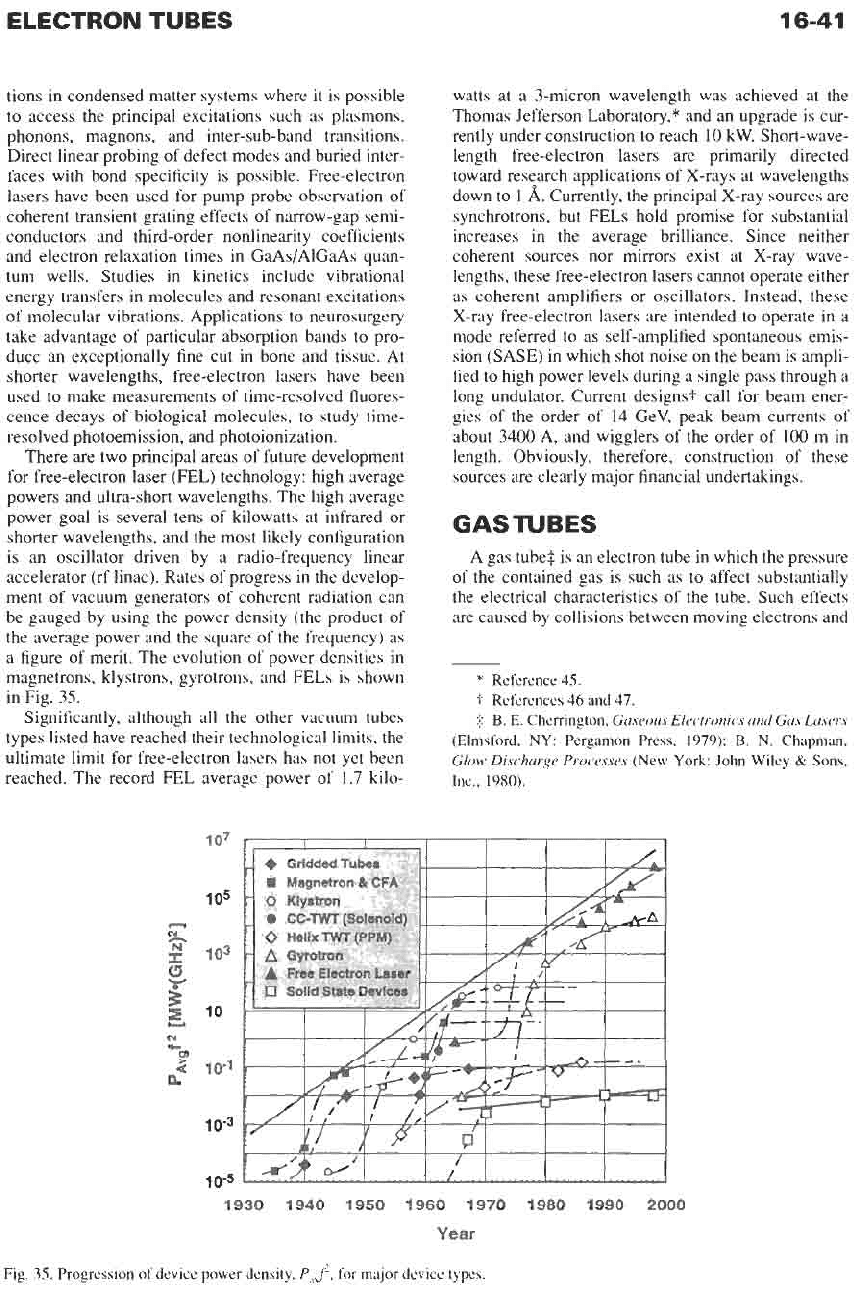
a figure of merit. The evolution of power densities in
magnetrons, klystrons, gyrotrons, and
FELs
is shown
in Fig. 35.
Significantly, although all the other vacuum tubes
types listed have reached their technological limits, the
ultimate limit for free-electron lasers has not yet been
reached. The record
FEL
average power of 1.7 kilo-
watts at a 3-micron wavelength was achieved at the
Thomas Jefferson Laboratory,* and an upgrade is cur-
rently under construction to reach
10
kW.
Short-wave-
length free-electron lasers are primarily directed
toward research applications of X-rays at wavelengths
down to
1
A.
Currently, the principal X-ray sources are
synchrotrons, but
FELs
hold promise for substantial
increases in the average brilliance. Since neither
coherent sources nor mirrors exist at X-ray wave-
lengths, these free-electron lasers cannot operate either
as coherent amplifiers or oscillators. Instead, these
X-ray free-electron lasers are intended to operate in a
mode referred to as self-amplified spontaneous emis-
sion (SASE) in which shot noise
on
the beam is ampli-
fied to high power levels during a single pass through a
long undulator. Current designs? call for beam ener-
gies of the order of 14 GeV, peak beam currents of
about 3400 A, and wigglers of the order of
100
m in
length. Obviously, therefore, construction of these
sources are clearly major financial undertakings.
GASTUBES
A gas
tubes
is an electron tube in which the pressure
of the contained gas is such as to affect substantially
the electrical characteristics of the tube. Such effects
are
caused by collisions between moving electrons and
*
Reference 45.
t
References
46
and 47.
$
B. E. Chemngton,
Gaseous Electronics and Gas Lasers
(Elmsford,
NY:
Pergamon Press, 1979); B.
N.
Chapman,
Glow Discharge Processes
(New
York:
John Wiley
&
Sons,
Inc.,
1980).
0
Klystron
0
CC-TWT
(Solenoid)
0
Helix
TWT
(PPM)
A
GyrohPn
._
-
1
07
105
103
A
Free
Electron
user
10
1
0-1
109
10-5
1930 1940 1950 1960 1970 1980 1990
2000
Year
Fig.
35.
Progression of device
power
density,
Pa$,
for
major device
types.
gas atoms. These collisions, if of sufficient energy,
may dislodge an electron from the atom, thereby leav-
ing the atom as a positive ion. The electron space
charge is effectively neutralized by these positive ions,
and comparatively high free-electron densities are eas-
ily created.
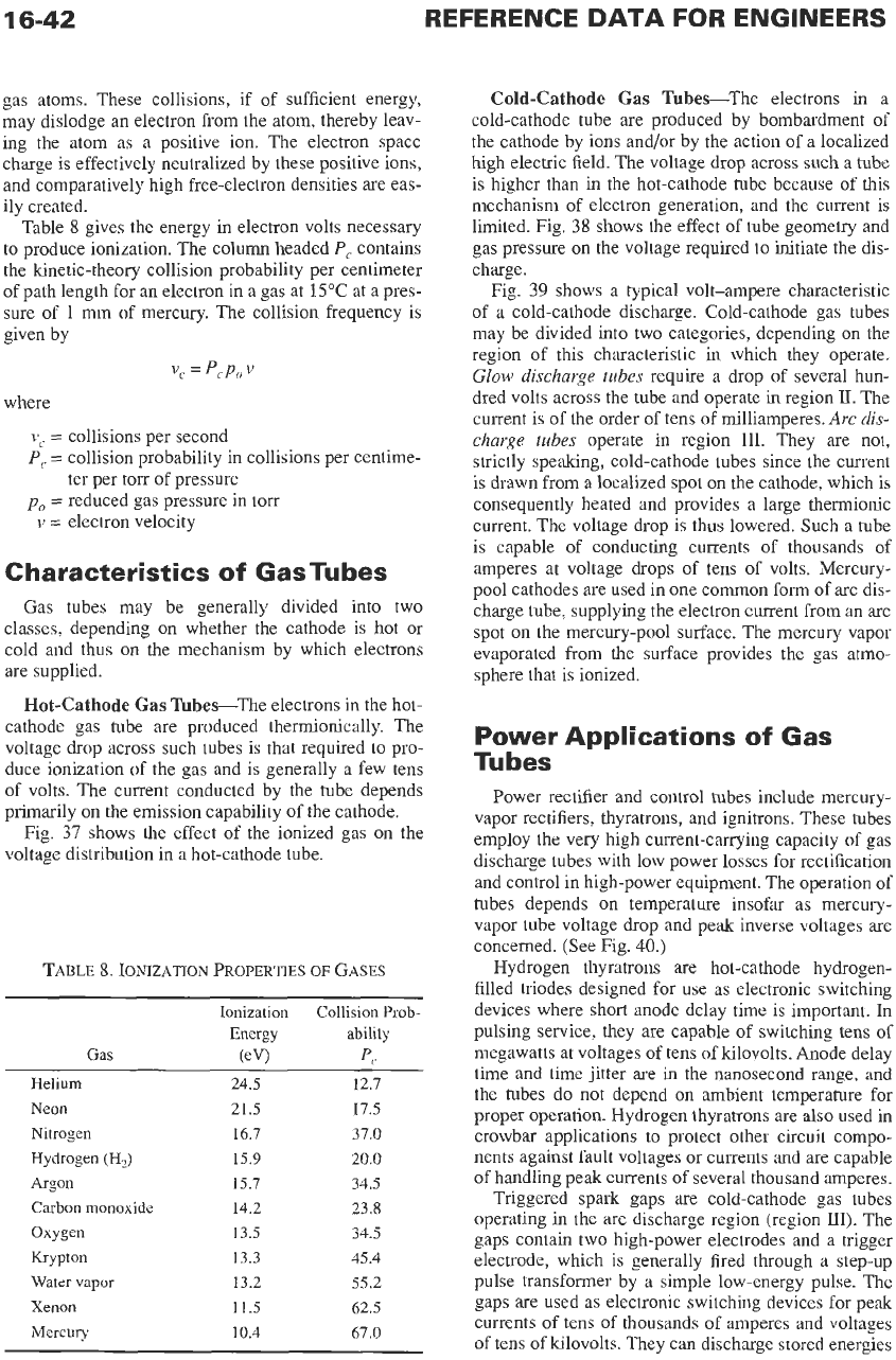
Table
8
gives the energy
in
electron volts necessary
to produce ionization. The column headed
P,
contains
the kinetic-theory collision probability per centimeter
of
path length for an electron in a gas at
15°C
at a pres-
sure
of
1
mm
of
mercury. The collision frequency is
given by
v,
=
p,
Po
v
where
L’,
=
collisions per second
P,
=
collision probability in collisions per centime-
ter per torr of pressure
po
=
reduced gas pressure in torr
v
=
electron velocity
Characteristics
of
GasTubes
Gas tubes may be generally divided into two
classes, depending on whether the cathode is hot or
cold and thus on the mechanism by which electrons
are supplied.
Hot-Cathode
Gas
TubeeThe electrons in the hot-
cathode gas tube are produced thennionically. The
voltage drop across such tubes is that required to pro-
duce ionization of the gas and is generally a few tens
of volts. The current conducted by the tube depends
primarily on the emission capability of the cathode.
Fig.
37
shows the effect of the ionized gas on the
voltage distribution in a hot-cathode tube.
TABLE
8.
IONIZATION
PROPERTIES
OF
GASES
Ionization Collision Prob-
Energy ability
Gas
(eV)
p,
Helium
Neon
Nitrogen
Hydrogen
(H2)
Argon
Carbon monoxide
Oxygen
Krypton
Water vapor
Xenon
Mercury
24.5
21.5
16.7
15.9
15.7
14.2
13.5
13.3
13.2
11.5
10.4
12.7
17.5
37.0
20.0
34.5
23.8
34.5
45.4
55.2
62.5
67.0
Cold-Cathode
Gas
Tubes-The electrons in a
cold-cathode tube are produced by bombardment
of
the cathode by ions and/or by the action of a localized
high electric field. The voltage drop across such a tube
is higher than in the hot-cathode tube because of this
mechanism of electron generation, and the current is
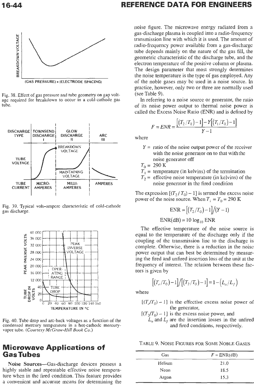
limited. Fig.
38
shows the effect
of
tube geometry and
gas pressure
on
the voltage required
to
initiate the dis-
charge.
Fig.
39
shows a typical volt-ampere characteristic
of
a cold-cathode discharge. Cold-cathode gas tubes
may be divided into two categories, depending on the
region of this characteristic
in
which they operate.
Glow
discharge tubes
require a drop of several hun-
dred volts across the tube and operate
in
region
II.
The
current is of the order
of
tens of milliamperes.
Arc
dis-
charge tubes
operate
in
region
111.
They are not,
strictly speaking, cold-cathode tubes since the current
is
drawn from
a
localized spot on the cathode, which
is
consequently heated and provides a large thermionic
current. The voltage drop is thus lowered. Such a tube
is capable of conducting currents of thousands
of
amperes at voltage drops of tens of volts. Mercury-
pool cathodes are used in one common form of arc dis-
charge tube, supplying the electron current from an arc
spot on the mercury-pool surface. The mercury vapor
evaporated from the surface provides the gas atmo-
sphere that is ionized.
Power Applications
of
Gas
Tubes
Power rectifier and control tubes include mercury-
vapor rectifiers, thyratrons, and ignitrons. These tubes
employ the very high current-caving capacity
of
gas
discharge tubes with low power losses for rectification
and control in high-power equipment. The operation
of
tubes depends on temperature insofar
as
mercury-
vapor tube voltage drop and peak inverse voltages are
concerned. (See Fig.
40.)
Hydrogen thyratrons are hot-cathode hydrogen-
filled triodes designed for use as electronic switching
devices where short anode delay time is important. In
pulsing service, they are capable
of
switching tens
of
megawatts at voltages
of
tens
of
kilovolts. Anode delay
time
and time jitter are
in
the nanosecond range, and
the tubes do not depend on ambient temperature for
proper operation. Hydrogen thyratrons are
also
used in
crowbar applications to protect other circuit compo-
nents against fault voltages or currents and are capable
of handling peak currents of several thousand amperes.
Triggered spark gaps are cold-cathode gas tubes
operating in the arc discharge region (region
HI).
The
gaps contain two high-power electrodes and a trigger
electrode, which is generally fired through
a
step-up
pulse transformer by
a
simple low-energy pulse. The
gaps are used as electronic switching devices for peak
currents of tens of thousands
of
amperes and voltages
of tens of kilovolts. They can discharge stored energies
ELECTRON
TUBES
16-43
1000
100
i
2
10
1
1
VARlAN
X-3030
10
100
FREQUENCY
(GHz)
1000
8
Labomtoy
result
MK
us
pulsed
0
Published
Russian
wotron
data
0
Russian
0.5
second
pulsed
gyrotrons
Klystrons
7wTs
and
extended-interaction
klystrons
8
Varian
CW
gyrotron
*
Russian
100
pulsed
gyrotron
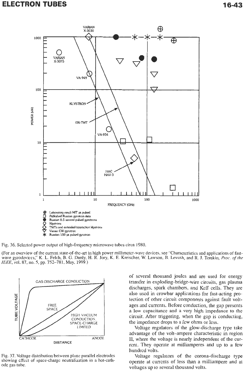
Fig. 36. Selected power output of high-frequency microwave tubes circa 1980.
(For
an
overview of the current state-of-the-art in high power millimeter-wave devices,
see
“Characteristics and applications of fast-
wave gyrodevices,”
K.
L. Felch,
B.
G.
Danly, H.
R.
Jory,
K.
E.
Kreischer,
W.
Lawson,
B.
Levush,
and
R.
J.
Temkin,
Proc.
of
the
IEEE,
vol. 87,110.5,~~. 752-781,May, 1999.)
CONDUCTION.
SPACE-CHARGE
LIMITED
:ATHODE
ANODE
DISTANCE
of several thousand joules and are used for energy
transfer
in
exploding-bridge-wire circuits, gas plasma
discharges, spark chambers, and Keff cells. They are
also used in crowbar applications for fast-acting pro-
tection of other circuit components against fault volt-
ages and currents. Before conduction, the gap presents
a
low
capacitance and a very high impedance
to
the
circuit. After triggering, when the gap is conducting,
the impedance drops to a few
ohms
or less.
Voltage regulators
of
the glow-discharge type take
advantage of the volt-ampere characteristic in region
11,
where the voltage is nearly independent of the cur-
rent. They operate at milliamperes and
up
to a few
hundred volts.
Fig. 37. Voltage distribution between plane parallel electrodes
showing effect
of
space-charge neutralization in
a
hot-cath-
ode
gas
tube.
Voltage regulators of the corona-discharge type
and at
operate
at
culTentS
of
less
than a
voltages up to several thousand volts.
16-44
REFERENCE
DATA
FOR ENGINEERS
Fig.
38.
Effect
of
gas pressure and tube geometry on gap volt-
age required
for
breakdown
to
occur in
a
cold-cathode gas
tube.
I
ABREAKDOWN
VOLTAGE
A
AMPERES
VOLTAGE
MILLI-
I
I
Fig.
39.
Typical volt-ampere characteristic
of
cold-cathode
gas
discharge.
40
000
v)
5
36
000
0
>
32
000
w
2
28000
'
24
000
z
3
20000
16
000
12
000
40
0
20 40
60
80
100 120 140 160
TEMPERATURE
IN
OC
Fig.
40.
Tube
drop
and
arc-back
voltages
as
a
function
of
the
condensed mercury temperature
in
a
hot-cathode mercury-
vapor
tube.
(Courtesy
McGruw-Hill
Book
Co.)
Microwave Applications
of
GasTubes
Noise
Sources-Gas-discharge devices possess a
highly stable and repeatable effective noise tempera-
ture when in the fired condition. This feature provides
a convenient and accurate means for determining the
noise figure. The microwave energy radiated
from
a
gas-discharge plasma is coupled into a radio-frequency
transmission line with which it is used. The amount of
radio-frequency power available from a gas-discharge
tube depends mainly on the nature of the gas fill, the
geometric characteristic of the discharge tube, and the
electron temperature of the positive column or plasma.
The design parameter that most strongly determines
the noise temperature
is
the type
of
gas employed. Any
of the noble gases may be used in a noise source.
In
practice, however, only two or three are normally used
(see Table
9).
In referring to a noise source or generator, the ratio
of its noise power output to thermal noise power is
called the Excess Noise Ratio
(EM)
and is defined by
where
Y
=
ratio of the noise output power
of
the receiver
with the noise generator on to that with the
noise generator
off
To
=
290
K
TI
=
temperature
(in
kelvins) of the termination
T2
=
effective noise temperature (in kelvins) of the
noise generator in the fired condition
The expression
[(T2/ To)
-
11
is termed the excess noise
power of the noise source. When
T,
=
To
=
290
K
=
[
(T2
/To)
-
1]/P
-
1)
ENR(dB)
=
10
log,,
ENR
The effective temperature
of
the noise source is
equal
to
the temperature of the discharge only if the
coupling
of
the transmission line
to
the discharge is
complete. Otherwise, there is a reduction in the noise
power output that can best be determined by measur-
ing the fired and unfired insertion loss of the unit at the
frequency of interest. The relation between these fac-
tors is given by
[(T,
/To
1
-
1]/[(T2
/To
1
-
11
=
1
-
(L,/Lf)
where
[(T,/TO)
-
11
is the effective excess noise power
of
[(T2/To)
-
11
is the excess noise power, and
the generator,
L,
and
Lf
are the insertion losses in the unfired
and ked conditions, respectively.
TABLE
9.
NOISE
FIGURES
FOR
SOME
NOBLE
GASES
Gas
F
=
ENR(dB)
Helium
21.0
Neon
18.5
Argon
15.3
ELECTRON TUBES
16-45
This correction should be subtracted from the apparent
measured noise figure. The noise figure is always mea-
sured with reference to a standard temperature of
290
K
(To).
If the ambient temperature
(TI)
of the noise-
generator termination differs from the standard tem-
perature, the noise figure calculated must be corrected.
To find the correction factor, substitute the ambient
temperature of the noise-generator termination for
TI,
in
the following equation, and add the temperature fac-
tor
(F,)
to the noise figure calculated.
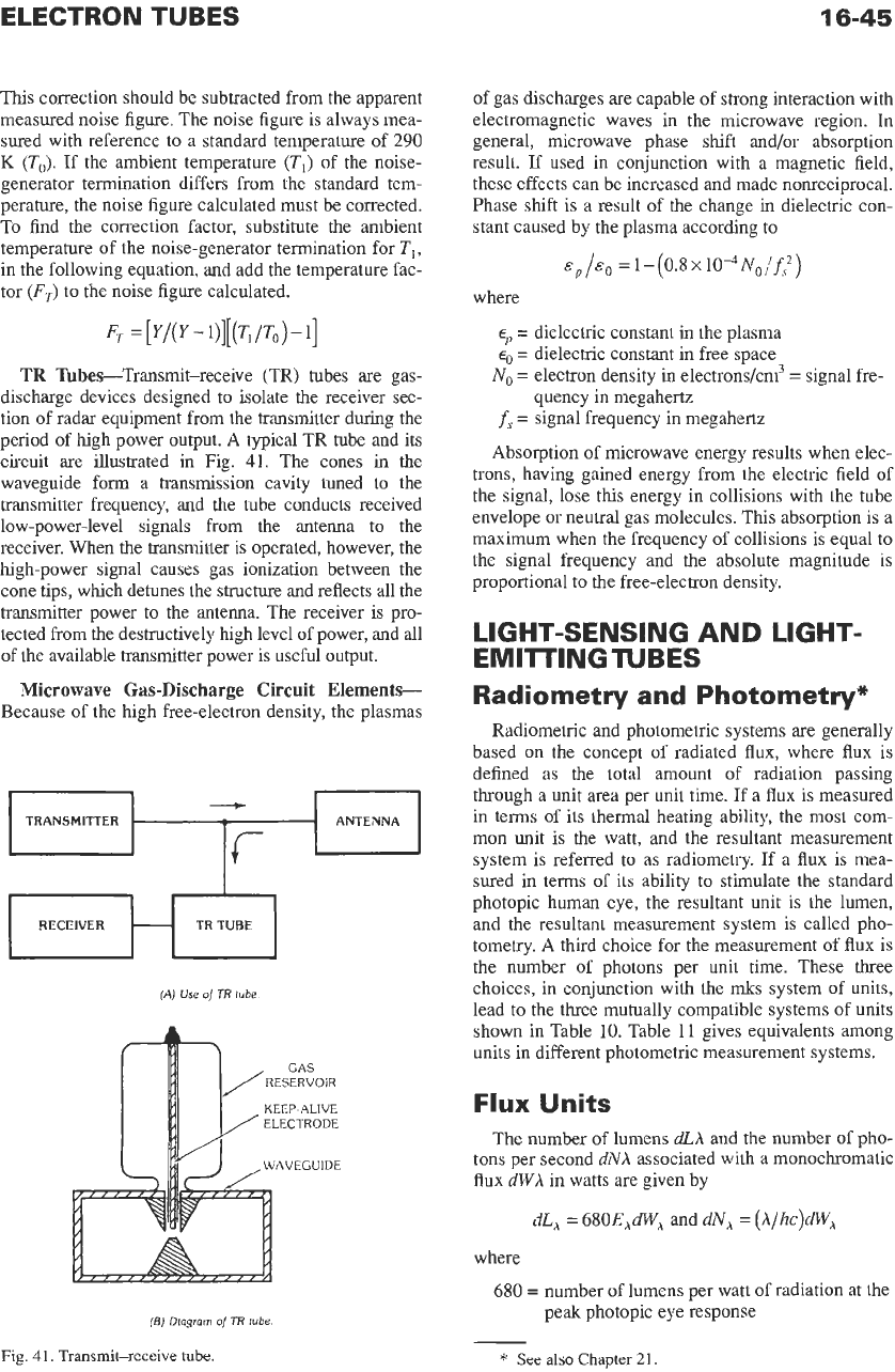
TR
Tubes-Transmit-receive (TR) tubes
are
gas-
discharge devices designed to isolate
the
receiver sec-
tion of radar equipment from the transmitter during the
period of high power output. A typical TR tube and its
circuit are illustrated
in
Fig.
41.
The cones
in
the
waveguide form a transmission cavity tuned to the
transmitter frequency, and the tube conducts received
low-power-level signals from the antenna to the
receiver. When
the
transmitter is operated, however, the
high-power signal causes gas ionization between the
cone tips, which detunes the structure and reflects all the
transmitter power to the antenna.
The
receiver
is
pro-
tected from
the
destructively high level of power, and all
of the available transmitter power
is
useful output.
Microwave
Gas-Discharge
Circuit
Elements
Because of the high free-electron density, the plasmas
TRANSMITTER ANTENNA
RECEIVER TR
TUBE
(A)
Use
of
TR
tube
KEEP-ALIVE
(B)
Dlagrorn
of
TR
tube
Fig.
41.
Transmit-receive
tube.
of gas discharges are capable of strong interaction with
electromagnetic waves in the microwave region.
In
general, microwave phase shift and/or absorption
result.
If
used in conjunction with a magnetic field,
these effects can be increased and made nonreciprocal.
Phase shift is a result of the change in dielectric con-
stant caused by the plasma according to
=
1-
(0.8
x1O4N0/f~)
where
eP
=
dielectric constant
in
the plasma
eo
=
dielectric constant in free space
No
=
electron density in electrons/cm3
=
signal fre-
quency in megahertz
f,
=
signal frequency in megahertz
Absorption
of
microwave energy results when elec-
trons, having gained energy from the electric field of
the signal, lose this energy in collisions with the tube
envelope or neutral gas molecules. This absorption is a
maximum when the frequency of collisions
is
equal to
the signal frequency and the absolute magnitude is
proportional to the free-electron density.
LIGHT-SENSING AND LIGHT-
EMITTINGTUBES
Radiometry and Photometry*
Radiometric and photometric systems
are
generally
based
on
the concept
of
radiated
flux,
where flux is
defined as the total amount
of
radiation passing
through a unit area per unit time. If a flux is measured
in terms of its thermal heating ability, the most com-
mon unit
is
the watt, and the resultant measurement
system is referred to as radiometry. If a flux is mea-
sured in terms of its ability to stimulate the standard
photopic human eye, the resultant unit is the lumen,
and the resultant measurement system is called pho-
tometry. A third choice for the measurement of flux is
the number of photons per unit time. These three
choices,
in
conjunction with the
mks
system of units,
lead to the three mutually compatible systems of units
shown in Table
10.
Table
11
gives equivalents among
units in different photometric measurement systems.
Flux
Units
The number
of
lumens
dLA
and the number
of
pho-
tons per second
dNA
associated with a monochromatic
flux
dWA
in watts are given by
dL,
=
680E,dW,
and
dN,
=
(A/hc)dW,
where
680
=
number
of
lumens per watt
of
radiation at the
peak photopic eye response
*
See
also
Chapter
21.