Middleton W.M. (ed.) Reference Data for Engineers: Radio, Electronics, Computer and Communications
Подождите немного. Документ загружается.

17-6
REFERENCE
DATA
FOR ENGINEERS
ic
=
0.3 ampere
i,'
=
1.7 amperes
i,"
=
-0.1 ampere
i:
=
0
ampere
E,
=
-1000
volts
e,'
=
740 volts
"Ep
=
10
000
volts
From the equations, complete carrier data as follows
are calculated.
MIP
=
[I3
+
1.73
X
10
+
0.3]/6
=
5.1
amperes
Po
=
(10
000
X
5.1)12
=
25
500 watts
I,
=
[13
+
2
X
10
+
2
X
0.3]/12
=
2.8
amperes
Pi
=
12
000
x
2.8
=
33 600 watts
r]
=
(25
500133 600)
X
100
=
76 percent
R,
=
(10 000/5.1)
=
1960 ohms
I,
=
[1.7
+
2(-0.1)]112
=
0.125
ampere
MI,
=
[1.7
+
1.7(-0.1)]/6
=
0.255
ampere
Pg
=
(1740
X
0.255)/2
=
220
watts
Operating data at 100-percent positive modulation
crests are now calculated based
on
the fact that here
E,
=
24
000
Volts
R,
=
1960 ohms
and for undistorted operation
Po
=
4
X
25
500
=
102
000
watts
MEP
=
20
000
volts
The crest operating line A'B
'
is now located by trial
so
as to satisfy the above conditions, by the use of the
same equations and method as for the carrier condition.
It is seen that to obtain full-crest power output, in
addition to doubling the alternating plate voltage, the
peak plate current must be increased. This is accom-
plished by reducing the crest bias voltage with a
resultant increase
of
current conduction period but
lower plate efficiency.
The effect of grid secondary emission to lower the
crest grid current is taken advantage of to obtain the
reduced grid-resistance voltage drop required. By use of
combination fixed and grid-resistance bias, proper
variation of the total bias is obtained. The value
of grid
resistance required is given by
R,
=
-(E,
-
CreStEC)l(IC
-
c""l,)
and the value of fixed bias by
Calculations at carrier and positive crest together with
the condition of zero output at negative crest give
sufficiently complete data for most purposes. If accurate
calculation of audio-frequency harmonic distortion is
necessary, the above method may be applied to the
additional points required.
Class-B
RF
Amplifiers
A rapid approximate method is to determine by
inspection from the tube
ib-e,
characteristics the instan-
taneous current,
ib'.
and voltage,
e,',
corresponding to
the peak alternating voltage swing from operating
voltage
E,.
Ac plate current:
MIP
=
ib1/2
Dc plate current:
Ac plate voltage:
Power output:
Po
=
[(Eb
-
eb')ib']/4
Power input:
Plate efficiency:
Thus
r]
=
0.6
for the usual crest value of
MEP
=
0/8
E,.
The same method of analysis used for the class-C
amplifier may also be used in this case. The carrier and
crest-condition calculations, however, are now made
from the same
E,,
the carrier condition corresponding
to an alternating-voltage amplitude
of
MEp/2
such as to
give the desired carrier power output.
For greater accuracy than the simple check of carrier
and crest conditions, the radio-frequency plate currents
may be calculated for seven corresponding selected
MI~I,
M
Ip,
II
M
Ip
111
,
M
lp
0
,
-MI
iff
,
and
POWER GRID-TUBE CIRCUITS
17-7
points of the audio-frequency modulation envelope
+ME,,
+0.707ME
+O.S'E,,
0,
-0.5ME,,
denote values in the negative half of the modulation
cycle. If the designations
=
Mip'
-
(-Mip!)
-0.707'E,,
and
-
Q
E,,
where the negative signs
D'
=
+
-
2MI
P
are used, the fundamental and harmonic components of
the output audio-frequency current are obtained as
MIpi
=
(S'/4)
+
[S"/2(2)i'2]
(fundamental)
MIp2
=
(5Dt/24)
+
(D"/4)
-
(Dfff/3)
MIp3
=
(S'/6)
-
(Sff'/3)
Mlp4
=
(D'i8)
-
(D"/4)
MIp5
=
(S'/12)
-
[S"/2(2)"*1
+
(S"'/3)
MIp6
=
(D'/24)
-
(D"/4)
+
(Dfff/3)
This detailed method of calculation of audio-frequency
harmonic distortion may,
of
course, also be applied to
calculation of the class-C modulated amplifier, as well
as to the class-A modulated amplifier.
Class-A and -AB
AF Amplifiers
Approximate equations assuming linear tube
Maximum undistorted power output
characteristics:
MPo
=
("EpMIP)/2
when plate load resistance
and negative grid bias
E,
=
('Ep/~L)[(Ri
+
rPY(Ri
+
rpY(Ri
+
2rp)l
giving maximum plate efficiency
7
=
M.??pMIp/8EbIb
Maximum maximum undistorted power output
MMPo
=
MEi/16rp
when
Rl
=
2rp
E,
=
i('Ep/p)
An exact analysis may be obtained by use of
a
dynamic load line laid out on the transfer characteristics
of
the tube. Such
a
line is CKF of Fig.
2,
which is
constructed about operating point K for a given load
resistance
rl
from
ibs
=
[(ebR
-
ebS)/~~]
+
ibR
where
R,
S,
etc., are successive conveniently spaced
construction points.
Using the seven-point method of harmonic analysis,
plot instantaneous plate currents
ib', i{, i:, ib,
-iF,
-it,
and
-ib',
corresponding to
fME,,
+0.707ME,,
+O.SME,,
0,
-OSME,, -0.707ME,,
and
-ME,,
where
0
corresponds to operating point
K.
In addition
to the equations given under class-B radio-frequency
amplifiers
1,
average
=
I,
+
(D'/8)
+
(0"/4)
from which complete data may be calculated
Class-AB and
-B
AF Amplifiers
Approximate equations assuming linear tube
characteristics give (referring to Fig.
1,
line CD) for
a
class-B audio-frequency amplifier
An exact solution may be derived by use of dynamic
load line JKL
on
the
ib-ec
characteristic of Fig.
2.
This
line is calculated about the operating point
K
for the
given
Rl
(in the same way as for the class-A case).
However, since two tubes operate in phase opposition in
this case, an identical dynamic load line MNO repre-
sents the other half cycle, laid out about the operating
bias abscissa point but in the opposite direction (see
Fig.
2).
Algebraic addition
of
instantaneous current values of
the two tubes at each value of
e,
gives the composite
dynamic characteristic OPL for the
two
tubes. Inasmuch
as
this curve is symmetrical about point P, it may be
analyzed for harmonics along
a
single half-curve PL by
use of the Mouromtseff 5-point method.
A
straight line
is drawn from P to
L,
and ordinate plate-current
differences
a,
b,
c,
d,
f
between this line and the curve,
corresponding to
eg)),
e/, etv, egv,
and
egvl,
are
measured. Ordinate distances measured upward from
curve PL are taken positive.
Fundamental and harmonic current amplitudes and
power are found from
17-8
REFERENCE DATA FOR ENGINEERS
MIp3
=
0.4475(b
+
f)
+
(di3)
-
0.578d
-
MIp5
=
0.4(u
-f)
MZp5
MIp7
=
0.4475(b
+
f)
-
MIp3
+
0.5MIp5
MIp9
=
-
$d
MIp1l
=
0.707~
-
MIp3
+
MIp5
Even harmonics are not present due to the symmetry
of the dynamic characteristic. The direct-current and
power-input values
are
found by the 7-point analysis
from curve
PL
and doubled for two tubes.
CIRCUIT CLASSIFICATION
The classification of amplifiers in classes
A,
B,
and
C
is based
on
the operating conditions of the tube.
Another classification can be used, based
on
the type of
circuits associated with the tube.
A
tube can be considered as a four-terminal network
with two input terminals and two output terminals. One
of the input terminals and
one
of
the output terminals
are usually common; this common junction or point is
usually called “ground.”
When the common point is connected to the filament
or cathode of the tube, we can speak of a grounded-
cathode circuit (the most conventional type of vacuum-
tube circuit). When the common point is the grid, we
can speak of a grounded-grid circuit; and when the
common point
is
the plate or anode, we can speak of a
grounded-anode circuit. This last type
of
circuit is most
commonly known by the name “cathode-follower.
”
A
fourth and most general class
of
circuit is obtained
when the common point or ground is not directly
connected
to
any of the three electrodes
of
the tube.
This is the condition encountered at UHF where the
series impedances of the internal tube leads make it
impossible to ground any of them.
It
is also encountered
in
such special types of circuits as the phase-splitter, in
which the impedance from plate
to
ground and the
impedance from cathode to ground are made equal to
obtain
an output
between plate and cathode balanced
with respect to ground.
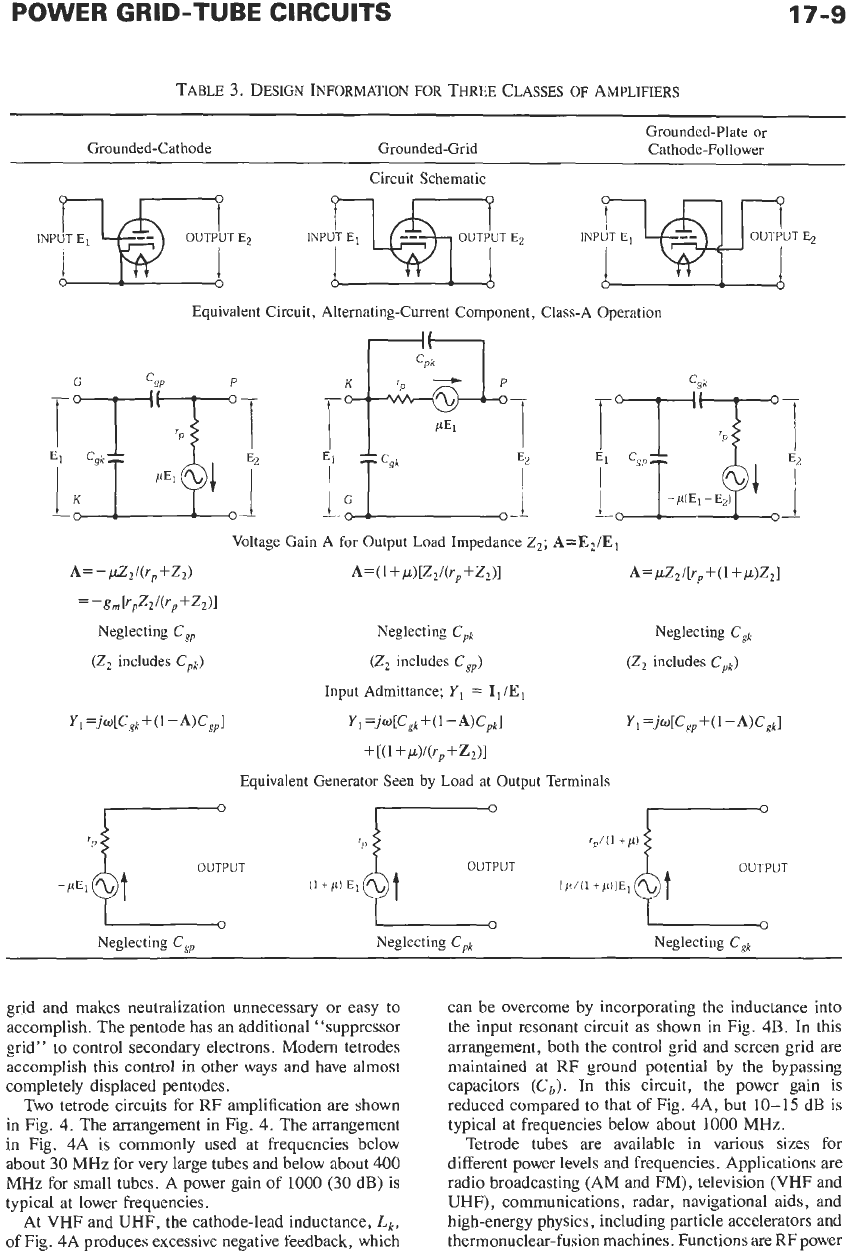
Design information for the first three classifications is
given
in
Table
3,
where
Z,
=
load impedance to which output terminals of
E,
=
phasor input voltage to amplifier,
E,
=
phasor output voltage across load impedance
amplifier are connected,
z2.
A
=
voltage gain of amplifier
=
E,/E,
,
Y,
=
input admittance to input terminals
of
amplifier,
o
=
2~
x
(frequency of excitation voltage
E,),
j
=
(-1)”2.
RF AMPLIFIER CIRCUITS
The power grid tube requires external circuits. Exam-
ples are shown schematically below for each kind of
tube.
Triodes
The triode has three electrodes: the thermionic cath-
ode, which emits electrons; the control grid; and the
anode, which collects most of the electrons. If the grid
is “biased” to a sufficiently high negative potential
(cutoff bias), no current flows.
As
the grid potential
becomes less negative, more current flows to the anode.
When the grid becomes positive with respect to the
cathode, both grid and anode draw current. At some
value of positive grid potential, the total space current
starts to exceed the emitting capability of the cathode
(cathode saturation) or the product of the grid current
and grid-cathode voltage (grid dissipation) exceeds the
limit above which the grid will emit electrons (primary
emission). Excessive grid dissipation interferes with the
desired operation of the tube or results in mechanical
distortion due
to
excessive temperature. There
is
also
a
limit to the power dissipation of the anode, depending
on the cooling method used.
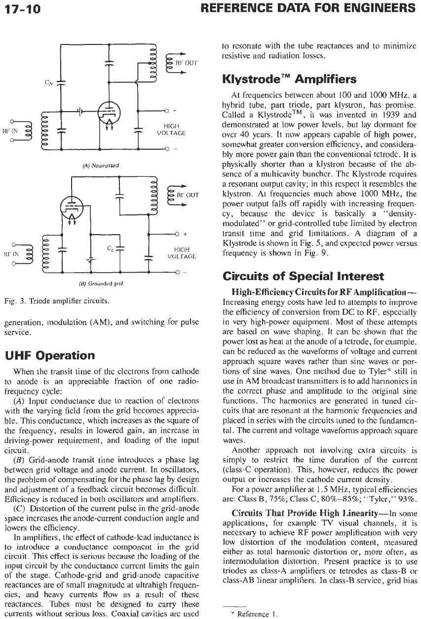
In
operation as an
RF
power amplifier, the triode
must be either “neutralized”
as
in Fig. 3A or operated
“grounded-grid” (“cathode-driven”) as
in
Fig.
3B;
otherwise, the internal capacitance between grid and
anode produces positive feedback that may cause self-
oscillation at a frequency close
to
the operating frequen-
cy. The triode may be operated as an efficient oscillator
by optimizing the feedback through the addition of
extra capacitance or by other means. Oscillators
are
used for RF heating of materials in industrial operations
where precise control of frequency is not required.
Small planar triodes are used at UHF and microwave
frequencies up to about 4 GHz, especially
in
pulse
service where peak-to-average power ratios are
100-
1000.
The anode supply voltage is typically
1
kV or
more.
Small cylindrical triodes are used mainly at
VHF
and
UHF where
CW
power of a few hundred watts or pulse
powers of tens
of
kilowatts are required. Modern triodes
are designed with beam-forming cathode and control-
grid geometry to allow the simplicity of design and
circuit advantages
of
a triode with the gain of
a
tetrode.
Tetrodes and Pentodes
The tetrode and pentode have four or five electrodes,
respectively.
A
tetrode has
a
cathode, a control grid,
a
screen grid, and an anode. The screen grid greatly
reduces the capacitance between the anode and control
POWER GRID-TUBE CIRCUITS
17-9
TABLE
3.
DESIGN
INFORMATION FOR
THREE
CLASSES
OF
AMPLIFIERS
Grounded-Plate or
Grounded-Cathode Grounded-Grid Cathode-Follower
Circuit Schematic
,Np!m
OUTPUT
E2
6
..
6
Equivalent Circuit, Alternating-Current Component, Class-A Operation
El
Voltage Gain
A
for
Output Load Impedance
Z,; A=E,/E,
A=-@
2
/
(rP+Z2) A=(l +PL)[Z~I@~+ZZ)I A=M2/[rp+(1 +P)Z21
=
-
8,
kPZ2
/(rp
+z,
)I
Neglecting
C,
Neglecting
Cpk
Neglecting
Cgk
(Z2
includes
Cgp)
Input Admittance;
Y,
=
Il/E1
Yi
=j4C8k
+
(1
-A)CpkI
(Z,
includes
Cpk)
(Z,
includes
Cpk)
Yl
=jw[Cgk+(1
-A)Cgpl
Yi
=.MCgp+(l
-A)Cg,I
+[(I
+P)~T~+ZZ)I
Equivalent Generator
Seen
by
Load
at
Output Terminals
grid and makes neutralization unnecessary or easy to
accomplish. The pentode has an additional “suppressor
grid”
to
control secondary electrons. Modern tetrodes
accomplish this control
in
other ways and have almost
completely displaced pentodes
.
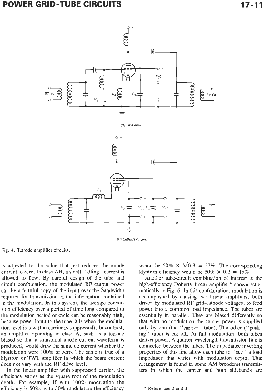
Two tetrode circuits for RF amplification are shown
in Fig. 4. The arrangement in Fig.
4.
The arrangement
in Fig.
4A
is commonly used at frequencies below
about
30
MHz for very large tubes and below about
400
MHz for small tubes.
A
power gain of
1000
(30
dB) is
typical at lower frequencies.
At VHF and UHF, the cathode-lead inductance,
L,,
of Fig. 4A produces excessive negative feedback, which
can be overcome by incorporating the inductance into
the input resonant circuit as shown
in
Fig. 4B.
In
this
arrangement, both the control grid and screen grid are
maintained at RF ground potential by the bypassing
capacitors
(Cb).
In
this circuit, the power gain is
reduced compared to that of Fig.
4A,
but
10-15
dB is
typical at frequencies below about
1000
MHz.
Tetrode tubes are available in various sizes for
different power levels and frequencies. Applications are
radio broadcasting (AM and FM), television (VHF and
UHF), communications, radar, navigational aids, and
high-energy physics, including particle accelerators and
thermonuclear-fusion machines. Functions are RF power
17-10
REFERENCE
DATA
FOR ENGINEERS
RF
OUT
E
(A)
Neutralized.
(E)
Groundedgrid
Fig.
3.
Triode amplifier circuits.
generation, modulation (AM), and switching for pulse
service.
UHF
Operation
When the transit time of the electrons from cathode
to anode is an appreciable fraction of one radio-
frequency cycle:
(A)
Input conductance due to reaction of electrons
with the varying field from the grid becomes apprecia-
ble. This conductance, which increases
as
the square of
the frequency, results in lowered gain,
an
increase in
driving-power requirement, and loading
of
the input
circuit.
(B)
Grid-anode transit time introduces
a
phase lag
between grid voltage and anode current.
In
oscillators,
the problem of compensating for the phase lag by design
and adjustment of
a
feedback circuit becomes difficult.
Efficiency is reduced in both oscillators and amplifiers.
(C)
Distortion of the current pulse in the grid-anode
space increases the anode-current conduction angle and
lowers the efficiency.
In
amplifiers, the effect of cathode-lead inductance is
to introduce a conductance component in the grid
circuit. This effect is serious because the loading
of
the
input circuit by the conductance current limits the gain
of
the stage. Cathode-grid and grid-anode capacitive
reactances are of small magnitude at ultrahigh frequen-
cies, and heavy currents flow
as
a result
of
these
reactances. Tubes must be designed to carry these
currents without serious
loss.
Coaxial cavities are used
to resonate with the tube reactances and
to
minimize
resistive and radiation losses.
Klystrode’“ Amplifiers
At frequencies between about
100
and
1000
MHz,
a
hybrid tube, part triode, part klystron, has promise.
Called
a
KlystrodeTM,
it
was invented in
1939
and
demonstrated at low power levels, but lay dormant for
over
40
years. It now appears capable of high power,
somewhat greater conversion efficiency, and considera-
bly more power gain than the conventional tetrode. It is
physically shorter than
a
klystron because of the ab-
sence of
a
multicavity buncher. The Klystrode requires
a
resonant output cavity; in this respect it resembles the
klystron. At frequencies much above
1000
MHz, the
power output falls
off
rapidly with increasing frequen-
cy, because the device is basically
a
“density-
modulated” or grid-controlled tube limited by electron
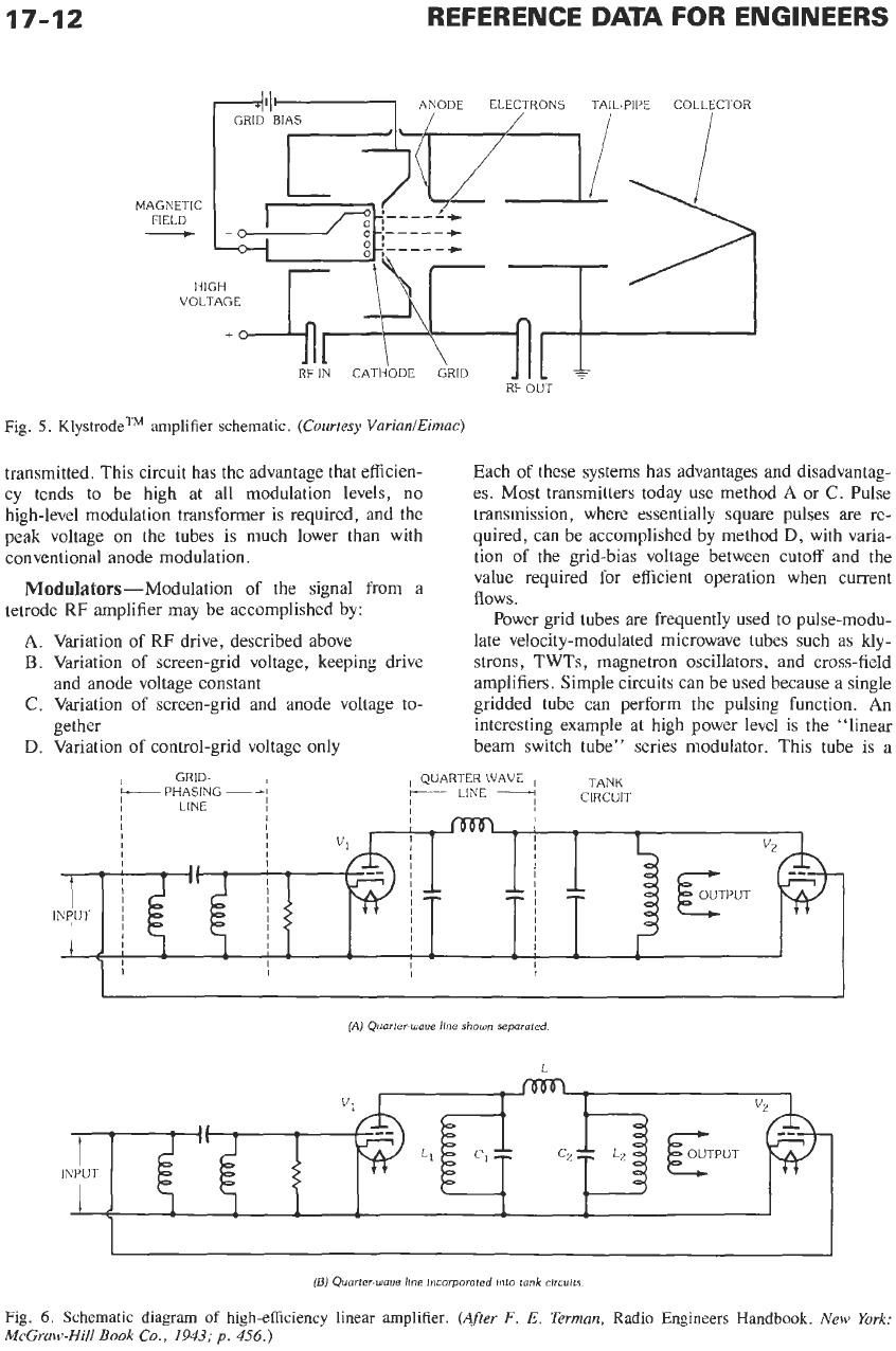
transit time and grid limitations. A diagram of
a
Klystrode is shown in Fig.
5,
and expected power versus
frequency is shown
in
Fig.
9.
Circuits of Special Interest
High-Efficiency Circuits
for
RF
Amplification-
Increasing energy costs have led to attempts to improve
the efficiency of conversion from DC to RF, especially
in very high-power equipment. Most
of
these attempts
are based
on
wave shaping. It can be shown that the
power lost as heat at the anode of
a
tetrode, for example,
can be reduced
as
the waveforms of voltage and current
approach square waves rather than sine waves or por-
tions of sine waves. One method due to Tyler‘’ still in
use
in
AM broadcast transmitters is to add harmonics in
the correct phase and amplitude to the original sine
functions. The harmonics are generated in tuned cir-
cuits that are resonant at the harmonic frequencies and
placed in series with the circuits tuned to the fundamen-
tal. The current and voltage waveforms approach square
waves.
Another approach not involving extra circuits
is
simply to restrict the time duration of the current
(class-C operation). This, however, reduces the power
output or increases the cathode current density.
For
a
power amplifier at
1.5
MHz, typical efficiencies
are: Class
B,
75%;
Class C,
80%-85%;
“Tyler,”
93%.
Circuits That Provide High Linearity-In
some
applications, for example
TV
visual channels, it
is
necessary to achieve
RF
power amplification with very
low distortion of the modulation content, measured
either
as
total harmonic distortion or, more often, as
intermodulation distortion. Present practice is to use
triodes
as
class-A amplifiers or tetrodes
as
class-B or
class-AB linear amplifiers. In class-B service, grid bias
*
Reference
1.
POWER GRID-TUBE CIRCUITS
17-11
(AI
Grid-driuen.
Fig.
4.
Tetrode amplifier circuits.
-
-
(5)
Cathode-driuen.
is
adjusted to the value that just reduces the anode
current to zero. In class-AB, a small “idling” current is
allowed to flow. By careful design of the tube and
circuit combination, the modulated
RF
output power
can be a faithful copy of the input over the bandwidth
required for transmission of the information contained
in the modulation. In this system, the average conver-
sion efficiency over a period of time long compared to
the modulation period or cycle can be reasonably high,
because power input to the tube falls when the modula-
tion level is low (the carrier is suppressed). In contrast,
an
amplifier operating in class
A,
such as a tetrode
biased
so
that a sinusoidal anode current waveform is
produced, would draw the same dc current whether the
modulation were
100%
or zero. The same is true of a
klystron or
TWT
amplifier in which the beam current
does not vary with the
RF
drive level.
In the linear amplifier with suppressed carrier, the
efficiency varies as the square root of the modulation
depth. For example, if with
100%
modulation the
efficiency
is
50%,
with
30%
modulation the efficiency
RF
OU1
E
would be
50%
X
a
=
27%.
The corresponding
klystron efficiency would be
50%
X
0.3
=
15%.
Another tube-circuit combination
of
interest is the
high-efficiency Doherty linear amplifier* shown sche-
matically in Fig.
6.
In this configuration, modulation
is
accomplished by causing two linear amplifiers, both
driven by modulated
RF
grid-cathode voltages, to feed
power into a common load impedance. The tubes are
essentially in parallel. They are biased differently
so
that with no modulation the carrier power is supplied
only by one (the “carrier” tube). The other (“peak-
ing” tube) is cut
off.
At full modulation, both tubes
deliver power. A quarter-wavelength transmission line
is
connected between the tubes. The impedance inverting
properties of this line allow each tube to “see” a load
impedance that varies with modulation depth. This
arrangement is found in some
AM
broadcast transmit-
ters in which the carrier and both sidebands are
*
References
2
and
3.
17-12
REFERENCE
DATA
FOR
ENGINEERS
Il1-I
ANODE ELECTRONS TAIL-PIPE COLLECTOR
GRID BIAS
/
/
I
/
RF OUT
MAGNETIC
FIELD
RFlN CATHODE GRID
/
Fig.
5.
KlystrodeTM amplifier schematic.
(Courtesy
VarianlEimac)
transmitted. This circuit has the advantage that efficien-
cy tends to be high at all modulation levels, no
high-level modulation transformer is required, and the
peak voltage on the tubes is much lower than with
conventional anode modulation.
Modulators-Modulation
of
the signal from a
tetrode
RF
amplifier may be accomplished by:
Each of these systems has advantages and disadvantag-
es. Most transmitters today use method
A
or
C.
Pulse
transmission, where essentially square pulses are re-
quired, can be accomplished by method
D,
with varia-
tion of the grid-bias voltage between cutoff and the
value required for efficient operation when current
flows.
Power grid tubes are freauentlv used
to
Dulse-modu-
-
1.
Variation of
RF
drive, described above
Variation
of
screen-grid voltage, keeping drive
and anode voltage constant
Variation
of
screen-grid and anode voltage to-
gether
Variation
of
control-grid voltage only
late velocity-modulated microwave tubes such as kly-
strons, TWTs, magnetron oscillators, and cross-field
amplifiers. Simple circuits can be used because a single
gridded tube can perform the pulsing function. An
interesting example at high power level is the “linear
beam switch tube” series modulator. This tube is a
A.
B.
C.
D.
I
GRID-
I
QUARTER~WAVE
I
TANK
-PHASING
-I
7
CIRCUIT
I
LINE
I
,
(A)
Quarter-wave
line
shown
separated.
L
(6)
Quarter-woue
line
incorporated
into
tank
clxutts
Fig.
6.
Schematic diagram
of
high-efficiency linear amplifier.
(After
F.
E.
Terman,
Radio Engineers Handbook.
New
York:
McGraw-Hill
Book
Co.,
1943;
p.
456.)
17-13
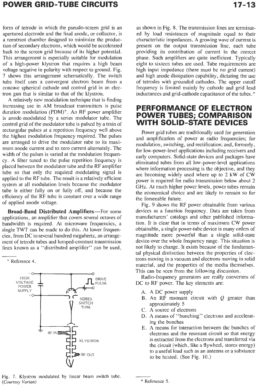
form of tetrode in which the pseudo-screen grid is an
apertured electrode and the final anode, or collector, is
a reentrant chamber designed to minimize the produc-
tion of secondary electrons, which would be accelerated
back to the screen grid because of its higher potential.
This arrangement is especially suitable for modulation
of a high-power klystron that requires a high beam
voltage negative in polarity with respect to ground. Fig.
7
shows this arrangement schematically. The switch
tube itself uses a convergent electron beam from a
concave spherical cathode and control grid in an elec-
tron gun that is similar to that of the klystron.
A relatively new modulation technique that is finding
increasing use in AM broadcast transmitters is pulse
duration modulation (PDM)”. An RF power amplifier
is anode-modulated by a series modulator tube. The
control grid of the modulator tube is pulsed by a train of
rectangular pulses at a repetition frequency well above
the highest modulation frequency required. The pulses
are arranged to drive the moduIator tube to its maxi-
mum anode current and to zero current alternately. The
width
of
the pulses is varied at the modulation frequen-
cy. A filter tuned to the pulse repetition frequency is
placed between the modulator tube and the RF amplifier
tube
so
that only the required modulating signal is
applied to the RF tube. The result is a relatively efficient
system at all modulation levels because the modulator
tube is either fully on or fully off, and because the
efficiency of the
RF
tube is constant over a wide range
of applied anode voltage.
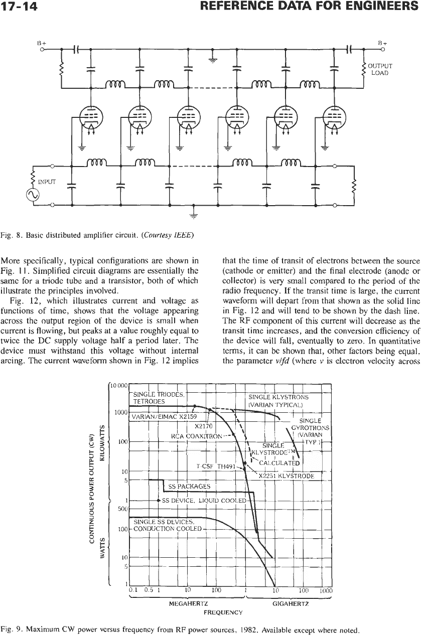
Broad-Band Distributed Amplifiers-For some
applications, an amplifier that covers several octaves of
bandwidth is required. At microwave frequencies, a
single TWT can be made to do this. At lower frequen-
cies, from DC to several hundred megahertz, an arrange-
ment of tetrode tubes and lumped-constant transmission
lines known as a “distributed amplifier” can be used,
*
Reference
4.
VOLTAGE
POWER
SUPPLY
SERIES
KLYSTRON
RF
OUT
Fig.
7.
Klystron modulated by linear beam switch tube.
(Courtesy
Varian)
as shown in Fig.
8.
The transmission lines are terminat-
ed by load resistances of magnitude equal to their
characteristic impedances. A growing wave of current is
present on the output transmission line, each tube
providing its contribution of current in the correct
phase. Such amplifiers are quite inefficient. Typically
eight to sixteen tubes are used. Tube requirements are
high input impedance (there must be no grid current)
and high anode dissipation capability, dictating the use
of tetrodes with grounded cathodes. The upper cutoff
frequency is limited mainly by cathode and grid lead
inductances and grid-cathode capacitance of the tubes.
*
PERFORMANCE OF ELECTRON
POWER TUBES; COMPARISON
WITH
SOLID-STATE DEVICES
Power grid tubes are traditionally used for generation
and amplification of power at radio frequencies; for
modulation, switching, and rectification; and, formerly,
for low-power-level applications including receivers and
early computers. Solid-state devices and packages have
eliminated tubes from all low-power-level applications
where information processing
is
the objective, and they
are becoming widely used where up to
2
kW of CW
power is required for radio transmission below about
2
GHz. At much higher power levels, power tubes remain
the economical choice and are likely to remain
so
for
the forseeable future.
Fig.
9
shows the RF power obtainable from various
devices as a function frequency. Data
are
taken from
manufacturers’ catalogs and other published informa-
tion. It is clear that in terms of maximum CW power
obtainable, a single power-tube device is many orders of
magnitude more powerful than a single solid-state
device over the whole frequency range. This situation is
not likely to change. It exists because of the fundamen-
tal physical distinction between the properties of elec-
trons moving in a vacuum and electrons moving in solid
material, and the properties of the media themselves.
This can be seen from the following discussion.
Radio-frequency generators are really converters of
DC to RF power. The key elements are:
A.
B.
C.
D.
E.
A DC power supply
An
RF
resonant circuit with
Q
greater than
approximately
5
A source of electrons
A
means of “bunching” electrons and accelerat-
ing the bunches
A means for interaction between the bunches of
electrons and the resonant circuit
so
that energy
is extracted from the electrons and transferred via
the circuit (which, like a flywheel, stores energy)
to a useful load such as an antenna or a substance
to be heated. (See Fig.
10.)
*
Reference
5.
17-14
REFERENCE
DATA
FOR ENGINEERS
Fig.
8
Basic
distributed amplifier circuit.
(Courtesy
ZEEE)
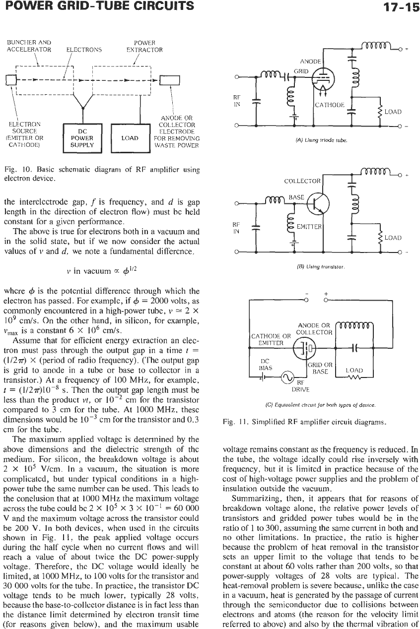
More specifically, typical configurations
are
shown in
Fig.
11.
Simplified circuit diagrams are essentially the
same for a triode tube and a transistor, both of which
illustrate the principles involved.
Fig.
12,
which illustrates current and voltage as
functions of time, shows that the voltage appearing
across the output region of the device is small when
current is flowing, but peaks at a value roughly equal to
twice the
DC
supply voltage half a period later. The
device must withstand this voltage without internal
arcing. The current waveform shown in Fig.
12
implies
that the time of transit of electrons between the source
(cathode or emitter) and the final electrode (anode or
collector) is very small compared to the period
of
the
radio frequency. If the transit time is large, the current
waveform will depart from that shown as the solid line
in Fig.
12
and will tend to be shown by the dash line.
The
RF
component of this current will decrease as the
transit time increases, and the conversion efficiency
of
the device will fall, eventually to zero.
In
quantitative
terms, it can be shown that, other factors being equal,
the parameter
vlfd
(where
v
is electron velocity across
Fig.
9.
Maximum
CW
power
versus
frequency from
RF
power
sources,
1982.
Available
except
where
noted.
17-15
--________
-1
ANODE OR
COLLECTOR
SOURCE ELECTRODE
FOR REMOVING
WASTE POWER
(EMITTER OR
CATHODE) SUPPLY
Fig.
10.
Basic schematic diagram
of
RF
amplifier using
electron device.
the interelectrode gap,
f
is frequency, and
d
is gap
length in the direction of electron flow) must be held
constant for
a
given performance.
The above is true for electrons both in
a
vacuum and
in the solid state, but if we now consider the actual
values of
v
and
d,
we note
a
fundamental difference,
v
in vacuum
4’’
where
#J
is the potential difference through which the
electron has passed. For example, if
#J
=
2000 volts,
as
commonly encountered
in
a
high-power tube,
v
=
2
X
lo9
cds. On the other hand, in silicon, for example,
v,,
is
a
constant 6
x
lo6
cds.
Assume that for efficient energy extraction
an
elec-
tron must pass through the output gap in
a
time
t
=
(1/271.)
X
(period of radio frequency). (The output gap
is grid to anode in
a
tube or base to collector in
a
transistor.) At a frequency
of
100
MHz,
for example,
t
=
(1/271.)10-*
s.
Then the output gap length must be
less than the product
vt,
or
lo-’
cm for the transistor
compared to
3
cm for the tube. At
1000
MHz,
these
dimensions would be cm for the transistor and
0.3
cm for the tube.
The maximum applied voltage
is
determined by the
above dimensions and the dielectric strength
of
the
medium. For silicon, the breakdown voltage is about
2
X
lo5
V/cm.
In
a
vacuum, the situation is more
complicated, but under typical conditions in
a
high-
power tube the same number can be used. This leads to
the conclusion that at
1000
MHz
the maximum voltage
across the tube could be
2
X
lo5
X
3
X
lo-’
=
60
000
V and the maximum voltage across the transistor could
be
200 V.
In
both devices, when used in the circuits
shown
in
Fig.
11,
the peak applied voltage occurs
during the half cycle when
no
current flows and will
reach
a
value
of
about twice the
DC
power-supply
voltage. Therefore, the
DC
voltage would ideally be
limited, at 1000
MHz,
to
100
volts for the transistor and
30
000
volts for the tube.
In
practice, the transistor
DC
voltage tends to be much lower, typically 28 volts,
because the base-to-collector distance is in fact less than
the distance limit determined by electron transit time
(for reasons given below), and the maximum usable
(AI
Using
triode
tube.
COLLECTOR
(E)
Using transistor
COLLECTOR
DRIVE
(C)
Equlualent
circuit
for
both types
ofdeuice.
Fig.
11.
Simplified RF amplifier circuit diagrams.
voltage remains constant
as
the frequency is reduced. In
the tube, the voltage ideally could rise inversely with
frequency, but it is limited in practice because of the
cost of high-voltage power supplies and the problem of
insulation outside the vacuum.
Summarizing, then, it appears that for reasons of
breakdown voltage alone, the relative power levels of
transistors and gridded power tubes would be in the
ratio of
1
to
300,
assuming the same current in both and
no other limitations. In practice, the ratio is higher
because the problem of heat removal
in
the transistor
sets an upper limit to the voltage that tends to be
constant at about 60 volts rather than 200 volts,
so
that
power-supply voltages of 28 volts are typical. The
heat-removal problem is severe because, unlike the case
in
a
vacuum, heat is generated by the passage of current
through the semiconductor due to collisions between
electrons and atoms (the reason for the velocity limit
referred to above) and
also
by the thermal vibration of