Moser A.P., Folkman S. Buried Pipe Design
Подождите немного. Документ загружается.

Tests on low stiffness ribbed steel pipe
Introduction.
Tests were performed on a ribbed steel pipe which has
been designed for use in the small diameter drainage pipe market.
The pipe is a smooth bore, helically ribbed pipe with essentially closed
ribs. Pipes tested are 18-, 24-, and 30-in diameters. A total of 10 tests
were conducted. The tests were run at Utah State University in the
small soil load cell (see Figs. 6.20 and 6.21). The pipe properti es are
as follows:
The Steel Sheet
Measured Modulus, Yield, lb/in
2
Tensile strength, lb/in
2
Gage thickness, in lb/in
2
Minimum Actual Minimum Actual
26 0.023 29.5 10
6
33,000 48,700 45,000 56,100
Description of pipes tested
1. The pipe is ribbed and is formed by helical winding with a lock-
seam.
2. The closed rib is 0.375 in tall for the 18- and 24-in pipes and 0.50-in
tall for the 30-in pipe. Three ribs are spaced over 5.43 in.
Steel and Ductile Iron Flexible Pipe Products 309
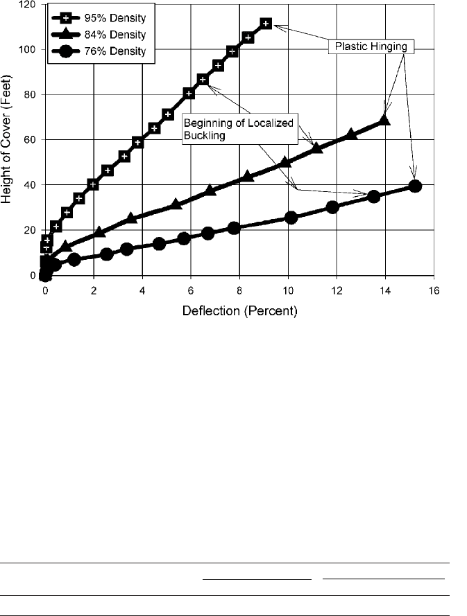
Figure 6.19 Vertical deflection for the three tests in silty-sand soil at various densities.
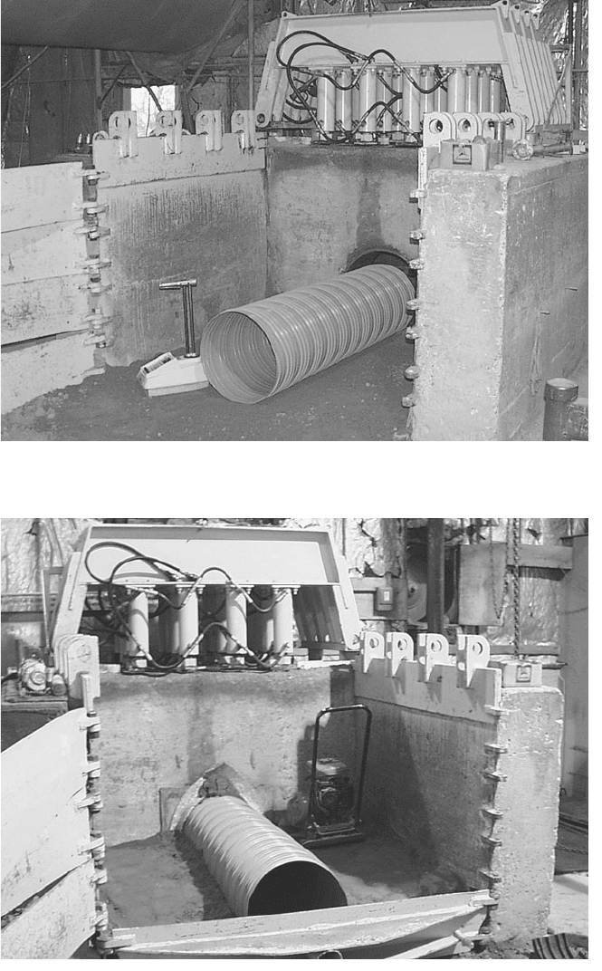
Figure 6.20 An 18-in ribbed pipe is being installed in small soil load cell at Utah State
University.
Figure 6.21 An 18-in ribbed pipe is being installed in small soil load cell at Utah State
University.
310
Sectional properties of the pipe are as follows:
30-in pipe 18- and 24-in pipes
Area per length A 0.230 in
2
/ft A 0.200 in
2
/ft
Moment of inertia I 0.550 in
4
/ft 10
3
I 0.261 in
4
/ft 10
3
Radius of gyration r 0.169 in r 0.125 in
The soil used for the tests was a silty sand. It was selected because of
the wide range of possible densities, which makes it ideal for pipe test-
ing. The soil gradation curve and the Proctor density curve for this soil
are given in Figs. 6.11 and 6.12, respectively.
Test results
Live load tests. The purpose of these tests was to simulate a loaded
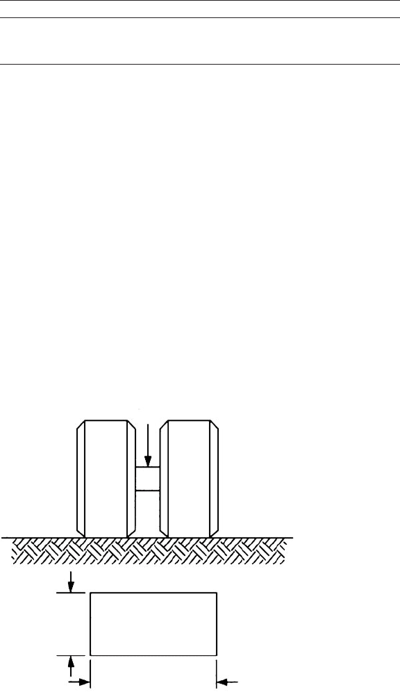
truck passing over the pipe. The standard AASHTO H-20 load repre-
sents a 16,000-lb load on a single dual-wheel assembly and distributed
over a 10-in 20-in area as shown in Fig. 6.22.
For low cover heights over the pipe, this test is very severe. These test
pipes were buried in silty-sand soil compacted to 90 percent standard
Proctor density. From the level of the top of the pipe to the upper-soil
surface, the soil was compacted to achieve as high a density as possible
to provide a compacted bearing surface for the 10 20-in plate.
The 18-in-diameter live load test. This test was conducted with only
1 ft of cover over the pipe to simulate a minimum cover application.
The load was first applied to the surface of the soil, but directly to the
Steel and Ductile Iron Flexible Pipe Products 311
16,000 lb
0.83 ft
(10 in)
1.67 ft (20 in)
Figure 6.22 H-20 live load schematic.
side of the pipe. This simulates an approaching truck. At 16,000 lb the
10-in 20-in plate penetrated the soil about 2 in. The pipe reaction
was a small inversion at the side of the pipe, as seen in Fig. 6.23. This
inversion is a precursor to the buckling seen in Fig. 6.24.
The loading plate was then positioned on the soil surface, just off the
centerline of the pipe, so the load is over one-half of the pipe. This is
the most critical position for a live load. The load was increased toward
the required 16,000 lb. At 14,000 lb, a soil failure wedge formed, the
plate began to penetrate the soil, and the pipe could not support the
resulting load. At this load, there was a catastrophic failure (buckling)
of the pipe (see Fig. 6.24). It is evident from the figure that the pipe
does not have enough longitudinal stiffness to transfer the load longi-
tudinally along the pipe.
The 24-in-diameter live load test. This test was also conducted with
only 1 ft of cover over the pipe to simulate a minimum cover applica-
tion. The load was first applied to the surface of the soil, but directly
to the side of the pipe. For this test, the loading plate was increased to
10-in 40-in—twice the area of the previous 18-in pipe. The decision
was made in view of the poor performance observed in that test and
because similar-sized plates had been used in evaluation of other types
of pipe. In general, the larger plate is justified because the longitudinal
312 Chapter Six
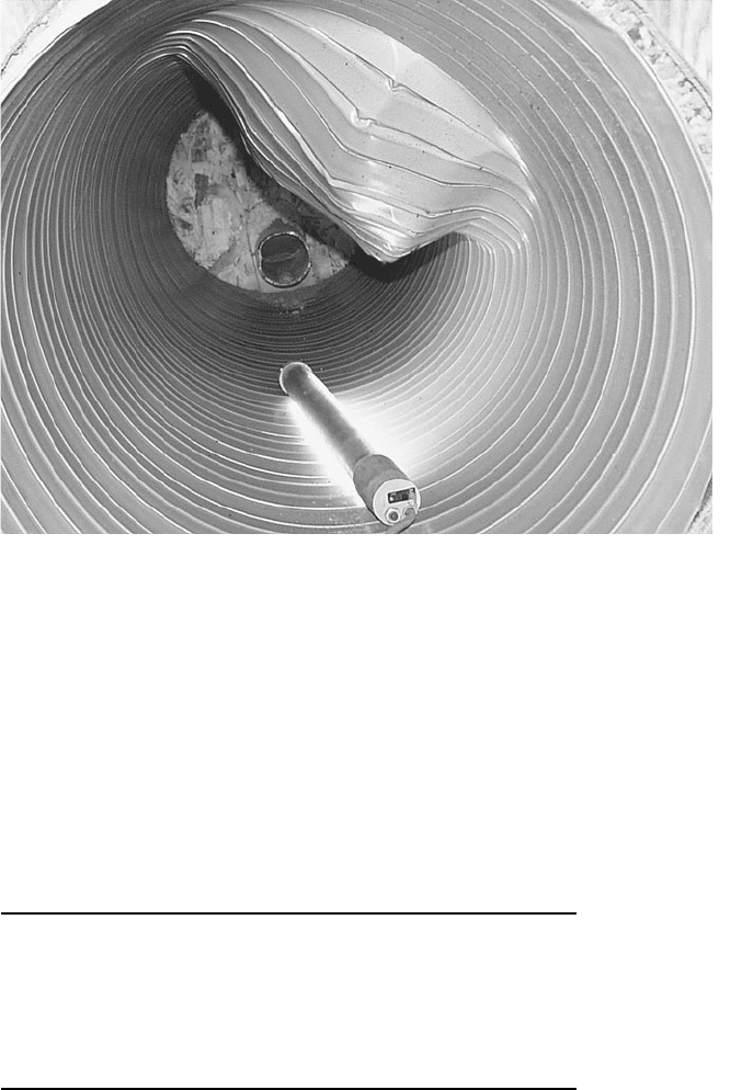
Figure 6.23 Small inversion in sidewall due to 16,000-lb live load adjacent to pipe. Pipe
installed with 1 ft of cover.
distribution of pressure through the soil in this test is more severe
than in the case of an actual pavement. Also, penetration into the soil
does not occur in a typical application. The loading plate penetrated
the soil about 1 in. The pipe showed no adverse reaction. This pipe was
more flexible than intended (see footnote to Table 6.3).
The loading plate was then positioned on the soil surface just off the
centerline of the pipe so the load is over one-half of the pipe. Again, this
is the most critical position for a live load. The load was increased
toward the required 16,000 lb. A soil failure wedge formed at 16,000 lb,
the plate began to penetrate the soil, and the pipe could not support
Steel and Ductile Iron Flexible Pipe Products 313
Figure 6.24 Buckling due to 14,000-lb live load over one-half of pipe.
TABLE 6.3 Summary of Soil Cell Results
Diameter, in3024
*
18
Rib depth, in
1
2
3
8
3
8
Wall thickness, intended, in 0.022 0.028 0.022
Wall thickness, measured, in 0.023 0.023 0.023
Fill height performance limit test 52 27 64
at 95 percent minimum density, ft
Fill height performance limit test 30 24 30
at 90 percent minimum density, ft
*
According to the manufacturer, the steel sheet used for the 24-in pipe was
thinner than intended (0.023 in instead of 0.028 in); hence, the pipe was
more flexible than would be permitted in practice.
the resulting load. At this load, there was a catastrophic failure (buck-
ling) of the pipe (see Figs. 6.25 and 6.26).
30-in-diameter live load test. This test was also conducted with only
1 ft of cover over the pipe to simulate a minimum cover application.
The load was first applied to the surface of the soil but directly to the
side of the pipe. Again, because of the catastrophic failure of the 18-in
pipe, the 16,000 lb was distributed over a 10-in 40-in area—twice
the area of the 18-in test. The loading plate penetrated the soil about
1 in. The pipe showed no adverse reaction.
The loading plate was then positioned on the soil surface just off the
centerline of the pipe (the most critical position for a live load), so
the load is over one-half of the pipe. The load was increased toward
the required 16,000 lb. At 16,000 lb, the plate penetrated the soil
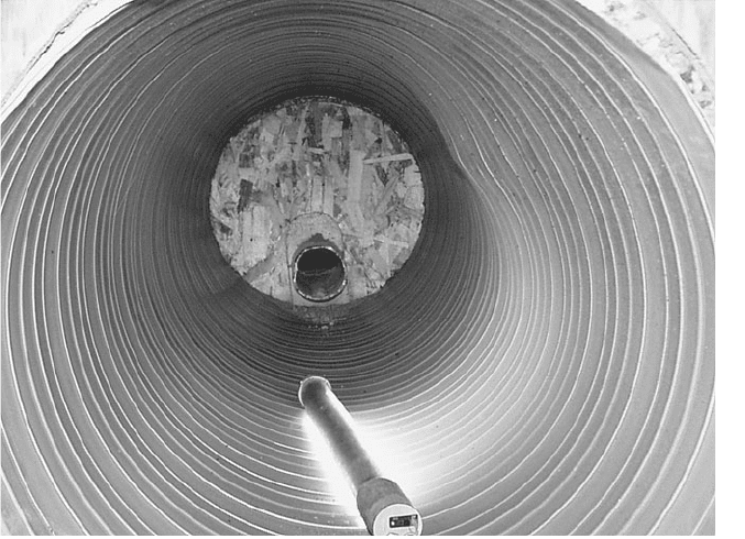
about 4 in and otherwise was in equilibrium (see Fig. 6.27). The load
was held for several minutes, and there was no adverse reaction of the
pipe (see Fig. 6.28). This pipe, when properly installed with cover
heights of 1 ft or greater, will withstand an H-20 loading.
The load was gradually increased to determine what load would
cause failure. At 18,853 lb, a soil failure wedge formed, the plate began
to penetrate the soil, and the pipe could not support the resulting load.
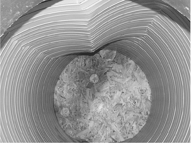
At this load, there was a catastrophic failure (buckling) of the pipe (see
Figs. 6.29 and 6.30).
314 Chapter Six
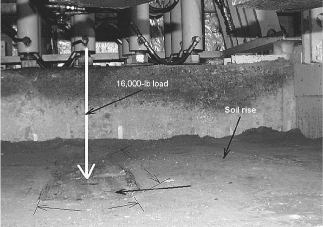
Figure 6.25 Photograph showing soil surface, plate penetration, and resulting soil rise
due to buckling of the pipe.
40 in
10 in
4 in penetration of
plate into soil
Steel and Ductile Iron Flexible Pipe Products 315
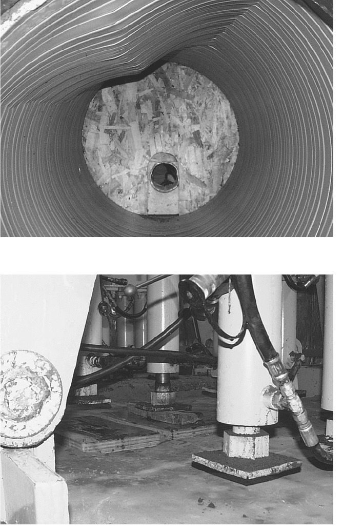
Figure 6.26 Buckled 24-in pipe resulting from a 16,000-lb live load.
Figure 6.27 Application of 16,000 lb.
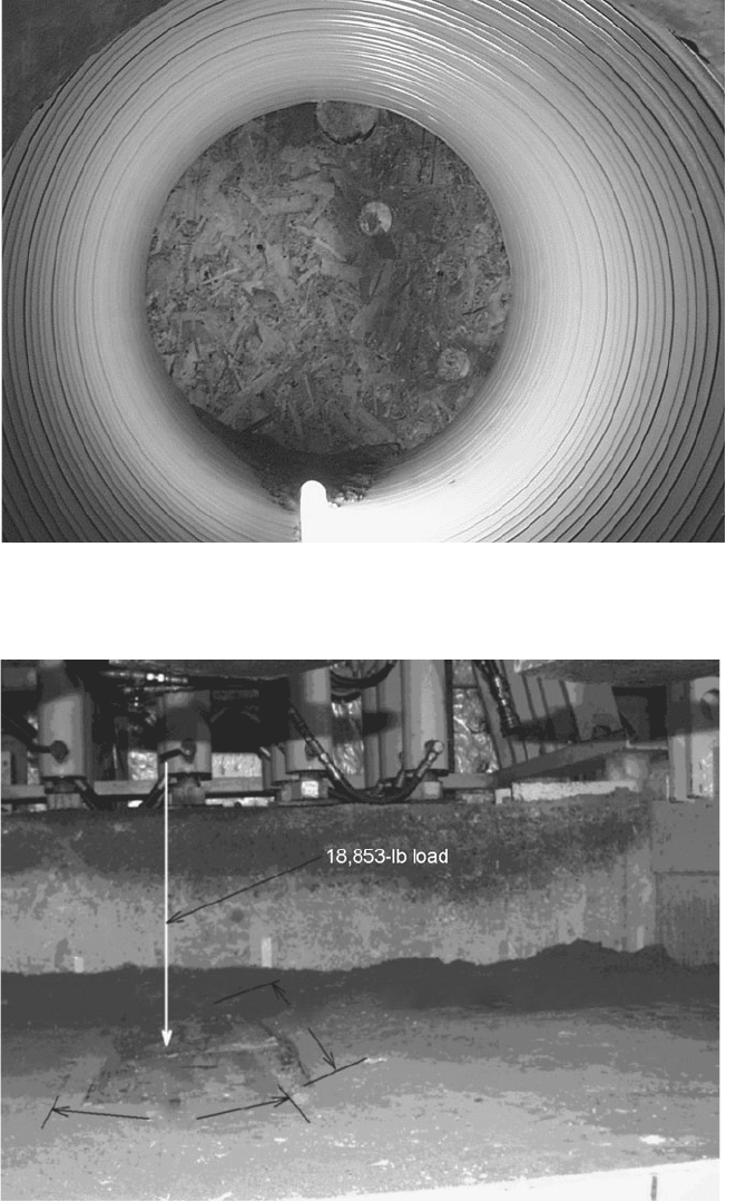
Figure 6.28 A 30-in pipe showing no negative reaction to a 16,000-lb live load.
Figure 6.29 Application of an 18,853-lb load.
40 in
30 in live load
10 in
316
Rerun of the 18-in-diameter live load test. Based on the experience
with the previous tests, this test was run with 2 ft of cover instead of
the 1 ft used for the other tests. Also, because of the 2 ft of cover, the
10-in 20-in plate was used to distribute the load. The load was first
applied to the surface of the soil, but directly to the side of the pipe. At
16,000 lb, the 10-in 20-in plate penetrated the soil about 3 in. The
pipe had no adverse reaction to the load.
The loading plate was then positioned on the soil surface just off the
centerline of the pipe (the most critical position for a live load), so the load
is over one-half of the pipe. The load was increased toward the required
16,000 lb. At 16,000 lb, the plate penetrated the soil about 4 in and oth-
erwise was in equilibrium. The load was held for several minutes, and
there was no adverse reaction of the pipe (see Figs. 6.31 and 6.32). This
pipe, when properly installed with 2 ft of cover, will withstand an H-20
loading.
Load-deflection tests. Six load-deflection tests were run on test pipes
buried in the small soil cell. There were three diameters (18-in, 24-in,
and 30-in) and two soil densities (90 and 95 percent standard Proctor).
In each test, vertical loading was increased until plastic hinging or
wall crushing was observed.
Steel and Ductile Iron Flexible Pipe Products 317
Figure 6.30 A 30-in pipe with buckled wall due to an 18,853-lb live load.
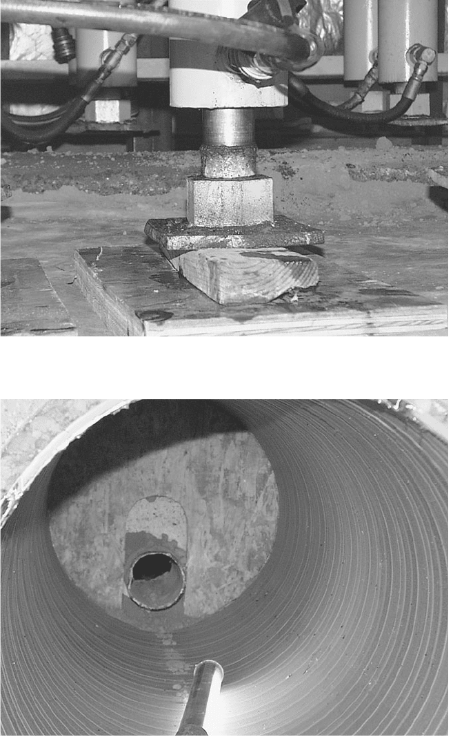
Figure 6.31 Photograph showing 16,000-lb load being applied to a 10-in 20-in plate
over one-half of the pipe.
Figure 6.32 A 24-in pipe, with 2 ft of cover, showing no adverse reaction to a 16,000-lb
live load.
318