Neamen D. Microelectronics: Circuit Analysis and Design
Подождите немного. Документ загружается.

1068 Part 2 Analog Electronics
Two-Pole High-Pass Butterworth Filter
To form a high-pass filter, the resistors and capacitors are interchanged from those
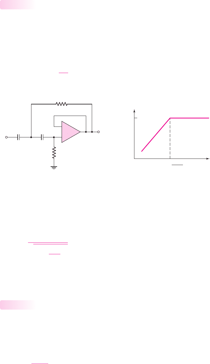
in the low-pass filter. A two-pole high-pass Butterworth filter is shown in Fig-
ure 15.8(a). The analysis proceeds exactly the same as in the last section, except
that the derivative is set equal to zero at
s = jω =∞
. Also, the two capacitors are
set equal to each other. The 3 dB or cutoff frequency can be written in the general
form
ω
3dB
= 2π f
3dB
=
1
RC
(15.22)
15.1.4
(a)
|T( j
w
)|
f
1
f
3dB
=
2pRC
1
+12 dB/
octave
or
+40 dB/
decade
(b)
V
i
V
o
R
3
= 0.707R
R
4
= 1.414R
CC
–
+
Figure 15.8 (a) Two-pole high-pass Butterworth filter and (b) Bode plot, transfer function
magnitude
We find that
R
3
= 0.707 R
and
R
4
= 1.414 R
. The magnitude of the voltage trans-
fer function for the two-pole high-pass Butterworth is
|T |=
1
1 +
f
3dB
f
4
(15.23)
The Bode plot of the transfer function magnitude for the two-pole high-pass
Butterworth filter is shown in Figure 15.8(b).
Higher-Order Butterworth Filters
The filter order is the number of poles and is usually dictated by the application
requirements. An N-pole active low-pass filter has a high-frequency rolloff rate of
N × 6
dB/octave. Similarly, the response of an N-pole high-pass filter increases at a
rate of
N × 6
dB/octave, up to the cutoff frequency. In each case, the 3 dB frequency
is defined as
f
3dB
=
1
2π RC
(15.24)
15.1.5
nea80644_ch15_1061-1140.qxd 07/12/2009 3:58 Page 1068 pinnacle MHDQ-New:MHDQ134:MHDQ134-15:
Chapter 15 Applications and Design of Integrated Circuits 1069
The magnitude of the voltage transfer function for a Butterworth Nth-order low-
pass filter is
|T |=
1
1 +
f
f
3dB
2N
(15.25)
For a Butterworth Nth-order high-pass filter, the voltage transfer function magnitude
is
|T |=
1
1 +
f
3dB
f
2N
(15.26)
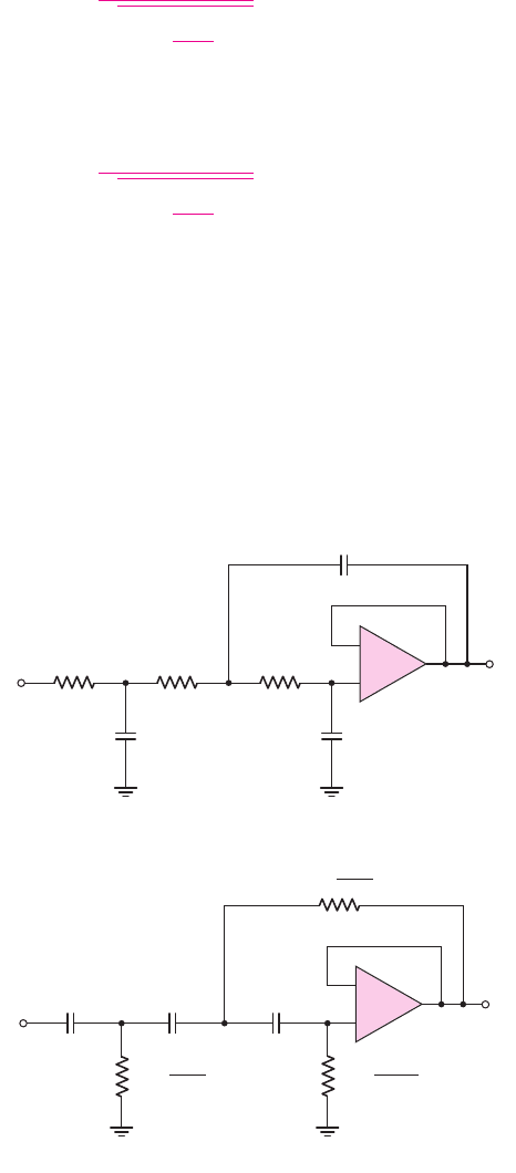
Figure 15.9(a) shows a three-pole low-pass Butterworth filter. The three resistors
are equal, and the relationship between the capacitors is found by taking the first and
second derivatives of the voltage gain magnitude with respect to frequency and set-
ting those derivatives equal to zero at
s = jω = 0
. Figure 15.9(b) shows a three-pole
high-pass Butterworth filter. In this case, the three capacitors are equal and the rela-
tionship between the resistors is also found through the derivatives.
Higher-order filters can be created by adding additional RC networks. However,
the loading effect on each additional RC circuit becomes more severe. The usefulness
of active filters is realized when two or more op-amp filter circuits are cascaded to
V
i
V
o
C
3
= 0.2024C
C
1
= 3.546C
C
2
= 1.392C
R
CCC
RR
V
i
V
o
R
1
=
R
3.546
R
3
=
R
0.2024
R
2
=
R
1.392
(a)
(b)
–
+
–
+
Figure 15.9 (a) Three-pole low-pass Butterworth filter and (b) three-pole high-pass
Butterworth filter
nea80644_ch15_1061-1140.qxd 07/12/2009 3:58 Page 1069 pinnacle MHDQ-New:MHDQ134:MHDQ134-15:
1070 Part 2 Analog Electronics
produce one large higher-order active filter. Because of the low output impedance of
the op-amp, there is virtually no loading effect between cascaded stages.
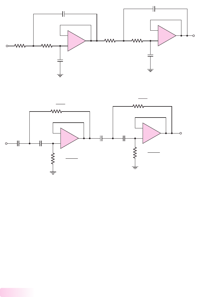
Figure 15.10(a) shows a four-pole low-pass Butterworth filter. The maximally flat
response of this filter is not obtained by simply cascading two two-pole filters. The rela-
tionship between the capacitors is found through the first three derivatives of the trans-
fer function. The four-pole high-pass Butterworth filter is shown in Figure 15.10(b).
Higher-order filters can be designed but are not considered here. Bandpass and
band-reject filters use similar circuit configurations.
Switched-Capacitor Filter
The results of Example 15.1 demonstrated that discrete resistors and capacitors may
be needed in active filters, since the required resistance and capacitance values are
too large to be conveniently fabricated on a monolithic IC chip. Large-value resistors
(
R > 10 k
) require a large chip area, and the absolute-value tolerance is difficult to
maintain. In addition, the maximum capacitance for a monolithic IC capacitor is
approximately 100 pF, which is also limited by the large chip area required and the
absolute-value tolerance. In these cases, accurate RC time constants may be difficult
to maintain.
15.1.6
V
o
V
i
C
3
= 2.613C
C
4
= 0.3825C
RR
C
1
= 1.082C
C
2
= 0.9241C
RR
+
–
V
o
V
i
CC
+
–
CC
R
1
=
R
1.082
R
3
=
R
2.613
R
4
=
R
0.3825
R
2
=
R
0.9241
(a)
(b)
–
+
–
+
–
+
–
+
Figure 15.10 (a) Four-pole low-pass Butterworth filter and (b) four-pole high-pass
Butterworth filter
nea80644_ch15_1061-1140.qxd 07/12/2009 3:58 Page 1070 pinnacle MHDQ-New:MHDQ134:MHDQ134-15:
Chapter 15 Applications and Design of Integrated Circuits 1071
Conventional active filters usually combine an IC op-amp and discrete resistors
and capacitors. However, even with discrete resistors and capacitors, standard com-
ponents may not be available for the design of a specific cutoff frequency. Design ac-
curacy for a specific cutoff frequency may therefore have to be sacrificed.
Switched-capacitor filters have the advantage of an all-IC circuit. The filter
uses small capacitance values and realizes large effective resistance values by using
a combination of capacitors and MOS switching transistors.
The Basic Principle of the Switched Capacitor
Figure 15.11 shows a simple circuit in which voltages
V
1
and
V
2
are applied at the
terminals of a resistance R. The current in the resistor is
I =
V
1
− V
2
R
(15.27(a))
The resistance is therefore
R =
V
1
− V
2
I
(15.27(b))
Since the current is the rate of charge flow, Equation (15.27(b)) states that the resis-
tance is a voltage difference divided by the rate of charge flow. We use this basic
definition in switched-capacitor circuits.
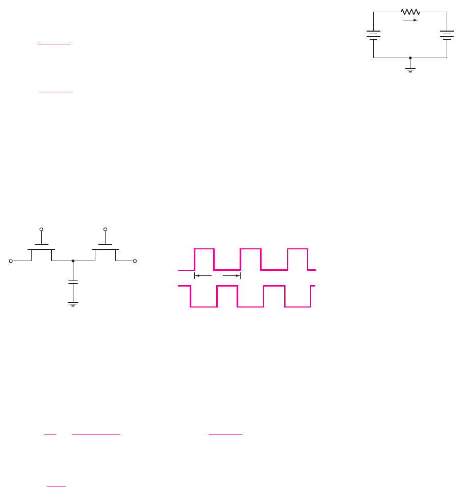
The circuit in Figure 15.12(a) consists of two MOSFETs and a capacitor. A two-
phase clock provides complementary but nonoverlapping
φ
1
and
φ
2
gate pulses, as
shown in Figure 15.12(b). When a clock pulse is high, the corresponding transistor
turns on; when the gate pulse is low, the transistor is off.
I
R
V
1
+
–
V
2
+
–
Figure 15.11 Voltages
applied to resistor terminals,
and the current
M
1
f
1
f
2
f
1
f
2
M
2
V
1
V
2
C
T
C
(a) (b)
Figure 15.12 (a) Capacitor with two switching MOSFETs and (b) two-phase clock pulses
When
φ
1
goes high,
M
1
turns on and capacitor C charges up to
V
1
. When
φ
2
goes
high,
M
2
turns on and capacitor C discharges to
V
2
(assuming
V
1
> V
2
). The amount
of charge transferred during this process is
Q = C(V
1
− V
2
)
and the transfer occurs
during one clock period
T
C
. The equivalent current is then
I
eq
=
Q
T
C
=
C(V
1
− V
2
)
T
C
= f
C
C(V
1
− V
2
) =
V
1
− V
2
R
eq
(15.28)
where
f
C
is the clock frequency and
R
eq
is the equivalent resistance given by
R
eq
=
1
f
C
C
(15.29)
nea80644_ch15_1061-1140.qxd 07/12/2009 3:58 Page 1071 pinnacle MHDQ-New:MHDQ134:MHDQ134-15:

1072 Part 2 Analog Electronics
Using this technique, we can simulate an equivalent resistance by alternately
charging and discharging a capacitor between two voltage levels. A large equivalent
resistance can be simulated by using a small capacitance and an appropriate clock fre-
quency. The circuit in Figure 15.12(a) is therefore called a switched-capacitor circuit.
EXAMPLE 15.2
Objective: Determine the clock frequency required to simulate a specific resistance.
Consider the switched-capacitor circuit in Figure 15.12(a). Assume a capaci-
tance of
C = 20 pF
. Determine the clock frequency required to simulate a 1 M
resistance.
Solution: From Equation (15.29), we find that
f
C
=
1
CR
eq
=
1
(20 × 10
−12
)(10
6
)
⇒ 50 kHz
Comment: A very large resistance can be readily simulated by a small capacitance
and a reasonable clock frequency.
EXERCISE PROBLEM
Ex 15.2: Consider the switched-capacitor circuit in Figure 15.12(a). (a) If the
clock frequency is
f
C
= 100
kHz and
C = 1.2
pF, what is the value of the simu-
lated resistance? (b) A
50
M
resistor is to be simulated using a clock frequency
of
f
C
= 50
kHz. What is the required value of capacitor? (Ans. (a)
R
eq
= 8.33
M
,
(b)
C = 0.4
pF)
Various classes of active filters, such as low-pass, high-pass, bandpass, and
band-reject circuits, can be implemented by the switched-capacitor technique, which
then results in an all-capacitor filter circuit.
Example of Switched-Capacitor Filter
Consider the one-pole low-pass filter in Figure 15.13(a). The transfer function is
T (s) =
V
o
(s)
V
in
(s)
=−
R
F
R
1
1
1 + sR
F
C
F
(15.30)
v
in
v
o
R
F
C
F
R
1
(a)
–
+
f
1
f
2
f
1
f
2
v
in
v
o
C
F
C
1
C
2
(b)
–
+
Figure 15.13 (a) One-pole low-pass filter and (b) equivalent switched-capacitor circuit
nea80644_ch15_1061-1140.qxd 07/12/2009 3:58 Page 1072 pinnacle MHDQ-New:MHDQ134:MHDQ134-15:

Chapter 15 Applications and Design of Integrated Circuits 1073
and the cutoff frequency is
f
3dB
=
1
2π R
F
C
F
(15.31)
If a 10 kHz cutoff frequency is required and if
C
F
= 10 pF
, then the
R
F
resistance
required is approximately 1.6 M
. In addition, if a gain of
−10
is desired, then re-
sistance
R
1
must be 160 k
.
The equivalent switched-capacitor filter is shown in Figure 15.13(b). The
transfer function is still given by Equation (15.30), where
R
Feq
= 1/( f
C
C
2
)
and
R
1eq
= 1/( f
C
C
1
)
. The transfer function is then
T ( jω) =−
(1/f
C
C
2
)
(1/f
C
C
1
)
·
1
1 + j
(2π f )C
F
f
C
C
2
=−
C
1
C
2
·
1
1 + j
f
f
3dB
(15.32)
The low-frequency gain is
−C
1
/C
2
, which is just the ratio of two capacitances,
and the 3 dB frequency is
f
3dB
= ( f
C
C
2
)/(2πC
F
)
which is also proportional to the ratio of two other capacitances. For MOS IC ca-
pacitance values of approximately 10 pF, the ratio tolerance is on the order of 0.1
percent. This means that switched-capacitor filter characteristics can be precisely
controlled.
DESIGN EXAMPLE 15.3
Objective: Design a one-pole low-pass switched capacitor filter to meet a set of
specifications.
Specifications: The circuit with the configuration shown in Figure 15.13(b) is to
be designed such that the low-frequency gain is
−1
and the cutoff frequency is
1 kHz.
Choices: An ideal op-amp is available and standard-valued capacitors are to be used.
Solution: From Equation (15.32), the low-frequency gain is
−(C
1
/C
2
)
, and the ca-
pacitance ratio must be
(C
1
/C
2
) = 1
. From Equation (15.32), the cutoff frequency is
f
3dB
=
f
C
C
2
2πC
F
If we set the clock frequency to
f
C
= 10 kHz
, then
C
2
C
F
=
2π f
3dB
f
C
=
2π(10
3
)
10 × 10
3
= 0.628
Trade-offs: We can use standard-valued capacitors
C
1
= C
2
= 75 pF
. We would
need
C
F
= C
2
/0.628 = 75/0.628 = 119.4pF
. A standard-valued capacitor
C
F
=
120 pF can be used.
Comment: Since the low-frequency gain and cutoff frequency are both functions of
capacitor ratios, the absolute capacitor values can be designed for compatibility with
IC fabrication.
nea80644_ch15_1061-1140.qxd 07/12/2009 3:58 Page 1073 pinnacle MHDQ-New:MHDQ134:MHDQ134-15:

1074 Part 2 Analog Electronics
EXERCISE PROBLEM
Ex 15.3: For the switched-capacitor circuit in Figure 15.13(b), the parameters
are:
C
1
= 30 pF
,
C
2
= 5pF
, and
C
F
= 12 pF
. The clock frequency is 100 kHz.
Determine the low-frequency gain and the cutoff frequency. (Ans.
−C
1
/C
2
=
−6
,
f
3dB
= 6.63 kHz
)
This discussion of switched-capacitor filters is a short introduction to the topic
and is intended only to show another application of operational amplifiers. Switched-
capacitor filters are “sampled-data systems”; that is, the analog input signal is not
transmitted through the circuit as a continuous signal but passes through the system
as a series of pulses. The equivalent resistance given by Equation (15.29) is valid
only for clock frequencies much greater than the analog input signal frequency.
Switched-capacitor systems can be analyzed and designed by z-transform techniques.
Test Your Understanding
TYU 15.1 (a) Design a three-pole high-pass Butterworth active filter with a cutoff
frequency of 200 Hz and a unity gain at high frequency. (b) Using the results of part (a),
determine the magnitude of the voltage transfer function at (i)
f = 100
Hz and
(ii)
f = 300
Hz. (Ans. (a) Let
C = 0.01 μ
F, then
R
1
= 22.44
k
,
R
2
= 57.17
k
,
R
3
= 393.2
k
; (b) (i)
|
T
|
= 0.124 →−18.1
dB, (ii)
|
T
|
= 0.959 →−0.365
dB)
TYU 15.2 (a) Design a four-pole low-pass Butterworth active filter with a 3 dB fre-
quency of 30 kHz. (b) Determine the frequency at which the voltage transfer function
magnitude is 99 percent of its maximum value. (Ans. (a) Let
R = 100
k
, then
C
1
= 57.4
pF,
C
2
= 49.02
pF,
C
3
= 138.6
pF,
C
4
= 20.29
pF; (b)
f = 18.43
kHz)
TYU 15.3 One-, two-, three-, and four-pole low-pass Butterworth active filters are
all designed with a cutoff frequency of 10 kHz and unity gain at low frequency. De-
termine the voltage transfer function magnitude, in dB, at 12 kHz for each filter.
(Ans.
−3.87
dB,
−4.88
dB,
−6.0
dB, and
−7.24
dB)
TYU 15.4 Simulate a 25 M
resistance using the circuit in Figure 15.12(a). What
capacitor value and clock frequency are required? (Ans. For example, for
f
C
= 50
kHz, then
C = 0.8
pF)
15.2 OSCILLATORS
Objective: • Analyze and design oscillators that provide sinusoidal
signals at specified frequencies.
In this section, we will look at the basic principles of sine-wave oscillators. In our study
of feedback in Chapter 12, we emphasized the need for negative feedback to provide a
stable circuit. Oscillators, however, use positive feedback and, therefore, are actually
nonlinear circuits in some cases. The analysis and design of oscillator circuits are di-
vided into two parts. In the first part, the condition and frequency for oscillation are
determined; in the second part, means for amplitude control is addressed. We consider
only the first step in this section to gain insight into the basic operation of oscillators.
nea80644_ch15_1061-1140.qxd 07/12/2009 3:58 Page 1074 pinnacle MHDQ-New:MHDQ134:MHDQ134-15:
Chapter 15 Applications and Design of Integrated Circuits 1075
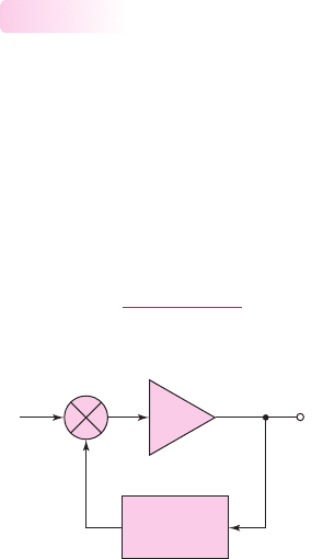
Basic Principles for Oscillation
The basic oscillator consists of an amplifier and a frequency-selective network
connected in a feedback loop. Figure 15.14 shows a block diagram of the fundamen-
tal feedback circuit, in which we are implicitly assuming that negative feedback is
employed. Although actual oscillator circuits do not have an input signal, we initially
include one here to help in the analysis. In previous feedback circuits, we assumed
the feedback transfer function
β
was independent of frequency. In oscillator circuits,
however,
β
is the principal portion of the loop gain that is dependent on frequency.
For the circuit shown, the ideal closed-loop transfer function is given by
A
f
(s) =
A(s)
1 + A(s)β(s)
(15.33)
15.2.1
+
–
Frequency
selective
network, b
v
s
v
e
v
o
A
v
fb
Figure 15.14 Block diagram of the fundamental feedback circuit
and the loop gain of the feedback circuit is
T (s) = A(s)β(s)
(15.34)
From our discussion of feedback in Chapter 12, we know that the loop gain T(s)
is positive for negative feedback, which means that the feedback signal
v
fb
subtracts
from the input signal
v
s
. If the loop gain T(s) becomes negative, then the feedback
signal phase causes
v
fb
to add to the input signal, increasing the error signal
v
ε
. If
T (s) =−1
, the closed-loop transfer function goes to infinity, which means that the
circuit can have a finite output for a zero input signal.
As T(s) approaches
−1
, an actual circuit becomes nonlinear, which means that
the gain does not go to infinity. Assume that
T (s) ≈−1
so that positive feedback
exists over a particular frequency range. If a spontaneous signal (due to noise) is cre-
ated at
v
s
in this frequency range, the resulting feedback signal
v
fb
is in phase with
v
s
, and the error signal
v
ε
is reinforced and increased. This reinforcement process
continues at only those frequencies for which the total phase shift around the feed-
back loop is zero. Therefore, the condition for oscillation is that, at a specific fre-
quency, we have
T ( jω
o
) = A( jω
o
)β( jω
o
) =−1
(15.35)
The condition that
T ( jω
o
) =−1
is called the Barkhausen criterion.
Equation (15.35) shows that two conditions must be satisfied to sustain
oscillation:
1. The total phase shift through the amplifier and feedback network must be
N × 360
◦
, where
N = 0
,1,2,. . . .
2. The magnitude of the loop gain must be unity.
nea80644_ch15_1061-1140.qxd 07/12/2009 3:58 Page 1075 pinnacle MHDQ-New:MHDQ134:MHDQ134-15:
1076 Part 2 Analog Electronics
In the feedback circuit block diagram in Figure 15.14, we implicitly assume
negative feedback. For an oscillator, the feedback transfer function, or the frequency-
selective network, must introduce an additional 180 degree phase shift such that the
net phase around the entire loop is zero. For the circuit to oscillate at a single fre-
quency
ω
o
, the condition for oscillation, from Equation (15.35), should be satisfied at
only that one frequency.
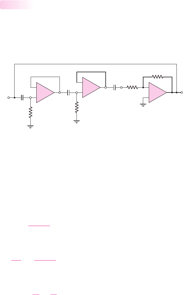
Phase-Shift Oscillator
An example of an op-amp oscillator is the phase-shift oscillator. One configuration
of this oscillator circuit is shown in Figure 15.15. The basic amplifier of the circuit is
the op-amp
A
3
, which is connected as an inverting amplifier with its output con-
nected to a three-stage RC filter. The voltage followers in the circuit eliminate load-
ing effects between each RC filter stage.
15.2.2
(v
I
)
C
C
C
v
O
v
1
v
1
v
2
v
2
v
3
R
2
R
R
R
A
1
–
+
A
2
–
+
A
3
–
+
Figure 15.15 Phase-shift oscillator circuit with voltage-follower buffer stages
The inverting amplifier introduces a
−180
degree phase shift, which means that
each RC network must provide 60 degrees of phase shift to produce the 180 degrees
required of the frequency-sensitive feedback network in order to produce positive
feedback. Note that the inverting terminal of op-amp
A
3
is at virtual ground; there-
fore, the RC network between op-amps
A
2
and
A
3
functions exactly as the other two
RC networks. We assume that the frequency effects of the op-amps themselves occur
at much higher frequencies than the response due to the RC networks. Also, to aid in
the analysis, we assume an input signal (
v
I
) exists at one node as shown in the figure.
The transfer function of the first RC network is
v
1
=
sRC
1 + sRC
(v
I
)
(15.36)
Since the RC networks are assumed to be identical, and since there is no loading
effect of one RC stage on another, we have
v
3
(v
I
)
=
sRC
1 + sRC
3
= β(s)
(15.37)
where
β(s)
is the feedback transfer function. The amplifier gain A(s) in Equa-
tion (15.33) and (15.34) is actually the magnitude of the gain, or
A(s) =
v
O
v
3
=
R
2
R
(15.38)
nea80644_ch15_1061-1140.qxd 07/12/2009 3:58 Page 1076 pinnacle MHDQ-New:MHDQ134:MHDQ134-15:

Chapter 15 Applications and Design of Integrated Circuits 1077
The loop gain is then
T (s) = A(s)β(s) =
R
2
R
sRC
1 + sRC
3
(15.39)
From Equation (15.35), the condition for oscillation is that
|T ( jω
o
)|=1
and the
phase of
T ( jω
o
)
must be 180 degrees. When these requirements are satisfied, then
v
O
will equal (
v
I
) and a separate input signal will not be required.
If we set
s = jω
, Equation (15.39) becomes
T ( jω) =
R
2
R
( jωRC)
3
(1 + jωRC)
3
=−
R
2
R
( jωRC)(ωRC)
2
[1 − 3ω
2
R
2
C
2
] + jωRC[3 −ω
2
R
2
C
2
]
(15.40)
To satisfy the condition
T ( jω
o
) =−1
, the imaginary component of Equation (15.40)
must equal zero. Since the numerator is purely imaginary, the denominator must
become purely imaginary, or
1 − 3ω
2
o
R
2
C
2
= 0
which yields
ω
o
=
1
√
3RC
(15.41)
where
ω
o
is the oscillation frequency. At this frequency, Equation (15.40) becomes
T ( jω
o
) =−
R
2
R
( j/
√
3)(1/3)
0 + ( j/
√
3)[3 − (1/3)]
=−
R
2
R
1
8
(15.42)
Consequently, the condition
T ( jω
o
) =−1
is satisfied when
R
2
R
= 8
(15.43)
Equation (15.43) implies that if the magnitude of the inverting amplifier gain is
greater than 8, the circuit will spontaneously begin oscillating and will sustain
oscillation.
EXAMPLE 15.4
Objective: Determine the oscillation frequency and required amplifier gain for a
phase-shift oscillator.
Consider the phase-shift oscillator in Figure 15.15 with parameters
C = 0.1 μF
and
R = 1k
.
Solution: From Equation (15.41), the oscillation frequency is
f
o
=
1
2π
√
3RC
=
1
2π
√
3(10
3
)(0.1 × 10
−6
)
= 919 Hz
The minimum amplifier gain magnitude is 8 from Equation 15.43; therefore, the
minimum value of
R
2
is 8 k
.
Comment: Higher oscillation frequencies can easily be obtained by using smaller
capacitor values.
nea80644_ch15_1061-1140.qxd 07/12/2009 3:58 Page 1077 pinnacle MHDQ-New:MHDQ134:MHDQ134-15: