Neamen D. Microelectronics: Circuit Analysis and Design
Подождите немного. Документ загружается.


1098 Part 2 Analog Electronics
Consider the oscillator in Figure 15.35. Design the circuit to oscillate at
f
o
= 1 kHz
.
Solution: Using Equation (15.88), we can write
R
X
C
X
=
1
2.2 f
o
=
1
2.2(10
3
)
= 4.55 ×10
−4
If
C
X
= 0.1 μF
, then
R
X
= 4.55 k
.
Trade-offs: Using standard-valued elements with values of
C
X
= 0.082 μF
and
R
X
= 5.6k
produces an oscillation frequency of 990 Hz, within 1% of the speci-
fied value. If element tolerance values are taken into account, a potentiometer may
have to be used to produce the 1000 Hz oscillation frequency.
Comment: A larger frequency of oscillation can easily be obtained by using a
smaller capacitor value.
EXERCISE PROBLEM
*Ex 15.8: For the Schmitt trigger oscillator in Figure 15.35, the saturation out-
put voltages are
+10
V and
−5V
.
R
1
= R
2
= 20 k
,
R
X
= 50 k
, and
C
X
=
0.01 μF
. Determine the frequency of oscillation and the duty cycle. Sketch
v
O
and
v
X
versus time over two periods of the oscillation. (Ans.
f = 866 Hz
,duty
cycle
= 39.7%
)
Monostable Multivibrator
A monostable multivibrator has one stable state, in which it can remain indefinitely
if not disturbed. However, a trigger pulse can force the circuit into a quasi-stable state
for a definite time, producing an output pulse with a particular height and width. The
circuit then returns to its stable state until another trigger pulse is applied. The mono-
stable multivibrator is also called a one-shot.
A monostable multivibrator is created by modifying the Schmitt trigger oscilla-
tor as shown in Figure 15.37. A clamping diode
D
1
is connected in parallel with
C
X
.
In the stable state, the output is high and voltage
v
X
is held low by the conducting
diode
D
1
.
15.4.2
R
X
v
X
C
X
D
1
R
3
R
2
R
1
D
2
D
Z1
D
Z2
C
v
Y
v
O
v
I
–
+
Figure 15.37 Schmitt trigger monostable multivibrator
nea80644_ch15_1061-1140.qxd 07/12/2009 3:58 Page 1098 pinnacle MHDQ-New:MHDQ134:MHDQ134-15:

Chapter 15 Applications and Design of Integrated Circuits 1099
The trigger circuit is composed of the capacitor
C
, resistor
R
3
, and diode
D
2
,
and is connected to the noninverting terminal of the comparator. The value of
R
3
is
chosen to be much larger than
R
1
, so that voltage
v
Y
is determined primarily by a
voltage divider of
R
1
and
R
2
. We then have
v
Y
∼
=
R
1
R
1
+ R
2
V
P
≡ β V
P
(15.89)
where
V
P
is the sum of the forward and breakdown voltages of
D
Z1
and
D
Z2
,or
V
P
= (V
γ 1
+ V
Z2
)
. This voltage is the positive saturated output voltage.
The circuit is triggered by a negative-going step voltage applied to capacitor
C
.
This action forward-biases diode
D
2
and pulls the voltage
v
Y
below
v
X
. Since the
comparator then sees a larger voltage at the inverting terminal, the output switches to
its low state of
v
O
=−V
P
=−(V
γ 2
+ V
Z1
)
Voltage
v
Y
then becomes
v
Y
∼
=
−
R
1
R
1
+ R
2
V
P
≡−βV
P
(15.90)
causing
D
2
to become reverse biased, thus isolating the oscillator circuit from the
input triggering network. The negative-step change in
v
O
causes voltage
v
X
to de-
crease exponentially with a time constant of
τ
x
= R
X
C
X
toward a final value of
−V
P
. Diode
D
1
is reverse biased during this time. When
v
X
drops just below the
value of
v
Y
given by Equation (15.90), the output switches back to its positive satu-
rated value of
+V
P
. The capacitor voltage
v
X
then starts to increase exponentially
toward a final value of
+V
P
. When
v
X
reaches
V
γ
, diode
D
1
again becomes forward
biased,
v
X
is clamped at
V
γ
, and the output remains in its high state.
The waveforms of
v
O
and
v
X
versus time are shown in Figure 15.38. After the
output has switched back to its high state, the capacitor voltage
v
X
must return to its
quiescent value of
v
X
= V
γ
. This implies that there is a recovery time of
(T
− T )
during which the circuit should not be retriggered.
For
t > 0
, voltage
v
X
can be written in the same general form as Equation (15.82),
as follows:
v
X
=−V
P
+(V
γ
−(−V
P
))e
−t/τ
x
(15.91)
v
I
t
0
v
X
t
T
0 T ′
V
g
V
g
Toward
–V
P
Toward
+V
P
v
O
t
–V
P
+V
P
0
T
(a)
(b) (c)
Figure 15.38 Schmitt trigger monostable multivibrator voltages versus time (a) input trigger
pulse, (b) capacitor voltage, and (c) output pulse
nea80644_ch15_1061-1140.qxd 07/12/2009 3:58 Page 1099 pinnacle MHDQ-New:MHDQ134:MHDQ134-15:

1100 Part 2 Analog Electronics
where
τ
x
= R
X
C
X
. At
t = T
,
v
X
=−βV
P
and the output switches high. The pulse
width is then
T = τ
x
ln
1 + (V
γ
/V
P
)
(1 − β)
(15.92)
If we assume
V
γ
V
P
and if we let
R
1
= R
2
such that
β = 1/2
, then the pulse
width is
T = 0.69τ
x
. We can show that for
V
γ
V
P
and
β = 1/2
, the recovery time
is
(T
− T ) = 0.4τ
x
. There are alternative circuits with shorter recovery times, but
we will not consider them here.
DESIGN EXAMPLE 15.9
Objective: Design a monostable multivibrator to produce a given pulse width.
Specifications: The circuit with the configuration shown in Figure 15.37 is to be de-
signed to produce an output pulse that is
1 μs
wide. Assume parameters of
V
P
=10 V
,
V
γ
= 0.7V
and
R
1
= R
2
= 20 k
.
Choices: Assume an ideal comparator is available. Use standard-valued element val-
ues in the final design.
Solution: Since
V
γ
V
P
and
R
1
= R
2
, then from Equation (15.92), we have
T = 0.69τ
x
or
τ
x
= R
X
C
X
=
T
0.69
=
1
0.69
= 1.45 μs
If
R
X
= 10 k
, then
C
X
= 145 pF
.
Trade-offs: Using standard-valued elements of
R
X
= 10 k
and
C
X
= 150 pF
pro-
duces a pulse width of
1.035 μs
. Element tolerances must also be taken into account
in the final design.
Comment: In actual monostable multivibrator ICs,
R
X
and
C
X
are external elements
to allow for variable times.
EXERCISE PROBLEM
*Ex 15.9: For the monostable circuit shown in Figure 15.37, the parameters are:
V
P
= 12 V
,
V
γ
= 0.7V
,
C
X
= 0.1 μF
,
R
1
= 10 k
, and
R
2
= 90 k
. (a) Find
the value of
R
X
that will result in a 50
μ
s output pulse. (b) Using the results of part
(a), find the recovery time. (Ans. (a)
R
X
= 3.09 k
(b) 47.9
μ
s)
The 555 Circuit
The 555 monolithic integrated circuit timer was first introduced by Signetics
Corporation in 1972 in bipolar technology. It quickly became an industry standard
for timing and oscillation functions. Many manufacturers produce a version of a
555 IC, some in CMOS technology. The 555 is a general-purpose IC that can be used
15.4.3
nea80644_ch15_1061-1140.qxd 07/12/2009 3:58 Page 1100 pinnacle MHDQ-New:MHDQ134:MHDQ134-15:
Chapter 15 Applications and Design of Integrated Circuits 1101
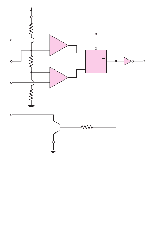
The RS flip-flop is a digital circuit that will be considered in detail in a later
chapter. Here, we will describe only the basic digital function of the flip-flop, so that
the operation of the 555 timer can be explained. When the input
R
is high and input
S
is low, output
¯
Q
is high. The complementary state occurs when
R
is low and
S
is
high, producing a low
¯
Q
output. If both
R
and
S
are low, then output
¯
Q
remains in
its previous state.
Comparator 1 is called the threshold comparator, which compares its input
with an internal voltage reference set at
(
2
3
)V
+
by the voltage divider
R
3
,
R
4
, and
R
5
.
When the input level exceeds this reference level, the threshold comparator output
goes high, producing a high output at flip-flop terminal
¯
Q
. This turns the discharge
transistor on and an external timing capacitor (not shown in this figure) starts to
discharge.
Flip-flop
V
+
(8)
(4)
(3)
R
S
(6)
(5)
(2)
(1)
GND
(7)
R
3
5 kΩ
R
5
5 kΩ
R
8
100 Ω
Discharge
transistor
Comparator 2
Comparator 1
R
4
5 kΩ
Threshold
Reset
Control
voltage
Trigger
Discharge
QA
Buffer
Output
Q
14
(a)
+
–
+
–
C
1
C
2
Figure 15.39 (a) Basic block diagram, 555 IC timer circuit and (b) circuit diagram, LM555
timer circuit
for precision timing, pulse generation, sequential timing, time delay generation,
pulse width modulation, pulse position modulation, and linear ramp generation. The
555 can operate in both astable and monostable modes, with timing pulses ranging
from microseconds to hours. It also has an adjustable duty cycle and can generally
source or sink output currents up to 200 mA.
Basic Operation
The basic block diagram of the 555 IC is shown in Figure 15.39(a). The circuit con-
sists of two comparators, which drive an RS flip-flop, an output buffer, and a transis-
tor that discharges an external timing capacitor. The actual circuit of an LM555 timer
is shown in Figure 15.39(b).
nea80644_ch15_1061-1140.qxd 07/12/2009 3:58 Page 1101 pinnacle MHDQ-New:MHDQ134:MHDQ134-15:
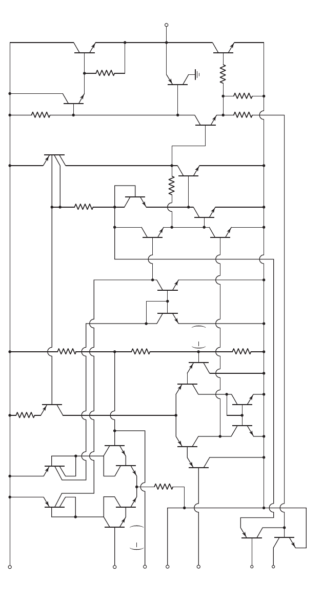
1102 Part 2 Analog Electronics
V
CC
8
Threshold
6
Control
voltage
5
GND
1
Trigger
2
Reset
4
Discharge
7
Q
25
Q
14
Q
12
Q
13
Q
8
Q
7
Q
10
Q
15
Q
16
Q
17
Q
21
Q
27
Q
28
Q
9
R
4
5 kΩ
Q
18
Q
19
Q
20
R
7
4.7 kΩ
R
6
7.5 kΩ
R
11
6.2 kΩ
R
12
3.9 kΩ
R
10
120 Ω
R
9
3.3 kΩ
R
8
100 kΩ
R
5
5 kΩ
3
Outpu
t
R
3
5 kΩ
R
2
1 kΩ
Q
11
Q
5
Q
6
Q
1
Q
2
Q
3
Q
4
R
1
10 kΩ
Q
22
V
CC
1
3
Q
23
Q
24
Q
26
V
CC
2
3
(b)
Figure 15.39 (continued)
nea80644_ch15_1061-1140.qxd 07/12/2009 3:58 Page 1102 pinnacle MHDQ-New:MHDQ134:MHDQ134-15:
Chapter 15 Applications and Design of Integrated Circuits 1103
The internal control voltage node is connected to an external terminal. This pro-
vides external control of the reference level, should the timing period need to be
modified. When not in active use, this terminal should be bypassed to ground with a
0.01
μ
F capacitor, to improve the circuit’s noise immunity.
Comparator 2, called the trigger comparator, compares its input trigger voltage
to an internal voltage reference set to
(
1
3
)V
+
by the same voltage divider as before.
When the output trigger level is reduced below this reference level, the trigger com-
parator output goes high, causing the RS flip-flop to reset. Output
¯
Q
goes low and the
discharge transistor turns off. This comparator triggers on the leading edge of a negative-
going input pulse.
The output stage of the 555 IC is driven by output
¯
Q
of the RS flip-flop. This
output is usually a totem-pole push–pull circuit, or a simple buffer, and is generally
capable of sourcing or sinking 200 mA.
An external reset input to the RS flip-flop overrides all other inputs and is used
to initiate a new timing cycle by turning the discharge transistor on. The reset input
must be less than 0.4 V to initiate a reset. When not actively in use, the reset terminal
should be connected to
V
+
to prevent a false reset.
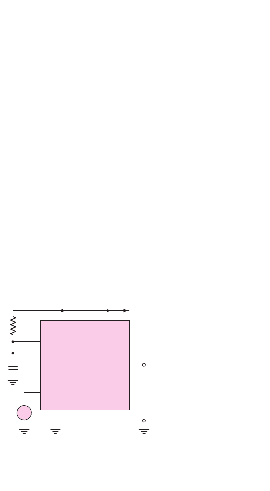
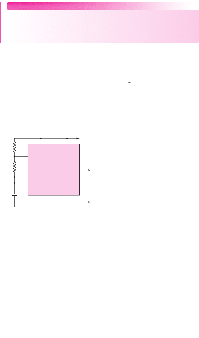
Monostable Multivibrator
A monostable multivibrator, also called a one-shot, operates by charging a timing
capacitor with a current set by an external resistance. When the one-shot is triggered,
the charging network cycles only once during the timing interval. The total timing
interval includes the recovery time needed for the capacitor to charge up to the
threshold level.
The external circuitry and connections for the 555 to be used as a one-shot mul-
tivibrator are shown in Figure 15.40. With a high voltage
V
+
applied to the trigger
input, the trigger comparator output is low, the flip-flop output
¯
Q
is high, the dis-
charge transistor is turned on, and the timing capacitor
C
is discharged to nearly
ground potential. The output of the 555 circuit is then low, which is the quiescent
state of the one-shot.
+V
CC
+V
CC
Reset
Ground
Discharge
Threshold
Trigger
555 Output
v
in
C
+
–
v
C
(t)
+
–
v
O
R
A
+
–
Figure 15.40 The 555 circuit connected as a monostable multivibrator
When a negative-going pulse is applied to the trigger input, the output of the
trigger comparator goes high when the trigger pulse drops below
(
1
3
)V
+
. Output
¯
Q
goes low, which means that the output of the 555 goes high, and the discharge tran-
sistor turns off. The output of the 555 remains high even if the trigger pulse returns
to its initial high value, because the reset input to the flip-flop is still low. The timing
nea80644_ch15_1061-1140.qxd 07/12/2009 3:58 Page 1103 pinnacle MHDQ-New:MHDQ134:MHDQ134-15:

1104 Part 2 Analog Electronics
capacitor charges up exponentially toward a final value of
V
+
through resistor
R
.
The capacitor voltage is given by
v(t) = V
+
(1 − e
−t/RC
)
(15.93)
When
v(t) = (
2
3
)V
+
, the threshold comparator output goes high, resetting the flip-
flop. Output
¯
Q
then goes high and the output of the 555 goes low. The high output at
¯
Q
also turns on the discharge transistor, allowing the timing capacitor to discharge to
near zero volts. The circuit thus returns to its quiescent state.
The width of the output pulse is determined from Equation (15.93). If we set
v(t) = (
2
3
)V
+
and
t = T
, then
2
3
V
+
= V
+
(1 − e
−T/RC
)
(15.94)
Solving for
T
, we have
T = RC ln(3) = 1.1 RC
(15.95)
The width of the output pulse is a function of only the external time constant
RC
; it is independent of the supply voltage
V
+
and any internal circuit parameters.
The triggering input pulse must be of a shorter duration than
T
. The output pulse
height is a function of
V
+
as well as of the internal circuitry. For a bipolar 555, the
output pulse amplitude is approximately 1.7 V below supply voltage
V
+
.
When the output is high and the timing capacitor is charging, another trigger
input pulse will have no effect on the circuit. If desired, the circuit can be reset
during this period by applying a low input to the reset terminal. The output will
return to zero and will remain in this quiescent state until another trigger pulse is
applied.
DESIGN EXAMPLE 15.10
Objective: Design a 555 IC as a monostable multivibrator to produce a specified
output pulse width.
Specifications: The circuit with the configuration shown in Figure 15.40 is to be
designed to produce an output pulse width of 100
μ
s.
Choices: A 555 circuit is available. The final design is to use standard-valued
elements.
Consider the circuit in Figure 15.40. Let
C = 15 nF
.
Solution: Using Equation (15.95), we find that
R =
T
1.1C
=
100 × 10
−6
(1.1)(15 × 10
−9
)
⇒ 6.06 k
Trade-offs: Using standard-valued element values of
C = 12 nF
and
R = 7.5k
will produce an output pulse with a width of 99
μ
s. Element tolerances also need to
be taken into account.
Comment: To a very good approximation, the pulse width is a function of only the
external resistor and capacitance values. A wide range of pulse widths can be ob-
tained by changing these component values.
nea80644_ch15_1061-1140.qxd 07/12/2009 3:58 Page 1104 pinnacle MHDQ-New:MHDQ134:MHDQ134-15:
Chapter 15 Applications and Design of Integrated Circuits 1105
EXERCISE PROBLEM
Ex 15.10: Consider the 555 IC monostable multivibrator. (a) If
R = 20
k
and
C = 0.012 μ
F, what is the resulting output pulse width? (b) Design the circuit to
produce an output signal with a pulse width of
120 μ
s. (Ans. (a)
T = 0.264
ms;
(b) For example, set
C = 0.01 μ
F, then
R = 10.9
k
)
Astable Multivibrator
Figure 15.41 shows a typical external circuit connection for the 555 operating as an
astable multivibrator, also called a timer circuit or clock. The threshold input and
trigger input terminals are connected together. In the astable mode, the timing capac-
itor
C
charges through
R
A
= R
B
until
v(t)
reaches
(
2
3
)V
+
. The threshold compara-
tor output then goes high, forcing the flip-flop output
¯
Q
to go high. The discharge
transistor turns on, and the timing capacitor
C
discharges through
R
B
and the dis-
charge transistor. The capacitor voltage decreases until it reaches
(
1
3
)V
+
, at which
point the trigger comparator switches states and sends
¯
Q
low. The discharge transis-
tor turns off, and the timing capacitor begins to recharge. When
v(t)
reaches the
threshold level of
(
2
3
)V
+
, the cycle repeats itself.
+V
CC
+V
CC
Reset
Ground
Discharge
Threshold
Trigger
555 Output
C
+
–
v
C
+
–
v
O
R
A
R
B
Figure 15.41 Astable multivibrator 555 circuit
When the timing capacitor is charging, during the time
0 < t < T
C
, the capaci-
tor voltage is
v(t) =
1
3
V
+
+
2
3
V
+
(1 − e
−t/τ
A
)
(15.96)
where
τ
A
= (R
A
+ R
B
)C
. At time
t = T
C
, the capacitor voltage reaches the thresh-
old level, or
v(T
C
) =
2
3
V
+
=
1
3
V
+
+
2
3
V
+
(1 − e
−T
C
/τ
A
)
(15.97)
Solving Equation (15.97) for the timing capacitor charging time
T
C
yields
T
C
= τ
A
ln(2) = 0.693(R
A
+ R
B
)C
(15.98)
When the timing capacitor is discharging, during the time
0 < t
< T
D
,the
capacitor voltage is
v(t
) =
2
3
V
+
e
−t
/τ
B
(15.99)
nea80644_ch15_1061-1140.qxd 07/12/2009 3:58 Page 1105 pinnacle MHDQ-New:MHDQ134:MHDQ134-15:

1106 Part 2 Analog Electronics
where
τ
B
= R
B
C
. At time
t
= T
D
, the capacitor voltage reaches the trigger level and
v(T
D
) =
1
3
V
+
=
2
3
V
+
e
−T
D
/τ
B
(15.100)
Solving Equation (15.100) for the timing capacitor discharge time
T
D
yields
T
D
= τ
B
ln(2) = 0.693R
B
C
(15.101)
The period
T
of the astable multivibrator cycle is the sum of the charging period
T
C
and the discharging period
T
D
. The frequency of oscillation is therefore
f =
1
T
=
1
T
C
+ T
D
=
1
0.693(R
A
+2R
B
)C
(15.102)
The duty cycle is defined as the percentage of time the output is high during one
period of oscillation. During the charging time
T
C
, the output is high; during the dis-
charging time, the output is low. The duty cycle is therefore
Duty cycle =
T
C
T
×100% =
R
A
+ R
B
R
A
+2R
B
×100%
(15.103)
Equation (15.103) shows that the duty cycle for this circuit is always greater than
50 percent. The duty cycle approaches 50 percent for
R
A
R
B
and 100 percent for
R
B
R
A
. Alternative circuits can provide duty cycles of less than 50 percent.
DESIGN EXAMPLE 15.11
Objective: Design the 555 IC as an astable multivibrator for a specified frequency
and duty cycle.
Specifications: The circuit with the configuration in Figure 15.41 is to be designed
such that the frequency is 50 kHz and the duty cycle is 75 percent.
Choices: A 555 IC circuit is available. A capacitor with a value of
C = 1nF
is also
available.
Solution: The frequency of oscillation, as given by Equation (15.102), is
f =
1
0.693(R
A
+2R
B
)C
Therefore,
R
A
+2R
B
=
1
(0.693) fC
=
1
(0.693)(50 × 10
3
)(1 × 10
−9
)
⇒ 28.9k
(15.104)
The duty cycle, given by Equation (15.103), is
Duty cycle = 0.75 =
R
A
+ R
B
R
A
+2R
B
which yields
R
A
= 2R
B
(15.105)
Combining Equations (15.104) and (15.105), we find that
R
A
= 14.5k and R
B
= 7.23 k
nea80644_ch15_1061-1140.qxd 07/12/2009 3:58 Page 1106 pinnacle MHDQ-New:MHDQ134:MHDQ134-15:

Chapter 15 Applications and Design of Integrated Circuits 1107
Trade-offs: If standard-valued resistors are required, then
R
A
= 13 k
and
R
B
=
7.5k
would provide a frequency of 51.5 kHz and a duty cycle of 73.2 percent.
Comment: A wide range of oscillation frequencies can be obtained by changing the
resistance and capacitance values.
EXERCISE PROBLEM
Ex 15.11: The 555 IC is connected as an astable multivibrator. Let
R
A
= 20 k
,
R
B
= 80 k
, and
C = 0.01 μF
. Determine the frequency of oscillation and the
duty cycle. (Ans.
f = 802 Hz
, duty cycle
= 55.6%
)
Other Applications
When the 555 is connected in the monostable mode, an external signal applied to the
control voltage terminal will change the charging time of the timing capacitor and the
pulse width. If the one-shot is triggered with a continuous pulse train, the output
pulse width will be modulated by the external signal. This circuit is known as a pulse
width modulator (PWM).
A pulse position modulator can also be developed using the astable mode.
A modulating signal applied to the control voltage terminal will vary the pulse position,
which will be controlled by the modulating signal in a manner similar to the PWM.
Finally, a linear ramp generator can be constructed, again using the 555 mono-
stable mode. The normal charging pattern of the timing capacitor is exponential
because of the
RC
circuit. If resistor
R
is replaced by a constant current source, a
linear ramp will be generated.
Test Your Understanding
TYU 15.10 (a) The Schmitt trigger oscillator is shown in Figure 15.35. The saturated
output voltages are
±5
V, and
R
1
= R
2
= 15
k
,
R
X
= 20
k
, and
C
X
= 0.05 μ
F.
Determine the frequency of oscillation and the duty cycle. (b) Changing only the
value of
R
X
from part (a), determine the value of
R
X
such that the frequency of os-
cillation is
f = 1.2
kHz. (Ans. (a)
f = 454.5
Hz, 50% duty cycle; (b)
R
X
= 7.576
k
)
TYU 15.11 Consider the monostable multivibrator in Figure 15.37 with parameters:
V
P
= 8V
,
V
γ
= 0.7
V,
C
X
= 0.01 μF
,
R
X
= 10 k
,
R
1
= 20 k
, and
R
2
= 40 k
.
Determine the output pulse width and recovery time. (Ans.
T = 48.9 μs
,
t
2
= 37.8 μs
)
TYU 15.12 Design the 555 IC as an astable multivibrator to deliver a 1 kHz signal
with a 55 percent duty cycle. (Ans. For example,
C = 0.01 μF
,
R
A
= 14.43 k
,
R
B
= 64.9k
)
15.5 INTEGRATED CIRCUIT POWER AMPLIFIERS
Objective: • Analyze and design IC power amplifiers that usually con-
sist of high-gain small-signal amplifiers in cascade with an output stage.
Most IC power amplifiers consist of a high-gain small-signal amplifier cascaded with
a class-AB output stage. Some IC power amplifiers are a fixed-gain circuit with
nea80644_ch15_1061-1140.qxd 07/12/2009 3:58 Page 1107 pinnacle MHDQ-New:MHDQ134:MHDQ134-15: