Neamen D. Microelectronics: Circuit Analysis and Design
Подождите немного. Документ загружается.

1088 Part 2 Analog Electronics
Voltage
v
+
does not remain constant; rather, it is a function of the output voltage.
Input signal
v
I
is applied to the inverting terminal.
Voltage Transfer Characteristics
To determine the voltage transfer characteristics, we assume that the output of the
comparator is in one state, namely
v
O
= V
H
, which is the high state. Then
v
+
=
R
1
R
1
+ R
2
V
H
(15.67)
As long as the input signal is less than
v
+
, the output remains in its high state. The
crossover voltage occurs when
v
I
= v
+
and is defined as
V
TH
. We have
V
TH
=
R
1
R
1
+ R
2
V
H
(15.68)
When
v
I
is greater than
V
TH
, the voltage at the inverting terminal is greater than that
at the noninverting terminal. The differential input voltage
(v
I
− V
TH
)
is amplified
by the open-loop gain of the comparator, and the output switches to its low state, or
v
O
= V
L
. Voltage
v
+
then becomes
v
+
=
R
1
R
1
+ R
2
V
L
(15.69)
Since
V
L
< V
H
, the input voltage
v
I
is still greater than
v
+
, and the output re-
mains in its low state as
v
I
continues to increase. This voltage transfer characteristic
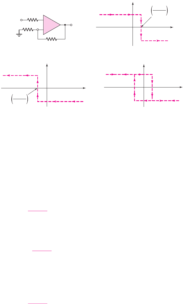
is shown in Figure 15.28(b). Implicit in these transfer characteristics is the assump-
tion that
V
H
is positive and
V
L
is negative.
v
I
v
O
R
1
R
2
v
+
R
1
⎜⎜ R
2
v
O
v
I
V
TH
= V
H
R
1
R
1
+ R
2
V
TL
= V
L
R
1
R
1
+ R
2
v
O
v
I
v
O
v
I
V
TL
V
TH
(a) (b)
(c) (d)
–
+
Figure 15.28 (a) Schmitt trigger circuit, (b) voltage transfer characteristic as input voltage
increases, (c) voltage transfer characteristic as input voltage decreases, and (d) net voltage
transfer characteristics, showing hysteresis effect
nea80644_ch15_1061-1140.qxd 07/12/2009 3:58 Page 1088 pinnacle MHDQ-New:MHDQ134:MHDQ134-15:

Chapter 15 Applications and Design of Integrated Circuits 1089
Now consider the transfer characteristic as
v
I
decreases. As long as
v
I
is larger
than
v
+
= [R
1
/(R
1
+ R
2
)]V
L
, the output remains in its low saturation state. The
crossover voltage now occurs when
v
I
= v
+
and is defined as
V
TL
. We have
V
TL
=
R
1
R
1
+ R
2
V
L
(15.70)
As
v
I
drops below this value, the voltage at the noninverting terminal is greater than
that at the inverting terminal. The differential voltage at the comparator terminals is
amplified by the open-loop gain, and the output switches to its high state, or
v
O
= V
H
. As
v
I
continues to decrease, it remains less than
v
+
; therefore,
v
O
remains
in its high state. This voltage transfer characteristic is shown in Figure 15.28(c).
Complete Voltage Transfer and Bistable Characteristics
The complete voltage transfer characteristics of the Schmitt trigger in Figure 15.28(a)
combine the characteristics in Figures 15.28(b) and 15.28(c). These complete char-
acteristics are shown in Figure 15.28(d). As shown, the crossover voltages depend on
whether the input voltage is increasing or decreasing. The complete transfer charac-
teristics therefore show a hysteresis effect. The width of the hysteresis is the differ-
ence between the two crossover voltages
V
TH
and
V
TL
.
The bistable characteristic of the circuit occurs around the point
v
I
= 0
,at
which the output may be in either its high or low state. The output remains in either
state as long as
v
I
remains in the range
V
TL
<v
I
< V
TH
. The output switches states
only if the input increases above
V
TH
or decreases below
V
TL
.
EXAMPLE 15.6
Objective: Determine the hysteresis width of a particular Schmitt trigger.
Consider the Schmitt trigger in Figure 15.28(a), with parameters
R
1
= 10 k
and
R
2
= 90 k
. Let
V
H
= 10 V
and
V
L
=−10
V.
Solution: From Equation (15.68), the upper crossover voltage is
V
TH
=
R
1
R
1
+ R
2
V
H
=
10
10 + 90
(10) = 1V
and from Equation (15.70), the lower crossover voltage is
V
TL
=
R
1
R
1
+ R
2
V
L
=
10
10 + 90
(−10) =−1V
The hysteresis width is therefore
(V
TH
− V
TL
) = 2
V.
Comment: The hysteresis width can be designed to be larger or smaller for specific
applications by adjusting the voltage divider ratio of
R
1
and
R
2
.
EXERCISE PROBLEM
Ex 15.6: Consider the comparator circuit in Figure 15.28(a). Assume high and
low saturated output voltages of
+
9 V and
−
9 V, respectively. Design the circuit
such that the crossover voltages are
±0.5
V. The minimum resistance is to be
10 k
. (Ans. Set
R
1
= 10
k
, then
R
2
= 170
k
)
nea80644_ch15_1061-1140.qxd 07/12/2009 3:58 Page 1089 pinnacle MHDQ-New:MHDQ134:MHDQ134-15:
1090 Part 2 Analog Electronics
The complete voltage transfer characteristics in Figure 15.28(d) show the in-
verting characteristics of this particular Schmitt trigger. When the input signal be-
comes sufficiently positive, the output is in its low state; when the input signal is
sufficiently negative, the output is in its high state. Since the input signal is applied to
the inverting terminal of the comparator, this characteristic is as expected.
Additional Schmitt Trigger Configurations
A noninverting Schmitt trigger can be designed by applying the input signal to the
network connected to the comparator noninverting terminal. Also, both crossover
voltages of a Schmitt trigger circuit can be shifted in either a positive or negative di-
rection by applying a reference voltage. We will study these general circuit configu-
rations, the resulting voltage transfer characteristics, and an application of a Schmitt
trigger circuit in this section.
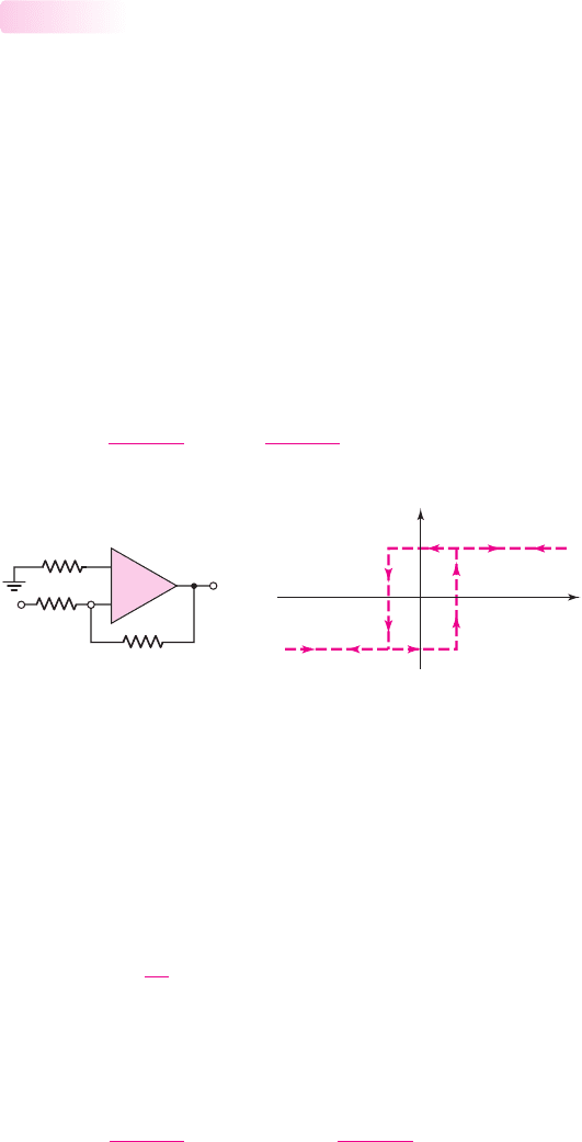
Noninverting Schmitt Trigger Circuit
Consider the circuit in Figure 15.29(a). The inverting terminal is held essentially at
ground potential, and the input signal is applied to resistor
R
1
, which is connected to
the comparator noninverting terminal. Voltage
v
+
at the noninverting terminal then
becomes a function of both the input signal
v
I
and the output voltage
v
O
. Using
superposition, we find that
v
+
=
R
2
R
1
+ R
2
v
I
+
R
1
R
1
+ R
2
v
O
(15.71)
15.3.3
R
1
⎜⎜ R
2
R
1
R
2
v
+
v
O
v
I
v
O
v
I
V
TL
V
TH
(a) (b)
–
+
Figure 15.29 (a) Noninverting Schmitt trigger circuit and (b) voltage transfer characteristics
If
v
I
is negative, and the output is in its low state, then
v
O
= V
L
(assumed to be neg-
ative),
v
+
is negative, and the output remains in its low saturation state. Crossover
voltage
v
I
= V
TH
occurs when
v
+
= 0
and
v
O
= V
L
, or, from Equation (15.71),
0 = R
2
V
TH
+ R
1
V
L
(15.72(a))
which can be written
V
TH
=−
R
1
R
2
V
L
(15.72(b))
Since
V
L
is negative,
V
TH
is positive.
If we let
v
I
= V
TH
+δ
, where
δ
is a small positive voltage, the input voltage is
just greater than the crossover voltage and Equation (15.71) becomes
v
+
=
R
2
R
1
+ R
2
(V
TH
+δ) +
R
1
R
1
+ R
2
V
L
(15.73)
nea80644_ch15_1061-1140.qxd 07/12/2009 3:58 Page 1090 pinnacle MHDQ-New:MHDQ134:MHDQ134-15:
Chapter 15 Applications and Design of Integrated Circuits 1091
Equation (15.73) then becomes
v
+
=
R
2
R
1
+ R
2
−R
1
R
2
V
L
+
R
2
R
1
+ R
2
δ +
R
1
R
1
+ R
2
V
L
(15.74(a))
or
v
+
=
R
2
R
1
+ R
2
δ>0
(15.74(b))
When
v
+
> 0
, the output switches to its high saturation state.
The lower crossover voltage
v
I
= V
TL
occurs when
v
+
= 0
and
v
O
= V
H
. From
Equation (15.71), we have
0 = R
2
V
TL
+ R
1
V
H
(15.75(a))
which can be written
V
TL
=−
R
1
R
2
V
H
(15.75(b))
Since
V
H
> 0
, then
V
TL
< 0
.
The complete voltage transfer characteristics are shown in Figure 15.29(b). We
again note the hysteresis effect and the bistable characteristic around
v
I
= 0
. With
v
I
sufficiently positive, the output is in its high state; with
v
I
sufficiently negative,
the output is in its low state. The circuit thus exhibits the noninverting transfer
characteristic.
Schmitt Trigger Circuits with Applied Reference Voltages
The switching voltage of a Schmitt trigger is defined as the average value of
V
TH
and
V
TL
. For the two circuits in Figure 15.28(a) and 15.29(a), the switching voltages
are zero, assuming
V
TL
=−V
TH
. In some applications, the switching voltage must
be either positive or negative. Both crossover voltages can be shifted in either a
positive or negative direction by applying a reference voltage.
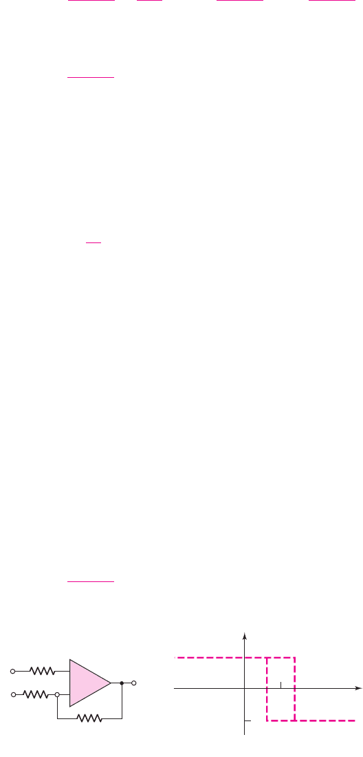
Figure 15.30(a) shows an inverting Schmitt trigger with a reference voltage
V
REF
. The complete voltage transfer characteristics are shown in Figure 15.30(b).
The switching voltage
V
S
, assuming
V
H
and
V
L
are symmetrical about zero, is
given by
V
S
=
R
2
R
1
+ R
2
V
REF
(15.76)
R
1
⎜⎜ R
2
R
1
R
2
v
+
v
O
v
I
V
REF
v
O
v
I
V
TL
V
H
V
TH
V
S
V
L
(a) (b)
–
+
Figure 15.30 (a) Inverting Schmitt trigger circuit with applied reference voltage and
(b) voltage transfer characteristics
nea80644_ch15_1061-1140.qxd 07/12/2009 3:58 Page 1091 pinnacle MHDQ-New:MHDQ134:MHDQ134-15:

1092 Part 2 Analog Electronics
Note that the switching voltage is not the same as the reference voltage. The upper
and lower crossover voltages are
V
TH
= V
S
+
R
1
R
1
+ R
2
V
H
(15.77(a))
and
V
TL
= V
S
+
R
1
R
1
+ R
2
V
L
(15.77(b))
A noninverting Schmitt trigger with a reference voltage is shown in Fig-
ure 15.31(a), and the complete voltage transfer characteristics are shown in Figure
15.31(b). The switching voltage
V
S
, again assuming
V
H
and
V
L
are symmetrical
about zero, is given by
V
S
=
1 +
R
1
R
2
V
REF
(15.78)
v
O
v
I
V
H
V
L
V
TL
V
TH
V
S
(a) (b)
+
–
R
1
⎜⎜R
2
R
1
R
2
v
+
v
O
v
I
V
REF
–
+
Figure 15.31 (a) Noninverting Schmitt trigger circuit with applied reference voltage and
(b) voltage transfer characteristics
and the upper and lower crossover voltages are
V
TH
= V
S
−
R
1
R
2
V
L
(15.79(a))
and
V
TL
= V
S
−
R
1
R
2
V
H
(15.79(b))
If the output saturation voltages are symmetrical such that
V
L
=−V
H
, then the
crossover voltages are symmetrical about the switching voltage
V
S
.
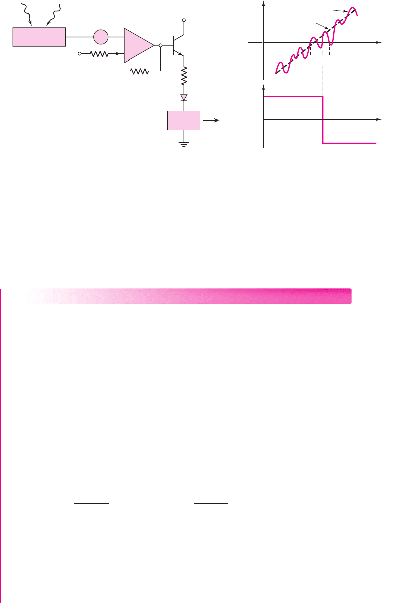
Schmitt Trigger Application
Let us reconsider the street light control in Figure 15.27(a), which included a noise
source. Figure 15.32(a) shows the same basic circuit, except that a Schmitt trigger is
used instead of a simple comparator.
The input signal
v
I
is again assumed to increase linearly with time. The total
input signal
v
I
is
v
I
with the noise signal superimposed, as shown in Figure 15.32(b).
At time
t
1
, the input signal becomes greater than the switching voltage
V
S
. The out-
put, however, does not switch, since
v
I
< V
TH
. This means that the input signal is
less than the upper crossover voltage. At time
t
2
, the input signal becomes larger than
the crossover voltage, or
v
I
> V
TH
, and the output signal switches from its high to
its low state. At time
t
3
, the input signal drops below
V
S
, but the output does not
switch states since
v
I
> V
TL
. This means that the input signal remains greater than
nea80644_ch15_1061-1140.qxd 07/12/2009 3:58 Page 1092 pinnacle MHDQ-New:MHDQ134:MHDQ134-15:
Chapter 15 Applications and Design of Integrated Circuits 1093
t
v
O
(a)
(b)
(c)
Light Variable
light
v
I
v
n
v
O
V
CC
R
D
1
R
1
R
2
+–
–
+
Relay
switch
Photodetector
circuit
t
V
S
V
REF
V
TH
V
TL
v
I
′
v
I
t
1
t
2
t
3
Figure 15.32 (a) Application of Schmitt trigger circuit including input noise source,
(b) input signal, and (c) output signal, showing elimination of chatter effect
the lower crossover voltage. The Schmitt trigger circuit thus eliminates the chatter
effect that occurs in the output voltage in Figure 15.27(c). Elimination of the chatter
in the output voltage response results directly from the hysteresis effect in the
Schmitt trigger characteristics.
DESIGN EXAMPLE 15.7
Objective: Design a Schmitt trigger circuit for the photodetector switch circuit.
Specifications: The Schmitt trigger circuit with the configuration shown in Figure
15.32(a) is to be designed such that the switching voltage is
V
S
= 2
V and the hys-
teresis width is 60 mV. Assume
V
H
= 5
V and
V
L
=−5
V.
Choices: An ideal comparator is available and standard-valued resistors are to be
used in the final design.
Solution: The Schmitt trigger circuit is the inverting type, for which the voltage
transfer characteristics are shown in Figure 15.30(b). From Equations (15.77(a)) and
(15.77(b)), the hysteresis width is
V
TH
− V
TL
=
R
1
R
1
+ R
2
(V
H
− V
L
)
so
0.060 =
R
1
R
1
+ R
2
[5 − (−5)] = 10
R
1
R
1
+ R
2
which yields
R
2
/R
1
= 165.7
. We can find the reference voltage from Equation
(15.76), which can be rewritten to obtain
V
REF
=
1 +
R
1
R
2
V
S
=
1 +
1
165.7
(2) = 2.012 V
Resistor values of
R
1
= 100
and
R
2
= 16.57
k
will satisfy the requirements. The
crossover voltages are thus
V
TH
= 2.03
V and
V
TL
= 1.97
V.
nea80644_ch15_1061-1140.qxd 07/12/2009 3:58 Page 1093 pinnacle MHDQ-New:MHDQ134:MHDQ134-15:

1094 Part 2 Analog Electronics
Trade-offs: If we use standard-valued resistors
R
1
= 120
and
R
2
= 20 k
,the
hysteresis width is
V
TH
− V
TL
=
R
1
R
1
+ R
2
(V
H
− V
L
)
=
0.12
0.12 + 20
[5 − (−5)] → 59.6mV
If we are able to use a reference voltage of 2.012 V, then the switching voltage is
V
S
=
R
2
R
1
+ R
2
V
REF
=
20
0.12 + 20
(2.012) = 2.0V
Resistor tolerances will also affect the results, but will not be considered here.
Comment: In this case, the output chatter effect is eliminated for noise signals with
amplitudes lower than 30 mV. The hysteresis width can be adjusted up or down to fit
specific application requirements in which the noise signal is larger or smaller than
that given in this example.
EXERCISE PROBLEM
Ex 15.7: Redesign the street light control circuit shown in Figure 15.32(a) such
that the switching voltage is
V
S
= 1V
and the hysteresis width is 100 mV. As-
sume
V
H
=+10 V
and
V
L
=−10 V
. Also, find R such that
I = 200 μA
when
v
O
= V
H
. Assume
V
BE
(on) = 0.7V
and
V
γ
= 0.7V
, and assume the relay
switch resistance is 100
. (Ans.
R
2
/R
1
= 199
,
V
REF
= 1.005 V
,
R = 42.9k
)
Schmitt Triggers with Limiters
In the Schmitt trigger circuits we have thus far considered, the open-loop saturation
voltages of the comparator may not be very precise and may also vary from one
comparator to another. The output saturation voltages can be controlled and made
more precise by adding limiter networks.
A direct approach at limiting the output is shown in Figure 15.33. Two back-to-
back Zener diodes are connected between the output and ground. Assuming the two
diodes are matched, the output is limited to either the positive or negative value of
(V
γ
+ V
Z
)
, where
V
γ
is the forward diode voltage and
V
Z
is the reverse Zener volt-
age. Resistor R is chosen to produce a specified current in the diodes.
15.3.4
v
O
v
I
V
TL
V
TH
(V
g
+ V
Z
)
– (V
g
+ V
Z
)
(a) (b)
v
I
v
O
D
Z1
D
Z2
R
1
R
2
R
–
+
Figure 15.33 (a) Schmitt trigger with Zener diode limiters and (b) voltage transfer
characteristics
nea80644_ch15_1061-1140.qxd 07/12/2009 3:58 Page 1094 pinnacle MHDQ-New:MHDQ134:MHDQ134-15:
Chapter 15 Applications and Design of Integrated Circuits 1095
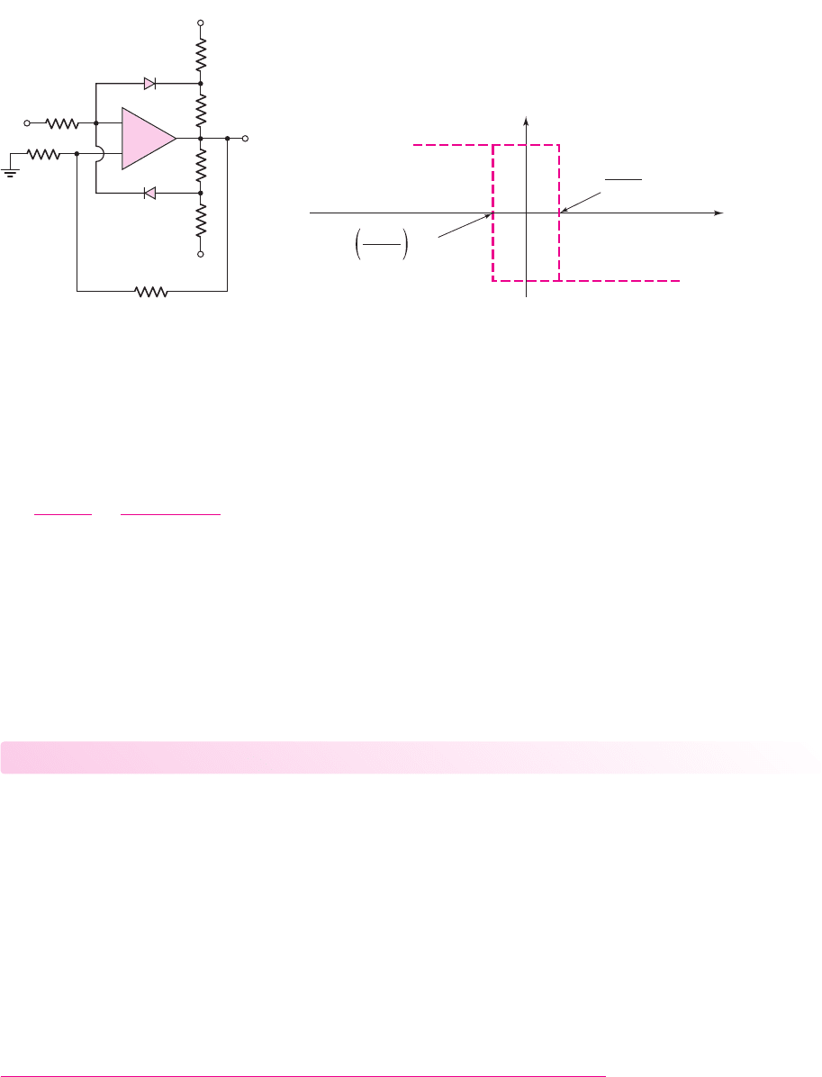
Another Schmitt trigger with a limiter is shown in Figure 15.34(a). If we assume that
v
I
= 0
and
v
O
is in its high state, then
D
2
is on and
D
1
is off. Neglecting currents in the
100 k
resistor, we have
v
2
=+V
γ
, where
V
γ
is the forward diode voltage. We can write
v
O
−v
2
1
=
v
2
−(−V
REF
)
1
(15.80)
Solving for
v
O
yields
v
O
= V
REF
+2V
γ
(15.81)
which means that the output voltage can be controlled and can be designed more
accurately. The ideal hysteresis characteristics for this Schmitt trigger are shown in
Figure 15.34(b). As
v
I
increases or decreases, a small current flows in the 100 k
resistor, producing a nonzero slope in the voltage transfer characteristics. The slope
is on the order of 1/100, which is quite small.
Test Your Understanding
TYU 15.7 A noninverting Schmitt trigger is shown in Figure 15.29(a) Its saturated out-
put voltages are
±12
V. Design the circuit to obtain
±200
mV crossover voltages. The
maximum resistance value is to be 200 k
. (Ans. Set
R
2
= 200
k
, then
R
1
= 3.33
k
)
TYU 15.8 For the Schmitt trigger in Figure 15.30(a), the parameters are:
V
REF
= 2V
,
V
H
= 10 V
,
V
L
=−10 V
,
R
1
= 1k
, and
R
2
= 10 k
: (a) Determine
V
S
,
V
TH
, and
V
TL
. (b) Let
v
I
be a triangular wave with a zero average voltage, a 10 V peak ampli-
tude, and a 10 ms period. Sketch
v
O
versus time over two periods. Label the appro-
priate voltages and times. (Ans. (a)
V
S
= 1.82 V
,
V
TH
= 2.73 V
,
V
TL
= 0.91 V
)
TYU 15.9 Consider the Schmitt trigger in Figure 15.31(a). Let
V
H
= 9
V and
V
L
=−9
V. Design the circuit such that
V
S
=−2
V and the hysteresis width is 0.5 V.
The minimum resistance is to be 10 k
. (Ans. Set
R
1
= 10
k
, then
R
2
= 360
k
,
V
REF
=−1.946
V)
v
O
v
O
v
I
(V
REF
+ 2V
g
)
V
TH
=
(V
REF
+ 2V
g
)
R
1
R
2
+ R
1
– (V
REF
+ 2V
g
)
(V
REF
+ 2V
g
)
V
TL
= –
R
1
R
2
+ R
1
(a) (b)
–V
REF
V
REF
1 kΩ
100 kΩ
v
1
D
1
D
2
R
2
R
1
v
2
v
I
1 kΩ
1 kΩ
1 kΩ
V
REF
–
+
Figure 15.34 (a) Inverting Schmitt trigger with diode limiters and (b) voltage transfer
characteristics
nea80644_ch15_1061-1140.qxd 07/12/2009 3:58 Page 1095 pinnacle MHDQ-New:MHDQ134:MHDQ134-15:

1096 Part 2 Analog Electronics
15.4 NONSINUSOIDAL OSCILLATORS
AND TIMING CIRCUITS
Objective: • Analyze and design multivibrator circuits that provide
signals with particular waveforms.
Many applications, especially digital electronic systems, use a nonsinusoidal square-
wave oscillator to provide a clock signal for the system. This type of oscillator is
called an astable multivibrator. In other applications, a single pulse of known height
and width is used to initiate a particular set of functions. This type of oscillator is
called a monostable multivibrator. First, we will examine the Schmitt trigger con-
nected as an oscillator. Then we will analyze the 555 timer circuit. Although used ex-
tensively in digital electronic systems, these circuits are included here as comparator
circuit applications.
Schmitt Trigger Oscillator
The Schmitt trigger can be used in an oscillator circuit to generate a square-wave out-
put signal. This is accomplished by adding an RC network to the negative feedback
loop of the Schmitt trigger as shown in Figure 15.35. As we will see, this circuit has
no stable states. It is therefore called an astable multivibrator.
Initially, we set
R
1
and
R
2
equal to the same value, or
R
1
= R
2
≡ R
. We assume
that the output switches symmetrically about zero volts, with the high saturated out-
put denoted by
V
H
= V
P
and the low saturated output denoted by
V
L
=−V
P
. If
v
O
is low, or
v
O
=−V
P
, then
v
+
=−(
1
2
)V
P
. When
v
X
drops just slightly below
v
+
,the
output switches high so that
v
O
=+V
P
and
v
+
=+(
1
2
)V
P
. The
R
X
C
X
network sees
a positive step-increase in voltage, so capacitor
C
X
begins to charge and voltage
v
X
starts to increase toward a final value of
V
P
.
The general equation for the voltage across a capacitor in an
RC
network is
v
X
= v
Final
+
(
v
Initial
−v
Final
)
e
−t/τ
(15.82)
where
v
Initial
is the initial capacitor voltage at
t = 0
,
v
Final
is the final capacitor volt-
age at
t =∞
, and
τ
is the time constant. We can now write
v
X
= V
P
+
−
V
P
2
− V
P
e
−t/τ
x
(15.83(a))
or
v
X
= V
P
−
3V
P
2
e
−t/τ
x
(15.83(b))
where
τ
x
= R
X
C
X
. Voltage
v
X
increases exponentially with time toward a final
voltage
V
P
. However, when
v
X
becomes just slightly greater than
v
+
=+(
1
2
)V
P
,
the output switches to its low state of
v
O
=−V
P
and
v
+
=−(
1
2
)V
P
. The
R
X
C
X
network sees a negative step change in voltage, so capacitor
C
X
now begins to
discharge and voltage
v
X
starts to decrease toward a final value of
−V
P
. We can
now write
v
X
=−V
P
+
+
V
P
2
−(−V
P
)
e
−(t−t
1
)/τ
x
(15.84(a))
15.4.1
v
X
C
X
R
X
R
2
R
1
v
O
–
+
Figure 15.35 Schmitt trigger
oscillator
nea80644_ch15_1061-1140.qxd 07/12/2009 3:58 Page 1096 pinnacle MHDQ-New:MHDQ134:MHDQ134-15:

Chapter 15 Applications and Design of Integrated Circuits 1097
or
v
X
=−V
P
+
3V
P
2
e
−(t−t
1
)/τ
x
(15.84(b))
where
t
1
is the time at which the output switches to its low state. The capacitor voltage
then decreases exponentially with time. When
v
X
decreases to
v
+
=−(
1
2
)V
P
, the out-
put again switches to its high state. The process continues to repeat itself, which means
that this positive-feedback circuit oscillates producing a square-wave output signal.
Figure 15.36 shows the output voltage
v
O
and the capacitor voltage
v
X
versus time.
t
+V
P
Toward
V
P
Toward
–V
P
v
O
v
O
v
O
v
X
v
X
v
X
t
1
t
2
t
3
–V
P
V
P
2
–
V
P
2
Figure 15.36 Output voltage and capacitor voltage versus time for Schmitt trigger oscillator
Time
t
1
can be found from Equation (15.83(b)) by setting
t = t
1
when
v
X
= V
P
/2
,or
V
P
2
= V
P
−
3V
P
2
e
−t
1
/τ
x
(15.85)
Solving for
t
1
, we find that
t
1
= τ
x
ln 3 = 1.1R
X
C
X
(15.86)
From a similar analysis using Equation (15.84(b)), we find that the difference
between
t
2
and
t
1
is also 1.l
R
X
C
X
; therefore, the period of oscillation
T
is
T = 2.2R
X
C
X
(15.87)
and the frequency of oscillation is
f =
1
T
=
1
2.2R
X
C
X
(15.88)
As an example of an application of this circuit, a variable frequency oscillator is
created by letting
R
X
be a variable resistor.
The duty cycle of the oscillator is defined as the percentage of time that the out-
put voltage
v
O
is in its high state. For the circuit just considered, the duty cycle is
50 percent, as seen in Figure 15.36. This is a result of the symmetrical output volt-
ages
+V
P
and
−V
P
. If asymmetrical output voltages are used, then the duty cycle
changes from the 50 percent value.
DESIGN EXAMPLE 15.8
Objective: Design a Schmitt trigger oscillator for a specified frequency.
Specifications: Assume that an ideal comparator is available. Use standard-valued
resistors and capacitors in the final design.
nea80644_ch15_1061-1140.qxd 07/12/2009 3:58 Page 1097 pinnacle MHDQ-New:MHDQ134:MHDQ134-15: