Neamen D. Microelectronics: Circuit Analysis and Design
Подождите немного. Документ загружается.


+
–
V
Z
D
V
O
10 kΩ
10 kΩ
R
o
= 0.5 kΩ
R
1
=
4 kΩ
V
+
R
L
I
O
–
+
Figure 15.50 Figure for Exercise Ex15.15
1118
Part 2 Analog Electronics
Equation (15.123) relates the fractional change in output voltage to a fractional
change in output current. Although valid for only small variations in voltage and cur-
rent, this equation provides insight into the concept of load regulation.
EXAMPLE 15.15
Objective: Determine the output resistance and the variation in output voltage of a
series-pass regulator.
Assume an open-loop gain of
A
OL
= 1000
, a reference voltage of
V
REF
= 5V
,a
nominal output voltage of
V
O
= 10 V
, and a nominal output current of
I
O
= 100 mA
.
Solution: From Equation (15.122), the output resistance is
R
of
=
2V
T
I
O
V
O
V
REF
1
A
OL
=
2(0.026)(10)
(0.10)(5)(1000)
⇒1.04 m
From Equation (15.123), the relative change in output voltage is
V
O
V
O
=−
I
O
I
O
2V
T
V
REF
1
A
OL
=−
I
O
I
O
2(0.026)
(5)(1000)
or
V
O
V
O
=−
I
O
I
O
(1.04 × 10
−5
)
A 10 percent change in output current results in only a
1.04 × 10
−4
percent change
in output voltage.
Comment: An output resistance in the m
range is typical of voltage regulators, and
a change of only
10
−4
percent in output for a 10 percent change in current is a good
load regulation value.
EXERCISE PROBLEM
*Ex 15.15: Consider the voltage regulator in Figure 15.50. The Zener diode is
ideal, with
V
Z
= 6.3V
, and the op-amp has a finite open-loop gain of
A
OL
= 1000
. The no-load current is
I
O
= 1mA
, and the full-load current is
I
O
= 100 mA
. Determine the load regulation. (Ans. 0.786%)
nea80644_ch15_1061-1140.qxd 07/12/2009 3:59 Page 1118 pinnacle MHDQ-New:MHDQ134:MHDQ134-15:
Chapter 15 Applications and Design of Integrated Circuits 1119
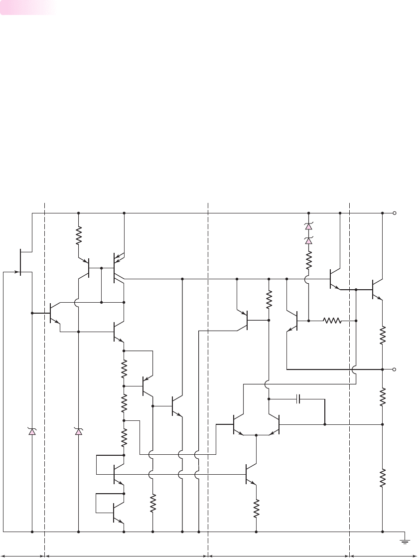
Positive Voltage Regulator
In this section, we will analyze an example of a three-terminal positive voltage regu-
lator fabricated as an IC. The equivalent circuit, shown in Figure 15.51, is part of the
LM78LXX series, in which the XX designation indicates the output voltage of
the regulator. For example, an LM78L08 is an 8 V regulator.
Basic Circuit Description
Once the bias current is established, Zener diode
D
2
provides the basic reference
voltage. Transistors
Q
15
and
Q
16
and diode
D
1
form a start-up circuit that applies
the initial bias to the reference voltage circuit. As the voltage across
D
2
reaches the
Zener voltage, transistor
Q
15
turns off, since the B–E voltage goes to zero (
D
1
and
D
2
are identical) and, the start-up circuit is then effectively disconnected from the
reference voltage circuit.
15.6.4
V
+
Startup
Current amp.Error amp..Reference voltage
R
6
=
2.84 kΩ
R
5
=
7.8 kΩ
R
1
=
3.9 kΩ
R
2
=
3.4 kΩ
R
3
=
576 Ω
Q
3
Q
2
Q
1
Q
6
Q
7
Q
8
Q
12
Q
10
D
3
D
4
Ground
Q
11
Q
9
C
1
= 5 pF
Q
13
Q
5
Q
4
Q
16
Q
15
D
2
D
1
R
13
=
2.23 kΩ
R
11
=
1.9 Ω
R
15
=
100 Ω
R
14
=
5 kΩ
R
4
R
9
=
5.8 kΩ
R
12
V
O
Q
14
Figure 15.51 Equivalent circuit, LM78LXX series three-terminal positive voltage regulator
nea80644_ch15_1061-1140.qxd 07/12/2009 3:59 Page 1119 pinnacle MHDQ-New:MHDQ134:MHDQ134-15:

1120 Part 2 Analog Electronics
The reference portion of the circuit is composed of Zener diode
D
2
and transis-
tors
Q
3
,
Q
2
, and
Q
1
, which are used for temperature compensation. The temperature
compensation aspects of the circuit are discussed later in this section. Zener diode
D
2
is biased by the current-source transistor
Q
4
. The temperature-compensated portion
of the reference voltage at the node between
R
1
and
R
2
is applied to the base of
Q
7
,
which is part of the error amplifier.
The bias current in
Q
4
is established by the current in
Q
5
, which is a multiple-
collector, multiple-emitter transistor. Transistor
Q
5
is biased by the current in
Q
3
,
which is controlled by the Zener voltage across
D
2
and the B–E junction voltages of
Q
3
, Q
2
, and
Q
1
. Consequently, the bias currents in the reference portion of the
circuit become almost independent of the input supply voltage. This in turn means
that the reference voltage, and thus the output voltage are essentially independent of
the power supply voltage. The overall result is very good line regulation.
The error amplifier is the differential pair
Q
7
and
Q
8
, biased by
Q
6
and
R
6
. The
error amplifier output is the input to the base of
Q
9
, which is connected as an emitter
follower and forms part of the drive for the series-pass transistors. The series-pass
output transistors
Q
10
and
Q
11
are connected in a Darlington emitter-follower
configuration.
A fraction of the output voltage, determined by the voltage divider
R
12
and
R
13
,
is fed back to the base of
Q
8
, which is the error-amplifier inverting terminal. If the
output voltage is slightly below its nominal value, then the base voltage at
Q
8
is
smaller than that at
Q
7
, and the current in
Q
7
becomes a larger fraction of the total
diff-amp bias current. The increased current in
Q
7
induces a larger current in
Q
10
,
which in turn produces a larger current in
Q
11
and increases the output voltage to the
proper value. The opposite process occurs if the output voltage is above its nominal
value.
EXAMPLE 15.16
Objective: Determine the bias current, temperature-compensated reference voltage,
and required resistor
R
12
in a particular LM78LXX voltage regulator.
Consider the voltage regulator circuit in Figure 15.51. Assume Zener diode volt-
ages of
V
Z
= 6.3V
and transistor parameters of
V
BE
(npn) = V
EB
(pnp) = 0.6V.
Design
R
12
such that
V
O
= 8V
.
Solution: The bias current, neglecting base currents, is found as
I
C3
= I
C5
=
V
Z
−3V
BE
(npn)
R
3
+ R
2
+ R
1
=
6.3 − 3(0.6)
0.576 + 3.4 +3.9
= 0.571 mA
The temperature-compensated portion of the reference voltage, which is the input to
the base of
Q
7
,is
V
B7
= I
C3
R
1
+2V
BE
(npn) = (0.571)(3.9) + 2(0.6) = 3.43 V
From the voltage divider network, we have
R
13
R
12
+ R
13
V
O
= V
B8
= V
B7
or
2.23
R
12
+2.23
(8) = 3.43
nea80644_ch15_1061-1140.qxd 07/12/2009 3:59 Page 1120 pinnacle MHDQ-New:MHDQ134:MHDQ134-15:

Chapter 15 Applications and Design of Integrated Circuits 1121
which yields
R
12
= 2.97 k
Comment: The voltage divider of
R
12
and
R
13
is internal to the IC. This means the
output voltage of a voltage regulator is fixed.
EXERCISE PROBLEM
Ex 15.16: Consider the voltage regulator circuit shown in Figure 15.51 with Zener
diode voltages of
V
Z
= 5.6V
. Assume transistor parameters of
V
BE
(npn) =
V
EB
(pnp) = 0.6V
, neglect base currents, and let the resistor in the emitter of
Q
4
be
R
4
= 100
. (a) Determine the bias currents
I
C3
and
I
C4
, and the temperature-
compensated portion of the reference voltage
V
B7
. (b) Determine
R
12
such that
V
O
= 5V
. (Ans. (a)
I
C3
= 0.482 mA
,
I
C4
= 0.213 mA
,
V
B7
= 3.08 V
(b)
R
12
=
1.39 k
)
Temperature Compensation
Zener diodes with breakdown voltages greater than approximately 5 V have positive
temperature coefficients, and forward-biased pn junctions have negative temperature
coefficients. The magnitude of the temperature coefficients in the two devices is
nearly the same.
For a given increase in temperature,
V
Z2
increases by
V
and each B–E voltage
decreases by
V
, which means that
I
C3
in Figure 15.51 increases by approximately
I
C3
∼
=
4V
R
1
+ R
2
+ R
3
(15.124)
The total voltage across the B–E junctions of
Q
1
and
Q
2
decreases by approximately
2V
, and the change in voltage at the base of
Q
7
is
V
B7
∼
=
I
C3
R
1
−2V = 4V
R
1
R
1
+ R
2
+ R
3
−2V
∼
=
0
(15.125)
This indicates that the voltage divider across
R
1
effectively cancels any
temperature variation. The input signal to the error amplifier is thus temperature
compensated.
Protection Devices
Transistors
Q
13
and
Q
14
and resistor
R
3
in the regulator in Figure 15.51 provide ther-
mal protection. From the results of Example 15.16, the B–E voltage of
Q
14
is ap-
proximately 330 mV, which means that both
Q
14
and
Q
13
are effectively cut off. As
the temperature increases, the combination of a negative B–E temperature coefficient
and an increase in
I
C3
causes
Q
14
to begin conducting, which in turn causes
Q
13
to
conduct. The current in
Q
13
shunts current away from the output series-pass transis-
tors and produces thermal shutdown.
Output current limiting is provided by transistor
Q
12
and resistor
R
11
, as we saw
previously in op-amp output stages. The combination of resistors
R
14
and
R
15
and
diodes
D
3
and
D
4
produces what is called a foldback characteristic. The vast ma-
jority of the power dissipated in the regulator is usually due to the output current, or
P
D
∼
=
(V
+
− V
O
)I
O
(15.126)
nea80644_ch15_1061-1140.qxd 07/12/2009 3:59 Page 1121 pinnacle MHDQ-New:MHDQ134:MHDQ134-15:
1122 Part 2 Analog Electronics
The output current limit, to prevent power dissipation from reaching its maximum
value
P
D
(max), is given by
I
O
(max) =
P
D
(max)
V
+
− V
O
(15.127)
A current-limiting characteristic of the type described by Equation (15.127) will pro-
tect the regulator and allow the maximum output current possible. This type of cur-
rent limiting is called foldback current limiting.
Three-Terminal Regulator
The three-terminal voltage regulator is designed with an output voltage set at a pre-
determined value; external feedback elements and connections are not required.
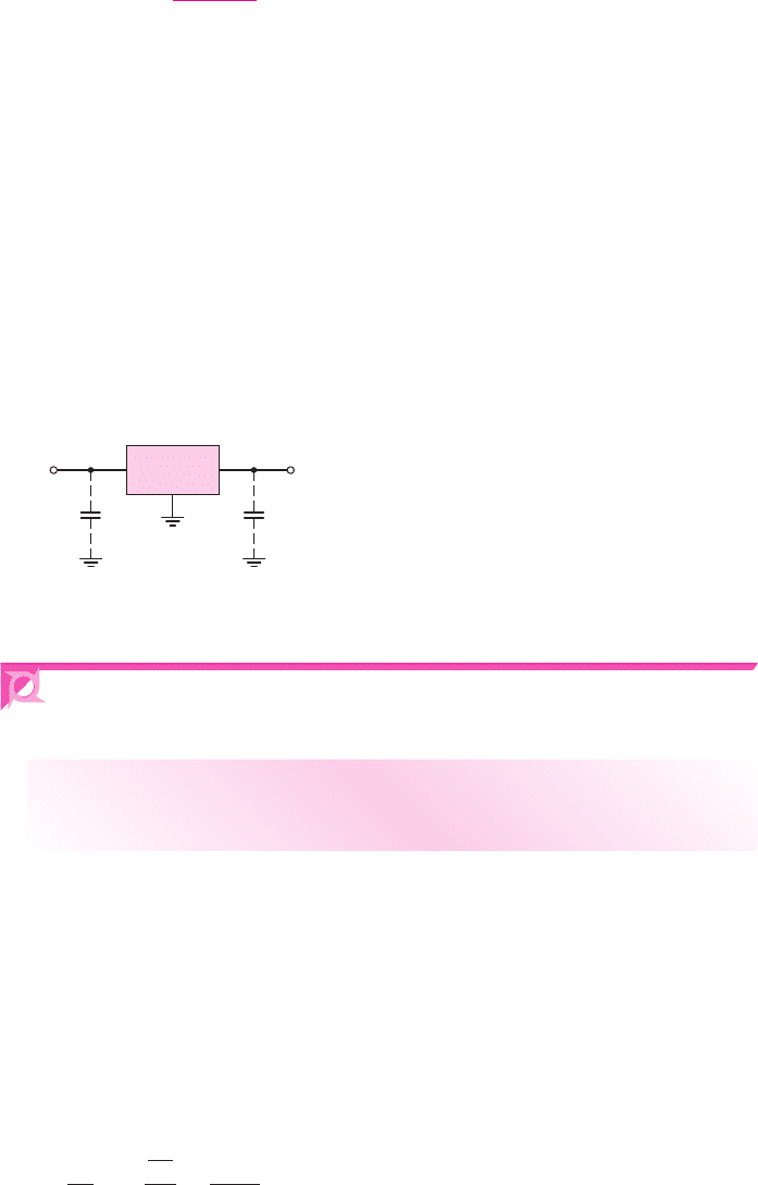
Figure 15.52 shows the basic circuit configuration of a three-terminal regulator. In
some applications, capacitors may be inserted across the input and output terminals.
The lead inductance between the voltage supply and regulator may cause stability
problems. The capacitor across the input terminals is used only if the power supply
and regulator are separated by a few centimeters. The load capacitor may improve the
response of the regulator to transient changes in load current.
C
in
V
+
V
O
C
o
Voltage
regulator
OutputInput
Figure 15.52 Basic circuit configuration of a three-terminal voltage regulator
15.7 DESIGN APPLICATION: AN ACTIVE
BANDPASS FILTER
Objective: • Design an active bandpass filter to meet a set of
specifications.
Specifications: The center frequency of the bandpass amplifier is to be
f
o
= 2 kHz
,
the bandwidth is to be
f = 10 Hz
, and the maximum voltage gain is to be
|A
v
|
max
= 40
.
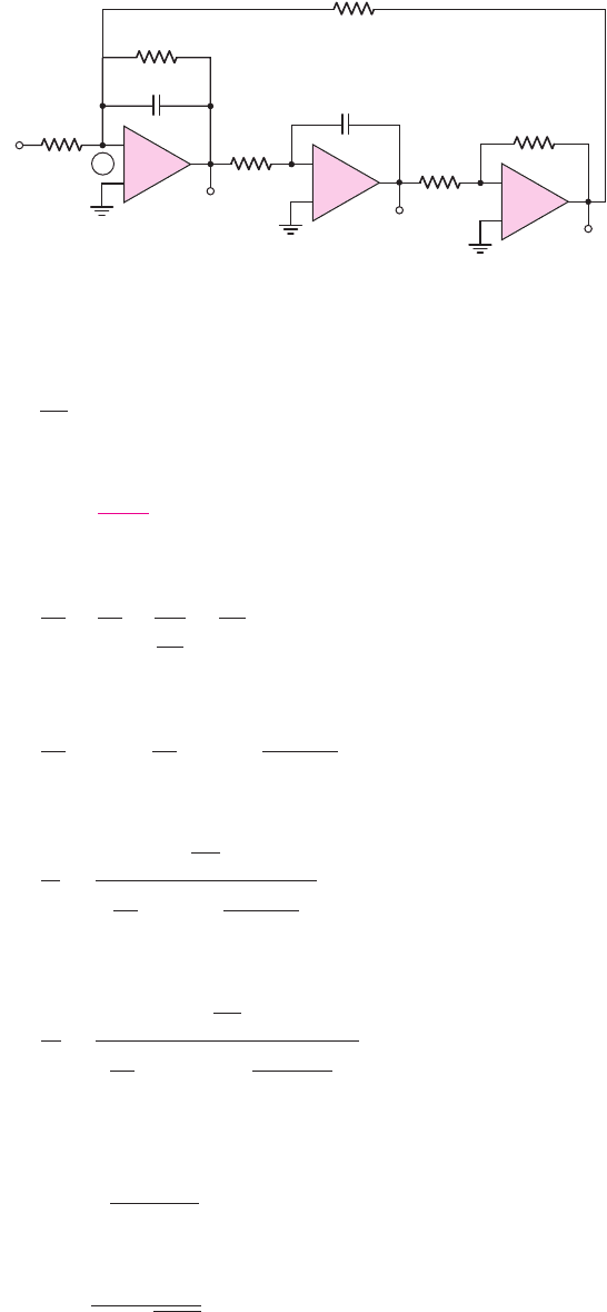
Design Approach: The bandpass amplifier configuration to be designed is shown
in Figure 15.53.
Choices: Ideal op-amps are assumed to be available.
Solution (Analysis): Considering the circuit in Figure 15.53, we have
v
o2
v
o
=−
1
sC
R
2
=
−1
sR
2
C
nea80644_ch15_1061-1140.qxd 07/12/2009 3:59 Page 1122 pinnacle MHDQ-New:MHDQ134:MHDQ134-15:
Chapter 15 Applications and Design of Integrated Circuits 1123
C
C
1
R
1
R
5
R
3
R
2
R
4
v
i
A
1
–
+
v
o
v
o2
v
o3
R
5
A
2
–
+
A
3
–
+
Figure 15.53 Bandpass filter network for the design application
and
v
o3
v
o2
=−1
so
v
o3
=
v
o
sR
2
C
(15.128)
Node 1 is at virtual ground. Summing currents at this node, we find
v
i
R
4
+
v
o
R
1
+
v
o
1
sC
+
v
o3
R
3
= 0
Substituting the expression for
v
o3
from Equation (15.128), we have
v
i
R
4
=−v
o
1
R
1
+sC +
1
sR
2
R
3
C
The overall voltage gain is
v
o
v
i
=
−1
R
4
1
R
1
+sC +
1
sR
2
R
3
C
Setting
s = jω
to obtain the steady-state frequency response, we obtain
v
o
v
i
=
−1
R
4
1
R
1
+ j
ωC −
1
ωR
2
R
3
C
The center frequency occurs at the point where the imaginary term in the denominator
is zero, or
ω
o
C =
1
ω
o
R
2
R
3
C
which can be rewritten as
f
o
=
1
2πC
√
R
2
R
3
nea80644_ch15_1061-1140.qxd 07/12/2009 3:59 Page 1123 pinnacle MHDQ-New:MHDQ134:MHDQ134-15:

1124 Part 2 Analog Electronics
The maximum voltage gain occurs at the center frequency, so that
|A
v
|
max
=
R
1
R
4
The bandwidth is given by
BW =
1
2π R
1
C
Solution (Design): If we let
C = 0.1 μ
F, then we can find
R
1
=
1
2π(BW)C
=
1
2π(10)(0.1 ×10
−6
)
= 159 k
From the maximum gain, we determine
|A
v
|
max
=
R
1
R
4
⇒ 40 =
159
R
4
or
R
4
= 3.975 k
If we choose
R
2
= R
3
, then from the center frequency
f
o
=
1
2πC
√
R
2
R
3
we find
R
2
= R
3
=
1
2π f
o
C
=
1
2π(2 ×10
3
)(0.1 × 10
−6
)
or
R
2
= R
3
= 795.8
Solution (Standard Resistor Values): The closest standard resistor values are
R
2
= 750
,
R
3
= 820
,
R
1
= 160 k
, and
R
4
= 3.9k
. A capacitor of 0.1
μ
F is
a standard value. Using these circuit elements, we find the center frequency to be
f
o
=
1
2πC
√
R
2
R
3
=
1
2π(0.1 ×10
−6
)
√
(750)(820)
or
f
o
= 2.029 kHz
The bandwidth is
BW =
1
2π R
1
C
=
1
2π(160 ×10
3
)(0.1 × 10
−6
)
or
BW = 9.947 Hz
The maximum voltage gain at the center frequency is
|A
v
|
max
=
R
1
R
4
=
160
3.9
= 41.03
nea80644_ch15_1061-1140.qxd 07/12/2009 3:59 Page 1124 pinnacle MHDQ-New:MHDQ134:MHDQ134-15:

Chapter 15 Applications and Design of Integrated Circuits 1125
Comment: Using standard resistor values, the center frequency is within 1.5 per-
cent of the design specification, the bandwidth is within 0.53 percent of the design
specification, and the maximum gain is within 2.6 percent of the design specification.
The circuit elements, of course, have tolerances that will affect the final circuit
performance.
15.8 SUMMARY
• This chapter has presented several applications of op-amps and comparators that
may be fabricated as integrated circuits.
• An active filter uses an active device, such as an op-amp, so as to minimize the
effect of loading on the frequency characteristics of the filter. As an example of
an active filter, Butterworth filter design was considered.
• A switched-capacitor filter offers the advantage of an all-IC configuration, since
this filter uses small capacitance values in conjunction with MOS switching
transistors that simulate large resistance values.
• The basic principles of oscillation are: (1) the net phase through the amplifier
and feedback network must be zero and (2) the magnitude of loop gain must be
unity. For an oscillator to function, the loop gain of a feedback network must
provide sufficient phase shift to produce positive feedback. A phase-shift oscil-
lator, Wien-bridge oscillator, and discrete transistor oscillators were considered.
• A comparator is essentially an op-amp operated in an open-loop configuration.
The output signal is either a high or low saturated voltage.
• A Schmitt trigger uses a comparator with positive feedback, which produces a
hysteresis in the voltage transfer characteristics. This circuit, with its hysteresis
characteristic, can eliminate the chatter effect in an output signal during switch-
ing applications in which noise is superimposed on the input signal. Astable and
monostable multivibrators were considered.
• Examples of IC power amplifiers and voltage regulators were analyzed.
• As an application, an active bandpass filter to meet a set of specifications was
designed.
CHECKPOINT
After studying this chapter, the reader should have the ability to:
✓ Design a basic active filter.
✓ Design a basic oscillator.
✓ Design a basic Schmitt trigger circuit.
✓ Design a Schmitt trigger square-wave oscillator and use a 555 timer circuit.
✓ Understand the operation and characteristics of examples of integrated circuit
power amplifiers.
REVIEW QUESTIONS
1. Describe the difference between an active filter and a passive filter. What is the
primary advantage of an active filter?
2. Sketch the general characteristics of a low-pass filter, a high-pass filter, and a
band-pass filter.
nea80644_ch15_1061-1140.qxd 07/12/2009 3:59 Page 1125 pinnacle MHDQ-New:MHDQ134:MHDQ134-15:

1126 Part 2 Analog Electronics
3. Consider a low-pass filter. What is the slope of the roll-off with frequency for a
(a) one-pole filter, (b) two-pole filter, (c) three-pole filter, and (d) four-pole filter?
4. What characteristic defines a Butterworth filter?
5. Describe how a capacitor in conjunction with two switching transistors can
behave as a resistor.
6. Sketch a one-pole low-pass switched-capacitor filter circuit.
7. Explain the two basic principles that must be satisfied in an oscillator circuit.
8. Describe and explain the operation of a phase-shift oscillator.
9. Describe and explain the operation of a Wien-bridge oscillator.
10. Sketch the circuit and characteristics of a basic inverting Schmitt trigger.
11. What is meant by bistable and astable circuits?
12. What is the primary advantage of a Schmitt trigger circuit.
13. Sketch the circuit and explain the operation of a Schmitt trigger oscillator.
14. Describe how an op-amp in conjunction with a class-AB output stage can be
used as a power amplifier.
15. Sketch a bridge power amplifier and describe its operation.
16. Sketch the basic circuit block diagram of a voltage regulator and explain the
principle of operation.
17. Define load regulation of a voltage regulator.
18. Sketch the basic circuit of a series-pass voltage regulator.
PROBLEMS
Section 15.1 Active Filters
D15.1 (a) Design a single-pole high-pass filter with a gain of 8 in the passband and
a 3 dB frequency of 30 kHz. The maximum resistance is to be 210 k
.
(b) Repeat part (a) for a gain of
−20
in the passband and a 3 dB frequency
of 20 kHz. The minimum input resistance is to be 15 k
.
15.2 Consider a Butterworth low-pass filter. Determine the reduction in gain (in
dB) at
f = 1.5 f
3dB
for a (a) two-pole, (b) three-pole, (c) four-pole, and
(d) five-pole filter.
15.3 The specification in a high-pass Butterworth filter design is that the voltage
transfer function magnitude at
f = 0.9 f
3dB
is 6 dB below the maximum
value. Determine the required order of filter.
D15.4 (a) Design a two-pole high-pass Butterworth active filter with a cutoff fre-
quency at
f
3dB
= 25
kHz and a unity gain magnitude at high frequency.
(b) Determine the magnitude (in dB) of the gain at (i)
f = 22
kHz,
(ii)
f = 25
kHz, and (iii)
f = 28
kHz.
D15.5 (a) Design a three-pole low-pass Butterworth active filter with a cutoff fre-
quency at
f
3dB
= 20
kHz and a unity gain magnitude at low frequency.
(b) Determine the magnitude (in dB) of the gain at (i)
f = 10
kHz,
(ii)
f = 15
kHz, (iii)
f = 20
kHz, (iv)
f = 25
kHz, and (v)
f = 30
kHz.
15.6 Starting with the general transfer function given by Equation (15.7), derive
the relationship between
R
1
and
R
2
in the two-pole high-pass Butterworth
active filter.
15.7 A low-pass Butterworth filter is to be designed such that the magnitude of
the voltage transfer function at
f = 1.2 f
3dB
is 14 dB below the maximum
gain value. Determine the required order of filter.
nea80644_ch15_1061-1140.qxd 07/12/2009 3:59 Page 1126 pinnacle MHDQ-New:MHDQ134:MHDQ134-15:

Chapter 15 Applications and Design of Integrated Circuits 1127
15.8 A high-pass Butterworth filter is to be designed with a cutoff frequency of
f
3dB
= 4
kHz. The gain magnitude is to be reduced by 12 dB at
f = 3
kHz
from the maximum gain value. Determine the required order of filter.
D15.9 A low-pass filter is to be designed to pass frequencies in the 0 to 12 kHz
range. The gain of the amplifier is to be
+10
at the low frequency and
change by no more than 10 percent over the frequency range. In addition,
the gain of the amplifier for frequencies greater than 14 kHz is to be no
greater than 0.1. Determine
f
3-dB
and the number of poles required in a
Butterworth filter.
15.10 Consider a high-pass Butterworth filter. Determine the ratio of the gain
magnitude (in dB) of the filter at a frequency
f = 0.8 f
3dB
compared to the
high-frequency value for a (a) three-pole, (b) five-pole, and (c) seven-pole
filter.
15.11 Consider a low-pass Butterworth filter. Determine the ratio of the gain mag-
nitude (in dB) of the filter at a frequency
f = 1.4 f
3dB
compared to the low-
frequency value for a (a) three-pole, (b) five-pole, and (c) seven-pole filter.
D15.12 Design a special type of first-order filter (one capacitor) in which the gain
magnitude is 25 for frequencies less than approximately 25 kHz and is 1 for
frequencies greater than approximately 25 kHz.
D15.13 An amplitude-modulated radio signal consists of an 80 Hz to 12 kHz audio
signal superimposed on a 770 kHz carrier signal. A low-pass filter is to be
designed in which the gain in the passband is unity and the carrier signal is
attenuated by at least
−100
dB. What order of filter is required?
D15.14 A band-reject filter may be designed by combining a low-pass filter and a
high-pass filter with a summing amplifier. A 60 Hz signal is to be at least
−50
dB below the maximum gain value of 0 dB with a two-pole low-pass
Butterworth filter and a two-pole high-pass Butterworth filter. What is the
bandwidth of the reject filter?
15.15 Consider the bandpass filter in Figure P15.15. (a) Show that the voltage
transfer function is
A
v
(s) =
v
O
v
I
=
−1/R
4
(1/R
1
) + sC + 1/(sCR
2
R
3
)
(b) For
C = 0.1 μF
,
R
1
= 85 k
,
R
2
= R
3
= 300
,
R
4
= 3k
, and
R
5
= 30 k
, determine: (i)
|A
v
(max)|
; (ii) the frequency
f
o
at which
|A
v
(max)|
occurs; and (iii) the two 3 dB frequencies.
*
*
v
I
v
O
C
C
R
1
R
4
R
3
R
2
R
5
R
5
–
+
–
+
–
+
Figure P15.15
nea80644_ch15_1061-1140.qxd 07/12/2009 3:59 Page 1127 pinnacle MHDQ-New:MHDQ134:MHDQ134-15: