Neamen D. Microelectronics: Circuit Analysis and Design
Подождите немного. Документ загружается.

1108 Part 2 Analog Electronics
negative feedback incorporated on the chip, while others use a current gain output
stage and negative feedback external to the chip. We consider three examples of IC
power amplifiers in this section.
LM380 Power Amplifier
The LM380 is a popular fixed-gain power amplifier capable of an ac power output up
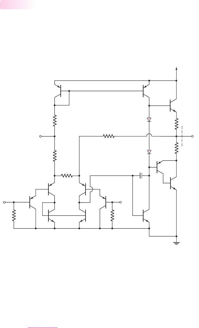
to 5 W. Figure 15.42 is a simplified circuit diagram of the amplifier. The input stage
is a Darlington pair configuration composed of
Q
1
through
Q
4
and an active load
formed by
Q
5
and
Q
6
.
15.5.1
–ln (6)
Q
1
Q
3
Q
4
Q
9
Q
8
Q
7
Q
11
Q
10
D
2
D
1
Q
2
Q
12
Q
5
Q
6
R
4
150 kΩ
R
3
1 kΩ
R
5
150 kΩ
R
7
0.5 Ω
R
6
0.5 Ω
R
1B
25 kΩ
R
1A
25 kΩ
R
2
25 kΩ
+ln
(2)
(7) Ground
C
F
Output
(8)
V
+
(14)
Bypass
(1)
Figure 15.42 The LM380 power amplifier
The input stage is biased by currents through resistors
R
1A
,
R
1B
, and
R
2
. Tran-
sistor
Q
3
is biased by a current from power supply
V
+
, through the diode-connected
transistor
Q
10
and resistors
R
1A
and
R
1B
. Transistor
Q
4
is biased by a current from
the output terminal through
R
2
. For zero input voltages, the currents in
Q
3
and
Q
4
are nearly equal. Assuming matched input transistors and neglecting base currents,
we find that
I
C3
=
V
+
−3V
EB
R
1A
+ R
2A
(15.106)
nea80644_ch15_1061-1140.qxd 07/12/2009 3:58 Page 1108 pinnacle MHDQ-New:MHDQ134:MHDQ134-15:
Chapter 15 Applications and Design of Integrated Circuits 1109
and
I
C4
=
V
O
−2V
EB
R
2
(15.107)
Since
I
C3
= I
C4
, we can find the quiescent output voltage by combining Equa-
tions (15.106) and (15.107), or
V
O
= 2V
EB
+
R
2
R
1A
+ R
2B
(V
+
−3V
EB
) =
1
2
V
+
+
1
2
V
EB
(15.108)
The quiescent output voltage is approximately half the power supply voltage,
which allows for a maximum output voltage swing and for maximum power to be de-
livered to a load. The feedback from the output to the emitter of
Q
4
, through
R
2
, sta-
bilizes the quiescent output voltage at this value.
The output signal of the diff-amp is the input signal to the base of
Q
12
,which is
connected in a common-emitter configuration in which
Q
11
acts as an active load.
The output signal from the collector of
Q
12
is the input to the class-AB output stage,
and capacitor
C
F
provides frequency compensation.
The class-AB complementary push-pull emitter-follower output stage comprises
transistors
Q
7
,
Q
8
, and
Q
9
and diodes
D
1
and
D
2
. Transistor
Q
7
, which is the npn
half of the push-pull output stage, sources current to the load. Transistors
Q
8
and
Q
9
operate as a composite pnp transistor, with the overall current gain equal to the prod-
uct of the current gains of each transistor. This composite transistor is the pnp half of
the push-pull output stage sinking current from the load. Diodes
D
1
and
D
2
provide
the quiescent bias for class-AB operation.
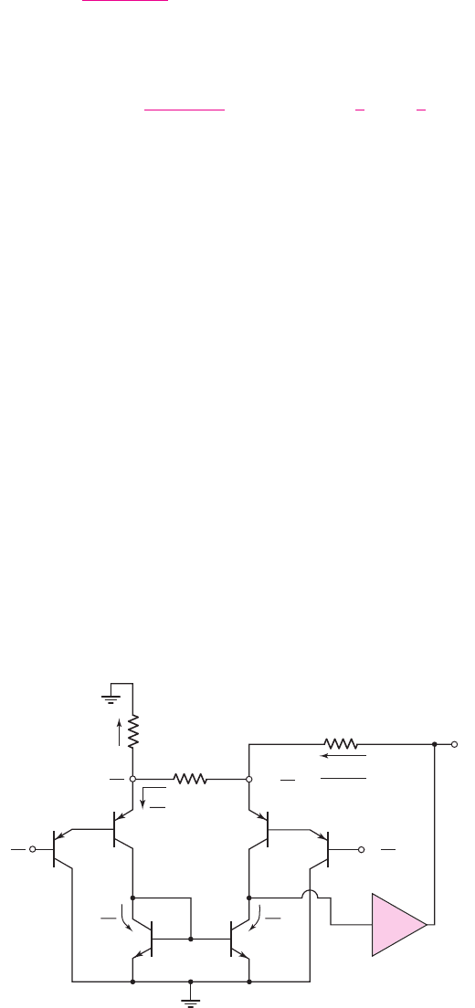
The closed-loop gain is determined from the ac equivalent circuit in Figure 15.43.
A differential-input voltage is applied at the input, with
V
id
/2
applied at the nonin-
verting terminal and
−V
id
/2
applied at the inverting terminal. An external bypass ca-
pacitor is connected at the node between
R
1A
and
R
1B
, putting this node at signal
ground. The second stage and output stage are represented by amplifier
A
. The input
impedance is assumed to be large, which means that the input current is assumed to
be negligible.
V
id
R
3
V
id
R
3
V
id
R
3
V
o
– V
i
/2
R
2
R
2
Q
1
Q
3
Q
4
Q
2
Q
5
Q
6
R
3
= 1 kΩ
R
1B
=
25 kΩ
V
id
2
≈ –
V
id
2
≈ +
V
id
2
+
V
id
2
–
i ≈ o
i ≈ o
V
o
A
Figure 15.43 The ac equivalent circuit, LM380 power amplifier
nea80644_ch15_1061-1140.qxd 07/12/2009 3:58 Page 1109 pinnacle MHDQ-New:MHDQ134:MHDQ134-15:
1110 Part 2 Analog Electronics
Since the input stage is an emitter-follower configuration, the signal voltage is
approximately
+V
id
/2
at the emitter of
Q
4
and is approximately
−V
id
/2
at the emit-
ter of
Q
3
. Comparing the resistor values of
R
3
and
R
1B
, we see the signal current
in
R
1B
is negligible. The signal current in
Q
3
is equal to that in
R
3
, and the current-
mirror configuration of
Q
5
and
Q
6
implies that the current in
Q
6
is also
V
id
/R
3
.
Summing the currents at the emitter of
Q
4
, we obtain
V
o
− V
id
/2
R
2
=
V
id
R
3
+
V
id
R
3
(15.109)
which yields the closed-loop voltage gain
V
o
V
id
=
1
2
+
2R
2
R
3
∼
=
50
(15.110)
Equation (15.110) shows that the LM380 has a fixed gain of approximately 50.
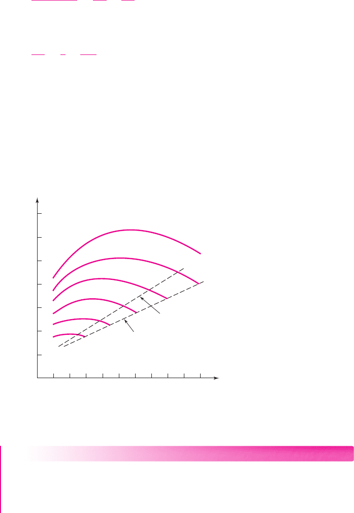
The LM380 is designed to operate in the range of 12–22 V from a single supply
V
+
. The value of
V
+
depends on the power requirements. Figure 15.44 shows the
relationship between device dissipation, output power, and supply voltage for an
8
load. As the output signal increases, harmonic distortion in the sinusoidal signal in-
creases because the output transistor is approaching the saturation region. The lines
marked 3% and 10% are the points at which harmonic distortion reaches 3% and
10%, respectively.
0 0.5 1.0 1.5 2.0 2.5
Output power (W)
Device dissipation (W)
3.0 3.5 4.0 4.5 5.0
0.5
1.0
1.5
2.0
2.5
3.0
3.5
12 V
14 V
16 V
18 V
20 V
22 V
3% distortion level
10% distortion level
V
+
Figure 15.44 LM380 power amplifier characteristics
EXAMPLE 15.12
Objective: Determine the output voltage and conversion efficiency for an LM380
power amplifier.
The required power for an
8
is to be 4 W, with minimum distortion in the out-
put signal.
nea80644_ch15_1061-1140.qxd 07/12/2009 3:58 Page 1110 pinnacle MHDQ-New:MHDQ134:MHDQ134-15:

Chapter 15 Applications and Design of Integrated Circuits 1111
Solution:
From the curves in Figure 15.44, for an output of 4 W, minimum distortion
occurs when the supply voltage is a maximum, or
V
+
= 22 V
. For 4 W to be deliv-
ered to the
8
load, the peak output signal voltage is determined by
¯
P
L
= 4 =
V
2
P
2R
L
=
V
2
P
2(8)
which yields
V
P
= 8V
.
The power dissipated in the device is 3 W, which means that the conversion
efficiency is
4/(3 + 4) → 57
percent.
Comment: A reduction in the harmonic distortion means that the conversion effi-
ciency is less than the theoretical value of 78.5 percent for the class-B output stages.
However, a conversion efficiency of 57 percent is still substantially larger than would
be obtained in any class-A amplifier.
EXERCISE PROBLEM
Ex 15.12: The supply voltage to an LM380 power amplifier, as shown in Fig-
ure 15.42, is 12 V. With a sinusoidal input signal, an average output power of 1 W
must be delivered to an 8
load. (a) Determine the peak output voltage and peak
output current. (b) When the output voltage is at its peak value, calculate the
instantaneous power being dissipated in
Q
7
. (Ans. (a)
V
P
= 4V
,
I
p
= 0.5A
(b)
P
Q
= 4W
)
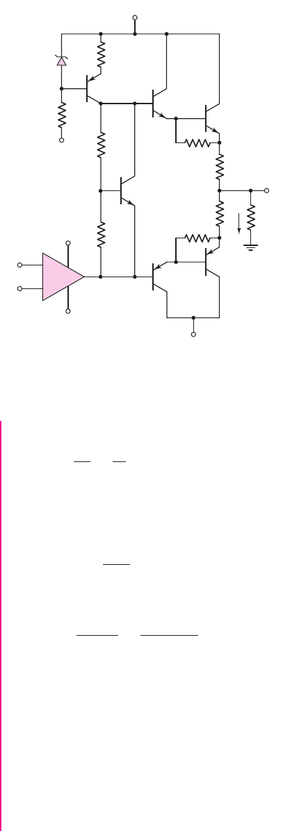
PA12 Power Amplifier
The basic circuit diagram of the PA12 amplifier is shown in Figure 15.45. The
input signal to the class-AB output stage is from a small-signal high-gain op-amp.
The power supply voltages are in the range of
10 ≤ V
S
≤ 50 V
, the peak output
current is in the range
−15 ≤ I
L
≤+15 A
, and the maximum internal power dis-
sipation is 125 W. The output stage is a class-AB configuration using npn and pnp
Darlington pair transistors. The bias for the output transistors is established by the
V
BE
multiplier circuit composed of
R
1
, R
2
, and
Q
4
. Also, external feedback is
required.
DESIGN EXAMPLE 15.13
Objective: Design the supply voltage required in the PA12 power amplifier to meet
a specific conversion efficiency.
Specifications: The circuit with the configuration in Figure 15.45 has a load resis-
tance of 10
. The required average power delivered to the load is 20 W. Determine
the power supply voltage such that the conversion efficiency is 50 percent.
Choices: The circuit shown in Figure 15.45 is available.
Solution: For an average of 20 W delivered to the load, the peak output voltage is
V
p
=
2R
L
¯
P
L
=
2(10)(20) = 20 V
15.5.2
nea80644_ch15_1061-1140.qxd 07/12/2009 3:58 Page 1111 pinnacle MHDQ-New:MHDQ134:MHDQ134-15:
1112 Part 2 Analog Electronics
and the peak load current is
I
p
=
V
p
R
L
=
20
10
= 2A
Assuming an ideal class-B condition, for a 50 percent conversion efficiency, the
average power supplied by each
V
S
source must be 20 W. If we neglect power dissi-
pation in the bias circuit, the average power supplied by each source is
P
S
= V
S
V
p
π R
L
and the required supply voltage is then
V
S
=
π R
L
P
S
V
p
=
π(10)(20)
20
= 31.4V
Trade-offs: The required power supply must also be able to deliver the required cur-
rent. For a power of 20 W delivered to the 10
load, the load current (rms value) by
itself is 1.41 A.
Comment: The actual conversion efficiency for class-AB operation is less than
50 percent. This reduced conversion efficiency ensures that harmonic distortion in
the output signal is not severe.
Computer Simulation Verification: A computer simulation analysis of the circuit in
Figure 15.45 was performed. The supply voltages were set at
±31.4
V and the input si-
nusoidal signal was adjusted so that the peak sinusoidal output voltage was 19.7 V
i
L
V
S
–V
S
+V
S
–V
S
–V
S
R
CL
R
CL
R
E1
R
L
R
R
1
D
2
Q
4
Q
1
Q
6A
Q
2A
Q
6B
Q
2B
R
2
R
3
R
4
v
O
–
+
Figure 15.45 PA12 power amplifier
nea80644_ch15_1061-1140.qxd 07/12/2009 3:58 Page 1112 pinnacle MHDQ-New:MHDQ134:MHDQ134-15:
Chapter 15 Applications and Design of Integrated Circuits 1113
across a 10
load resistor. For these settings, the bias supply currents were 1.971 A. The
average power delivered by the supply voltage sources is 39.4 W, so that the conversion
efficiency is 49.25 percent, which is just slightly below the design value of 50 percent.
EXERCISE PROBLEM
Ex 15.13: Consider the power amplifier in Figure 15.45. (a) Assume a load
resistance of
R
L
= 20
that must dissipate
P
L
= 5
W is connected to the
output. Determine (i) the values
V
p
and
I
p
for the load and (ii) the required
power supply voltage
V
S
. (b) Repeat part (a) for
R
L
= 8
and
P
L
= 10
W.
(Ans. (a) (i)
V
p
= 14.14
V,
I
p
= 0.707
A; (ii)
V
S
= 22.2
V; (b) (i)
V
p
= 12.65
V,
I
p
= 1.58
A; (ii)
V
S
= 19.9
V)
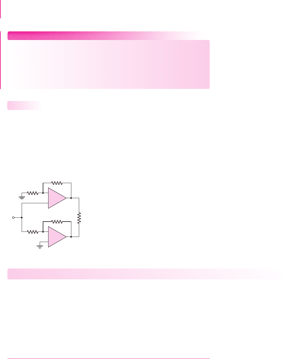
Bridge Power Amplifier
Figure 15.46 shows a bridge power amplifier that uses two op-amps. Amplifier
A
1
is
connected in a noninverting configuration;
A
2
is connected in an inverting configura-
tion. The magnitudes of the two gains are equal to each other. The load, such as an
audio speaker, is connected between the two output terminals and is floating. A
sinusoidal input signal produces output voltages
v
o1
and
v
o2
, which are equal in mag-
nitude but 180 degrees out of phase. The voltage across the load is therefore twice as
large as it would be if produced from a single op-amp.
15.5.3
–
+
–
+
v
I
R
L
v
O1
v
O2
R
2
R
4
R
1
R
3
A
2
A
1
Figure 15.46 Bridge power amplifier
Test Your Understanding
TYU 15.13 (a) Consider the bridge amplifier in Figure 15.46 with parameters
R
1
= R
3
= 20
k
,
R
2
= 40
k
,
R
4
= 60
k
, and
R
L
= 500
. Assume the op-
amps are biased at
±15
V and the peak output voltage of each op-amp is limited to
±12
V. Determine (i) the voltage gain of each op-amp circuit, (ii) the average power
that can be delivered to the load, and (iii) the peak amplitude of the input voltage
v
I
.
(b) From the results of part (a), change the values of
R
2
and
R
4
such that the same av-
erage power is delivered to the load but the magnitude of the required input voltage
is cut in half. What are the required amplifier gains? (Ans. (a) (i)
A
v1
=+3
,
A
v2
=−3
, (ii)
¯
P
L
= 0.576
W, (iii)
v
I
= 4
V; (b)
R
2
= 100
k
,
R
4
= 120
k
,
A
v1
=+6
,
A
v2
=−6)
nea80644_ch15_1061-1140.qxd 07/12/2009 3:58 Page 1113 pinnacle MHDQ-New:MHDQ134:MHDQ134-15:

1114 Part 2 Analog Electronics
15.6 VOLTAGE REGULATORS
Objective: • Analyze and design voltage regulators that establish a
relatively constant dc voltage generated from an ac signal source.
Another class of analog circuits that is used extensively in electronic systems is
the voltage regulator. We briefly considered constant-voltage circuits, or voltage
regulators, when we studied diode circuits and when we considered ideal op-amp
circuits in Chapter 9. In this section, we will discuss examples of IC voltage
regulators.
Basic Regulator Description
A voltage regulator is a circuit or device that provides a constant voltage to a load.
The output voltage is controlled by the internal circuitry and is relatively independent
of the load current supplied by the regulator.
A basic diagram of a voltage regulator is shown in Figure 15.47. It consists of
three basic parts: a reference voltage circuit; an error amplifier, which is part of a
feedback circuit; and a current amplifier, which supplies the required load current.
The reference voltage circuit produces a voltage that is essentially independent of
both supply voltage
V
+
and temperature. As shown in the basic circuit of Figure
15.47, a fraction of the output voltage is fed back to the error amplifier which,
through negative feedback, maintains the feedback voltage at a value equal to the ref-
erence voltage.
15.6.1
V
O
Current
amplifier
Reference
voltage
R
L
Error
amplifier
+
–
I
O
b
Figure 15.47 Basic circuit diagram of a voltage regulator
Since the regulator output voltage is derived from the reference voltage, any
variation in that reference voltage, as the power supply voltage
V
+
changes, also af-
fects the output voltage. Line regulation is defined as the ratio of the change in out-
put voltage to a given change in the input supply voltage, or
Line regulation =
V
o
V
+
(15.111)
Line regulation is one figure of merit of voltage regulators. In many cases, the refer-
ence voltage circuit contains one or more Zener diodes. Line regulation is then a
function of the Zener diode resistance and the effective resistance of the circuit bias-
ing the diode.
nea80644_ch15_1061-1140.qxd 07/12/2009 3:58 Page 1114 pinnacle MHDQ-New:MHDQ134:MHDQ134-15:

Chapter 15 Applications and Design of Integrated Circuits 1115
Output Resistance and Load Regulation
The ideal voltage regulator is equivalent to an ideal voltage source in that the output
voltage is independent of the output current and any output load impedance. In actual
voltage regulators, however, the output voltage is a slight function of output current.
This dependence is related to the output resistance of the regulator.
The output resistance is defined as the rate of change of output voltage with out-
put current, or
R
of
=−
V
O
I
O
(15.112)
The change in
V
O
and
I
O
is caused by a change in the load resistance
R
L
. Every-
thing else in the circuit remains constant. The negative sign in Equation (15.112)
results from the voltage polarity and current direction, as shown in Figure 15.47. An
increase in
I
O
produces a decrease in
V
O
; therefore, the output resistance
R
of
is pos-
itive. The output resistance of a voltage regulator should be small, so that a change in
output current
I
O
will result in only a small change in output voltage
V
O
.
The notation
R
of
for the output resistance of the voltage regulator is the same as
the term for the output resistance of a feedback circuit. This is appropriate since volt-
age regulators use feedback.
A second figure-of-merit for voltage regulators is load regulation. Load regulation
is defined as the change in output voltage between a no-load current condition and a full-
load current condition. Load regulation can be expressed as a percentage, or
Load regulation =
V
O
(NL) − V
O
(FL)
V
O
(NL)
×100%
(15.113)
where
V
O
(NL) is the output voltage for a zero-load current condition and
V
O
(FL) is
the output voltage for a full-load or maximum load current condition.
In some applications, a zero-load current is impractical, and a load current that
is approximately 1 percent of the full-load current is used as the no-load condition.
In most cases, this condition provides an adequate definition for load regulation.
EXAMPLE 15.14
Objective: Determine the output resistance and load regulation of a voltage regulator.
Assume the output voltage of a regulator is 5.0 V for a load current of 5 mA, and
is 4.96 V for a load current of 1.5 A.
Solution: If we assume that the output voltage decreases linearly with load current,
then the output resistance is
R
of
=−
V
O
I
O
=−
5.0 − 4.96
0.005 − 1.5
∼
=
0.0267
or
R
of
∼
=
27 m
The load regulation is then
Load regulation =
V
O
(NL) −V
O
(FL)
V
O
(NL)
×100% =
5.0 −4.96
5.0
×100% = 0.80%
15.6.2
nea80644_ch15_1061-1140.qxd 07/12/2009 3:58 Page 1115 pinnacle MHDQ-New:MHDQ134:MHDQ134-15:
1116 Part 2 Analog Electronics
Comment: The output resistance of a voltage regulator is usually not constant at all
load currents, but the values are typically in the milliohm range. Also, a load regula-
tion of 0.8% is typical of many voltage regulators.
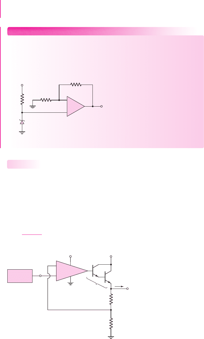
EXERCISE PROBLEM
Ex 15.14: The reference voltage for a constant-voltage source is established by
the simple combination of
V
+
,
R
1
, and
D
I
, as shown in the regulator circuit in
Figure 15.48. If the Zener diode resistance is
R
Z
= 10
and the zero-current
diode voltage is
V
Zo
= 5.6V
, determine the line regulation of the voltage regula-
tor. Assume an ideal op-amp. (Ans. 0.454%)
+
–
V
Z
D
1
V
O
10 kΩ
10 kΩ
R
1
=
4.4 kΩ
V
+
–
+
Figure 15.48 Figure for Exercise Ex15.14
Simple Series-Pass Regulator
Figure 15.49 shows a simple voltage regulator that includes an error amplifier (com-
parator) and series-pass transistors. The series-pass transistors, which are connected
in a Darlington emitter-follower configuration, form the current amplifier. A resistive
voltage divider allows a portion of the output voltage to be fed back to the error am-
plifier. The closed-loop feedback system acts to maintain this fraction of the output
voltage at a value equal to the reference voltage.
For an ideal system, we can write
R
2
R
1
+ R
2
V
O
= V
REF
(15.114(a))
15.6.3
V
O
V
+
V
+
Reference
voltage
R
2
R
1
I
O
+
–
Error
amplifier
Series-pass
transistors
Q
2
Q
1
V
REF
Figure 15.49 Basic series-pass voltage regulator
nea80644_ch15_1061-1140.qxd 07/12/2009 3:58 Page 1116 pinnacle MHDQ-New:MHDQ134:MHDQ134-15:

Chapter 15 Applications and Design of Integrated Circuits 1117
or
V
O
= V
REF
1 +
R
1
R
2
(15.114(b))
Since the output of the feedback circuit is a shunt connection, the output resis-
tance can be written, according to the results from Chapter 12, as
R
of
=
R
o
1 + T
(15.115)
where
R
o
is the output resistance of the open-loop system and
T
is the loop gain.
From feedback theory, the closed-loop and open-loop gains are related by
A
CL
=
A
OL
1 + T
(15.116)
Combining Equation (15.115) and (15.116), we can write the closed-loop output
resistance of the voltage regulator in the form
R
of
= R
o
A
CL
A
OL
(15.117)
From the circuit in Figure 15.49, the closed-loop gain is
A
CL
=
V
O
V
REF
(15.118)
The open-loop output resistance is the output resistance of the series-pass tran-
sistors, which are operating in an emitter-follower configuration. From previous
results, we can write
R
o
=
r
π2
+ R
o1
(1 + β
2
)
(15.119)
where
R
o1
=
r
π1
+ R
oa
(1 + β
1
)
(15.120)
in which
R
oa
is the output resistance of the error amplifier. If the current in
Q
2
is
essentially equal to
I
O
and if
β
1
and
β
2
are large, then combining Equations (15.119)
and (15.120) yields
R
o
∼
=
2V
T
I
O
+
R
oa
β
1
β
2
(15.121)
Since the product
β
1
β
2
is large, the second term in Equation (15.121) is generally
negligible.
The closed-loop output resistance, given by Equation (15.117), is then
R
of
∼
=
2V
T
I
O
A
CL
A
OL
=
2V
T
I
O
V
O
V
REF
1
A
OL
(15.122)
Equation (15.122) shows that the output resistance of the voltage regulator is not
constant, but varies inversely with load current. Also, for very small values of load
current, the output resistance may be unacceptably high.
The basic definition of output resistance is given in Equation (15.112). Using
this definition and Equation (15.122), and rearranging terms, we obtain
V
O
V
O
=−
I
O
I
O
2V
T
R
REF
1
A
OL
(15.123)
nea80644_ch15_1061-1140.qxd 07/12/2009 3:58 Page 1117 pinnacle MHDQ-New:MHDQ134:MHDQ134-15: