Neamen D. Microelectronics: Circuit Analysis and Design
Подождите немного. Документ загружается.

1128 Part 2 Analog Electronics
15.16 Consider the circuit in Figure P15.16. (a) Derive the expressions for the
magnitude and phase of the voltage transfer function. (b) Plot the phase ver-
sus frequency for
R = 10 k
and
C = 15.9nF
. [Note: this filter is referred
to as an all-pass filter in that the magnitude of the voltage gain is constant,
but the phase of the output voltage changes with frequency.]
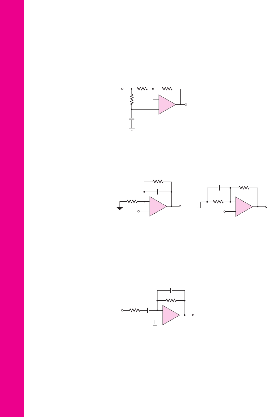
15.17 For each of the circuits in Figures P15.17, derive the expressions for the volt-
age transfer function
T (s) =V
o
(s)/ V
i
(s)
and the cutoff frequency f
3 dB
.
V
i
V
o
R
1
R
2
C
V
i
V
o
R
1
R
2
C
(a) (b)
–
+
–
+
Figure P15.17
V
i
V
o
R
1
C
1
C
2
R
2
–
+
Figure P15.18
v
I
v
O
R
R
C
R
–
+
Figure P15.16
15.18 The circuit in Figure P15.18 is a bandpass filter. (a) Derive the expression
for the voltage transfer function
T (s)
. (b) If
R
1
= 10 k
, determine
R
2
,
C
1
,
and
C
2
such that the magnitude of the midband gain is 50 and the cutoff fre-
quencies are 200 Hz and 5 kHz.
15.19 A simple bandpass filter can be designed by cascading one-pole high-pass
and one-pole low-pass filters. Using op-amp circuits similar to those in
Figure 15.3, design a bandpass filter with cutoff frequencies of 150 Hz and
20 kHz and with a midband gain of 30 dB. Resistor values must be no larger
than 250 k
, but the input resistance must be as large as possible.
nea80644_ch15_1061-1140.qxd 07/12/2009 3:59 Page 1128 pinnacle MHDQ-New:MHDQ134:MHDQ134-15:

Chapter 15 Applications and Design of Integrated Circuits 1129
15.20 The clock frequency in the switched-capacitor circuit in Figure 15.12(a) is
f
C
= 50
kHz. Find the equivalent resistance that is simulated when
(a)
C = 0.5
pF, (b)
C = 2
pF, and (c)
C = 10
pF.
15.21 In the switched-capacitor circuit in Figure 15.12(a), the voltages are
V
1
= 2V
and
V
2
= 1V
, the capacitor value is
C = 10 pF
, and the clock
frequency is
f
C
= 100 kHz
. (a) Determine the charge transferred from
V
1
to
V
2
during each clock pulse. (b) What is the average current that source
V
1
supplies? (c) If the “on” resistance of each MOSFET is 1000
, determine
the time required to transfer 99 percent of the charge during each half-clock
period.
D15.22 Consider the switched-capacitor filter in Figure 15.13(b). Design the circuit
for a low-frequency gain of
−10
and a cutoff frequency of 10 kHz. The
clock frequency must be 10 times the cutoff frequency and the largest ca-
pacitance is to be 30 pF. Find the required values of
C
1
,
C
2
, and
C
F
.
15.23 The circuit in Figure P15.23 is a switched-capacitor integrator. Let
C
F
=
30 pF
and
C
1
= 5pF
, and assume the clock frequency is 100 kHz. Also, let
v
I
= 1V
. (a) Determine the integrating
RC
time constant. (b) Find the
change in output voltage during each clock period. (c) If
C
F
is initially un-
charged, how many clock pulses are required for
v
O
to change by 13 V?
Section 15.2 Oscillators
15.24 Consider the phase shift oscillator in Figure 15.15. (a) For
R = 20
k
and
C = 0.001 μ
F, determine the frequency of oscillation. What is the required
value of
R
2
? (b) Design the circuit such that the frequency of oscillation is
f
o
= 25
kHz. Let
R = 20
k
.
15.25 In the phase-shift oscillator in Figure 15.15, the capacitor at the noninvert-
ing terminal of op-amp
A
1
is replaced by a variable capacitor
C
V
. (a) Derive
the expression for the frequency of oscillation. (b) If
C =10 pF
,
R =10 k
,
and
C
V
is variable between 10 and 50 pF, determine the range of oscillation
frequency.
15.26 Consider the phase shift oscillator in Figure 15.16. (a) Determine the fre-
quency of oscillation for
R = 12
k
and
C = 150
pF. What is the required
value of
R
2
? (b) Design the circuit such that the frequency of oscillation is
f
o
= 22
kHz. Let
C = 0.001 μ
F.
15.27 Analyze the phase-shift oscillator in Figure 15.16. Show that the frequency
of oscillation is given by Equation (15.46) and that the condition for oscil-
lation is given by Equation (15.47).
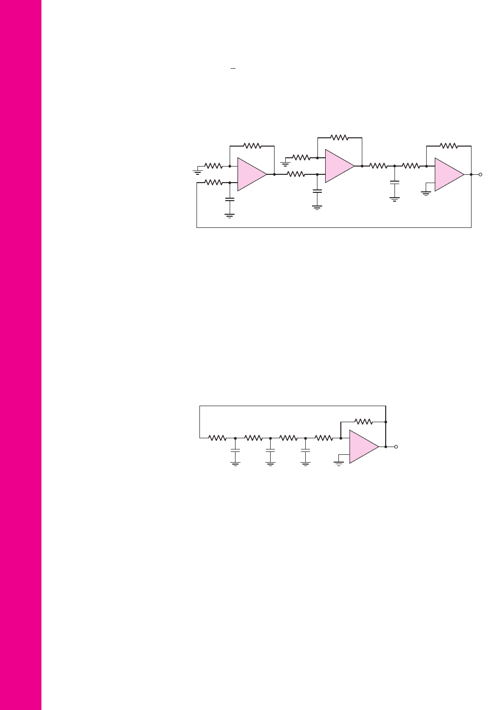
15.28 The circuit in Figure P15.28 is an alternative configuration of a phase-
shift oscillator. (a) Assume that
R
1
= R
2
= R
3
= R
A
1
= R
A
2
= R
A
3
≡ R
and
C
1
= C
2
=C
3
≡C
. Show that the frequency of oscillation is
v
I
v
O
C
F
C
1
f
1
f
2
–
+
Figure P15.23
nea80644_ch15_1061-1140.qxd 07/12/2009 3:59 Page 1129 pinnacle MHDQ-New:MHDQ134:MHDQ134-15:
1130 Part 2 Analog Electronics
ω
o
=
√
3/RC
. (b) Assume equal magnitudes of gain in each amplifier
stage. What is the minimum magnitude of gain required in each stage to
sustain oscillation?
–
+
–
+
–
+
R
A1
R
A2
R
F2
R
F3
R
F1
R
1
R
2
C
1
C
2
C
3
v
O
R
A3
R
3
A
1
A
2
A
3
Figure P15.28
R
F
RRRR
CCC
v
O
–
+
Figure P15.30
*15.29 In the circuit in Figure P15.28, let
R
F1
= R
F2
= R
F3
≡ R
F
,
R
2
= R
3
= R
A1
= R
A2
= R
A3
≡ R
,
C
1
= C
2
= C
3
≡ C
, and let
R
1
be a
variable resistance
R
1
= R
V
. (a) Derive the expression for the frequency of
oscillation. (b) If
R
V
= R
, determine the condition for oscillation. (c) Using
the results of part (a), determine the range in the frequency of oscillation for
R = 25
k
,
C = 0.001 μ
F, and
15 ≤ R
V
≤ 30
k
.
*15.30 Consider the phase-shift oscillator in Figure P15.30. (a) Derive the expres-
sion for the frequency of oscillation. (b) Determine the condition for oscil-
lation. (c) For
R = 20
k
, find
C
and
R
F
that will produce sustained oscil-
lations at
f
o
= 22
kHz.
*15.31 Consider the phase-shift oscillator in Figure P15.30. (a) Assume the first re-
sistor that is connected to
v
o
is a variable resistor
R
V
. Derive the expression
for the frequency of oscillation in terms of
C
,
R
, and
R
V
. (b) Using the re-
sults of part (a), determine the range in the frequency of oscillation for
R = 25
k
,
C = 0.001 μ
F, and
15 ≤ R
V
≤ 30
k
.
15.32 A Wien-bridge oscillator is shown in Figure P15.32. (a) Derive the expres-
sion for the frequency of oscillation. (b) What is the condition for sustained
oscillations?
15.33 Consider the oscillator circuit in Figure P15.33. (a) Derive the expression
for the loop gain T(s). (b) Determine the expression for the frequency of
oscillation. (c) Find the condition for oscillation.
nea80644_ch15_1061-1140.qxd 07/12/2009 3:59 Page 1130 pinnacle MHDQ-New:MHDQ134:MHDQ134-15:
Chapter 15 Applications and Design of Integrated Circuits 1131
D15.34 Design the Wein-bridge oscillator in Figure 15.17 to oscillate at
f
o
= 35
kHz.
Choose appropriate component values.
D15.35 The Colpitts oscillator in Figure 15.19 is biased at
I
D
= 0.8
mA. The tran-
sistor parameters are
V
TN
= 0.8
V and
K
n
= 0.7
mA/V
2
. Let
C
1
= 0.02 μ
F
and
R = 2
k
. Design the circuit to oscillate at
f
o
= 350
kHz.
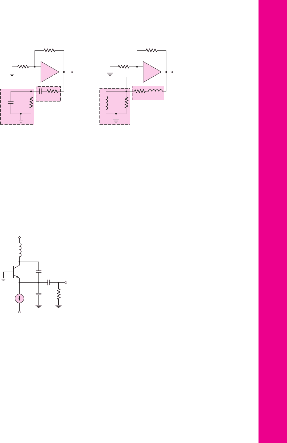
15.36 Figure P15.36 shows a Colpitts oscillator with a BJT. Assume
r
π
and
r
o
are
both very large. Derive the expressions for the frequency of oscillation and
the condition of oscillation.
+
–
R
1
R
2
v
O
C
A
R
B
C
B
R
A
Figure P15.32
+
–
R
1
R
2
v
O
L
R
L
R
Figure P15.33
V
+
V
–
L
C
1
C
2
R
L
v
O
I
C → ∞
Figure P15.36
15.37 Consider the ac equivalent circuit of the Hartley oscillator in Figure 15.21.
(a) Derive the expression for the frequency of oscillation. (b) Determine the
condition for sustained oscillations.
D15.38 For the Hartley oscillator in Figure 15.21, assume
r
π
→∞
and let
g
m
= 30
mA/V. (a) Derive the expression for the frequency of oscillation.
(b) Show that the condition for oscillation is given by
g
m
R = L
1
/L
2
.
(c) Design the circuit to oscillate at
f
o
= 750
kHz for
L
1
= L
2
= 50 μ
H.
*
nea80644_ch15_1061-1140.qxd 07/12/2009 3:59 Page 1131 pinnacle MHDQ-New:MHDQ134:MHDQ134-15:

1132 Part 2 Analog Electronics
15.39 Find the loop gain functions
T (s)
and
T ( jω)
, the frequency of oscillation,
and the
R
2
/R
1
required for oscillation for the circuit in Figure P15.39.
15.40 Repeat Problem 15.39 for the circuit in Figure P15.40.
15.41 Repeat Problem 15.39 for the circuit in Figure P15.41.
Section 15.3 Schmitt Trigger Circuits
15.42 For the comparator in the circuit in Figure 15.26(a), the output saturation
voltages are
±9
V. Let
V
REF
= 5
V. Let
R
2
be a fixed resistor in series with
a potentiometer. Design the circuit such that the crossover voltage can eas-
ily be varied over the range of
−2
V to
−4
V. The minimum resistance is to
be 20 k
.
15.43 Consider the Schmitt trigger shown in Figure 15.29(a). Assume the satu-
rated output voltages are
V
H
=+10
V and
V
L
=−10
V. The range of the
input voltage is
−5 ≤ v
I
≤ 5
V. Design the circuit such that the hysteresis
width is 0.4 V and the maximum current in any resistor is 0.20 mA.
15.44 The saturated output voltages of the Schmitt trigger in Figure 15.28(a) are
V
H
=+9
V and
V
L
=−9
V. The range of the input voltage is
−9 ≤ v
I
≤ 9
V. (a) Design the circuit whose minimum resistance is 2 k
and such that the hysteresis width is 0.2 V. (b) Using the results of part (a),
determine the maximum current in the resistors.
15.45 A Schmitt trigger circuit is shown in Figure 15.28(a). The parameters are
V
H
=+10
V,
V
L
=−10
V,
R
1
= 2
k
, and
R
2
= 48
k
. (a) Determine the
crossover voltages
V
TH
and
V
TL
. (b) Assume a sinusoidal voltage
v
I
= 10 sin
[
2π
(
60
)
t
]
V is applied at the input. During the period
33.3 ≤ t ≤ 50
ms, determine the time periods that the output is high and the
time periods that the output is low.
15.46 Consider the Schmitt trigger in Figure P15.46. Assume the saturated output
voltages are
±V
P
. (a) Derive the expression for the crossover voltages
V
TH
and
V
TL
. (b) Let
R
A
= 10 k
,
R
B
= 20 k
,
R
1
= 5k
,
R
2
= 20 k
,
V
P
= 10 V
, and
V
REF
= 2V
. (a) Find
V
TH
and
V
TL
. (b) Sketch the voltage
transfer characteristics.
15.47 The saturated output voltages are
±V
P
for the Schmitt trigger in Fig-
ure P15.47. (a) Derive the expressions for the crossover voltages
V
TH
and
V
TL
(b) If
V
P
= 12 V
,
V
REF
=−10 V
, and
R
3
= 10 k
, find
R
1
and
R
2
such that the switching point is
V
S
=−5
V and the hysteresis width is 0.2 V.
(c) Sketch the voltage transfer characteristics.
R
2
v
O
+
–
R
C
R
C
R
1
Figure P15.40
R
1
R
2
v
O
+
–
R
L
R
L
Figure P15.41
R
1
R
2
v
O
+
–
C
R
R
C
Figure P15.39
nea80644_ch15_1061-1140.qxd 07/12/2009 3:59 Page 1132 pinnacle MHDQ-New:MHDQ134:MHDQ134-15:
Chapter 15 Applications and Design of Integrated Circuits 1133
v
I
V
REF
v
O
R
2
R
1
R
3
–
+
Figure P15.47
v
I
v
O
20 kΩ
D
Z1
D
Z2
–
+
Figure P15.48
15.48 (a) Plot the voltage transfer characteristics of the comparator circuit in
Figure P15.48 assuming the open-loop gain is infinite. Let the reverse Zener
voltage be
V
Z
= 5.6V
and the forward diode voltage be
V
γ
= 0.6
V.
(b) Repeat part (a) for an open-loop gain of 10
3
. (c) Repeat part (a) for 2.5 V
applied to the inverting terminal of the comparator.
15.49 Consider the Schmitt trigger in Figure 15.30(a). (a) Derive the expression
for the switching point and crossover voltages as given in Equations (15.76)
and (15.77). (b) Let
V
H
=+12
V and
V
L
=−12
V. The minimum resis-
tance is to be 4 k
. Determine
R
1
,
R
2
, and
V
REF
such that the crossover
voltages are
V
TH
=−1.5
V and
V
TL
=−2
V. (c) What are the currents in
the resistors when (i)
v
O
= V
H
and (ii)
v
O
= V
L
?
15.50 Consider the Schmitt trigger in Figure 15.31(a). (a) Derive the expressions
for the switching point and crossover voltages, as given in Equations
(15.78) and (15.79). (b) Let
V
H
= 12 V
,
V
L
=−12 V
, and
R
2
= 20 k
.
Determine
R
1
and
V
REF
such that
V
TH
=−1
V and
V
TL
=−2
V.
15.51 Consider the Schmitt trigger in Figure P15.51. The saturated output volt-
ages of the op-amp are
V
H
=+10
V and
V
L
=−10
V. Assume the diode
turn-on voltage is 0.7 V. The range of the input voltage is
−2 ≤ v
I
≤+2
V.
(a) Determine the crossover voltages. (b) Sketch the voltage transfer char-
acteristics. (c) Determine
I
D1
,
I
D2
,
I
R3
, and
I
R2
for (i)
v
I
= 2
V and
(ii)
v
I
=−2
V.
v
I
v
O
R
A
R
1
R
2
R
B
V
REF
–
+
Figure P15.46
Figure P15.51
R
1
= 25 k
R
3
= 75 k
R
2
= 20 k
I
R3
I
R2
I
D1
I
D2
D
2
D
1
+
–
v
I
v
O
15.52 The saturated output voltages of the comparator in the circuit shown in Fig-
ure 15.33 are
±10
V. Assume forward diode voltages of 0.7 V and reverse
Zener voltages of 5.6 V. The range of the input voltage is
−2 ≤ v
I
≤+2
V.
(a) Find
R
1
and
R
2
such that the hysteresis width is 0.6 V. The minimum
resistance value is to be 4 k
. (b) Find
R
such that the maximum current
through the diodes is 0.8 mA.
nea80644_ch15_1061-1140.qxd 07/12/2009 3:59 Page 1133 pinnacle MHDQ-New:MHDQ134:MHDQ134-15:
1134 Part 2 Analog Electronics
Figure P15.55
15.53 Consider the Schmitt trigger with limiter, as shown in Figure 15.34. Assume
the forward diode turn-on voltage
V
γ
is 0.7 V. (a) Determine
V
REF
such that
the bistable output voltages at
v
I
= 0
are
±5
V. (b) Find values of
R
1
and
R
2
such that the crossover voltages are
±0.5
V. (c) Taking
R
1
,
R
2
, and the
100 k
resistors into account, find
v
O
when
v
I
= 10 V
.
15.54 Consider the inverting Schmitt trigger with limiting network, as shown in
Figure 15.34(a). Show that the crossover voltages are those given in
Figure 15.34(b).
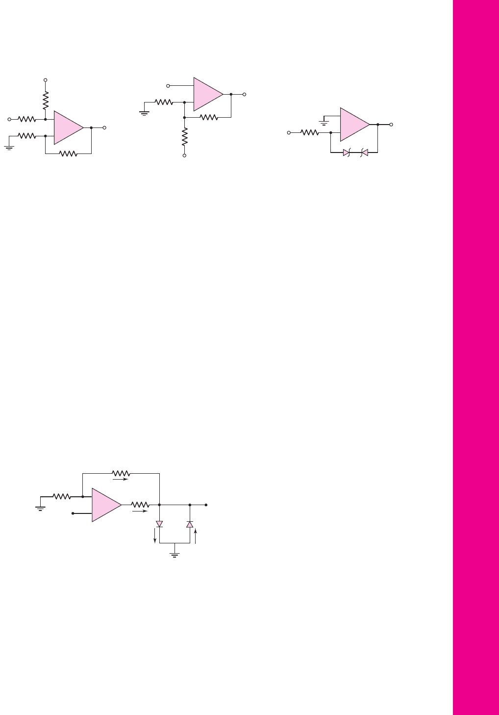
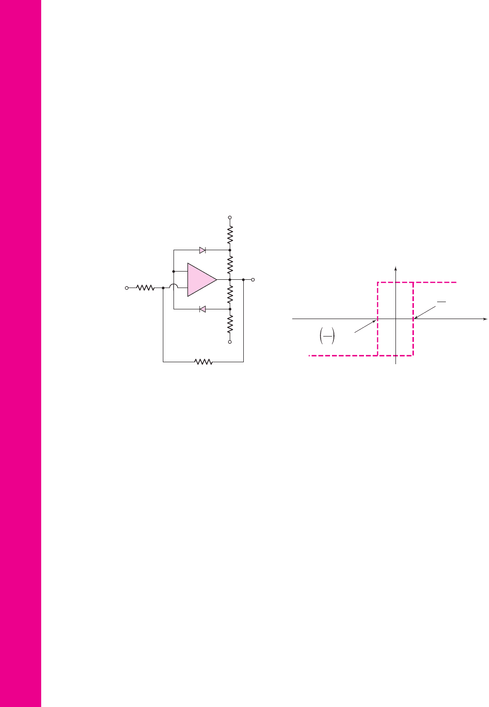
15.55 (a) For the Schmitt trigger with limiter in Figure P15.55(a), find the two
output voltage values at
v
I
= 0
and the two crossover voltages. (b) Derive
the expression for the slope of
v
O
versus
v
I
for
v
I
> V
TH
.
Section 15.4 Nonsinusoidal Oscillators and Timing Circuits
15.56 Consider the Schmitt trigger oscillator in Figure 15.35. The circuit parame-
ters are
R
1
= 10
k
,
R
2
= 20
k
,
R
X
= 40
k
, and
C
X
= 0.02 μF
. The
saturated output voltages are
±5
V. (a) Write the expressions for
v
X
as a
function of time assuming that
v
O
has switched to its high state at
t = 0
.
(b) Determine the frequency of oscillation and the duty cycle.
15.57 Repeat Problem 15.56 for saturated output voltages of
V
H
=+5
V and
V
L
=−10
V.
D15.58 Design the Schmitt trigger circuit in Figure 15.35 to produce a square-wave
output signal at a frequency of
f
o
= 12 kHz
and a 50 percent duty cycle.
Choose standard component values.
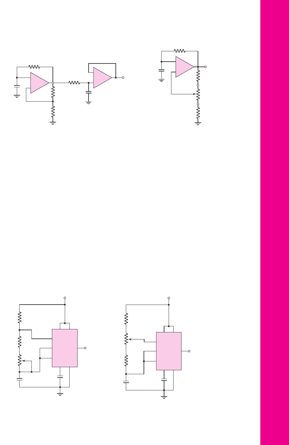
15.59 Consider the circuit in Figure P15.59. The saturated output voltages of the
Schmitt trigger comparator are
±10
V. Assume that at
t = 0
, output
v
o1
switches from its low state to its high state and
C
Y
is uncharged. Plot
v
o1
and
v
o
versus time over two periods of oscillation.
15.60 The saturated output voltages of the comparator in Figure P15.60 are
±10
V. (a) Find
R
x
such that the frequency of oscillation is 500 Hz when the
potentiometer is connected to point A. (b) Using the results of part (a),
determine the oscillator frequency when the potentiometer is connected to
point B.
(a)
–V
REF
V
REF
1 kΩ
R
2
R
1
v
I
1 kΩ
1 kΩ
1 kΩ
–
+
v
O
v
O
v
I
+(V
REF
+ 2V
g
)
V
TH
=(V
REF
+ 2V
g
)
R
1
R
2
– (V
REF
+ 2V
g
)
V
TH
= – (V
REF
+ 2V
g
)
R
1
R
2
(b)
nea80644_ch15_1061-1140.qxd 07/12/2009 3:59 Page 1134 pinnacle MHDQ-New:MHDQ134:MHDQ134-15:
Chapter 15 Applications and Design of Integrated Circuits 1135
84
5
6
23
7
1
V
+
= 10 V
R
1
=
10 kΩ
R
2
=
10 kΩ
R
3
=
100 kΩ
C =
0.01 mF
0.01 mF
v
O
Figure P15.66
84
5
6
23
7
1
V
+
= 10 V
R
1
=
1 kΩ
R
3
=
50 kΩ
R
2
=
1 kΩ
C =
0.01 mF
0.01 mF
v
O
Figure P15.67
15.61 (a) The monostable multivibrator in Figure 15.37 is to be designed to pro-
duce a
250 μ
s output pulse. Assume saturated output voltages of
±10
V, and
let
V
γ
= 0.7
V,
R
1
= 20
k
, and
R
2
= 12
k
. (b) Determine the minimum
input triggering voltage required. (c) What is the recovery time?
15.62 A monostable multivibrator is shown in Figure 15.37. The parameters are
R
X
= 20
k
,
C
X
= 1.2 μ
F, and
R
1
= R
2
= 20
k
. The saturated output
voltages are
±5
V. (a) What is the output voltage pulse width? (b) Deter-
mine the recovery time.
D15.63 Figure 15.40 shows the 555 timer connected in the monostable multivibra-
tor mode. (a) Design the circuit to provide an output pulse 60 seconds wide.
(b) Determine the recovery time.
D15.64 Design a 555 monostable multivibrator to provide a 5
μ
s pulse. What is the
recovery time?
15.65 A 555 timer is connected in the astable mode as shown in Figure 15.41.
Design the circuit such that the frequency of oscillation is
f
o
= 80
kHz and
the duty cycle is 60 percent. Let
R
A
= 25
k
.
15.66 A 555 ICC is connected as shown in Figure P15.66. Determine the range of
oscillation frequency and the duty cycle.
15.67 Repeat Problem 15.66 for the circuit in Figure P15.67.
C
X
=
0.1 mF
C
Y
= 0.02 mF
R
X
= 10 kΩ
R
2
= 10 kΩ
R
1
= 10 kΩ
R
Y
= 2 kΩ
v
O1
v
O
–
+
–
+
Figure P15.59
C
X
=
0.01 mF
R
X
R
2
= 10 kΩ
R
3
= 10 kΩ
R
1
= 10 kΩ
v
O
A
B
–
+
Figure P15.60
nea80644_ch15_1061-1140.qxd 07/12/2009 3:59 Page 1135 pinnacle MHDQ-New:MHDQ134:MHDQ134-15:

1136 Part 2 Analog Electronics
Section 15.5 Integrated Circuit Power Amplifiers
15.68 The LM380 power amplifier in Figure 15.42 is biased at
V
+
= 22 V
. Let
β
n
= 100
and
β
p
= 20
for the npn and pnp transistors, respectively. (a) De-
termine the quiescent collector currents in transistors
Q
1
through
Q
6
.
(b) Assume that diodes
D
1
and
D
2
and transistors
Q
7
,
Q
8
, and
Q
9
are all
matched, with parameters
I
S
= 10
−13
A. For zero input voltages, determine
the quiescent currents in
D
1
,
D
2
,
Q
7
,
Q
8
, and
Q
9
. (c) For no load, calculate
the quiescent power dissipated in the amplifier.
15.69 An LM380 must deliver ac power to a 10
load. The maximum power dis-
sipated in the amplifier must be limited to 2 W and the maximum allowed
distortion must be limited to 3 percent. Determine: (a) the maximum power
that can be delivered to the load, (b) the maximum supply voltage, and
(c) the peak amplitude of the sinusoidal output voltage.
15.70 (a) Design the bridge circuit in Figure 15.46 such that the gain magnitude of
each op-amp circuit is 12. (b) A load resistance of
R
L
= 12
that is to dis-
sipate an average power of
P
L
= 15
W is connected to the output. Deter-
mine the peak output voltage at each op-amp and the peak current that each
op-amp must source or sink. (c) If the peak output voltage of each op-amp
is limited to
±12
V and the peak current that each op-amp can source or
sink is limited to 0.8 A, determine (i) the maximum average power that can
be delivered to the load and (ii) the optimum value of load resistance.
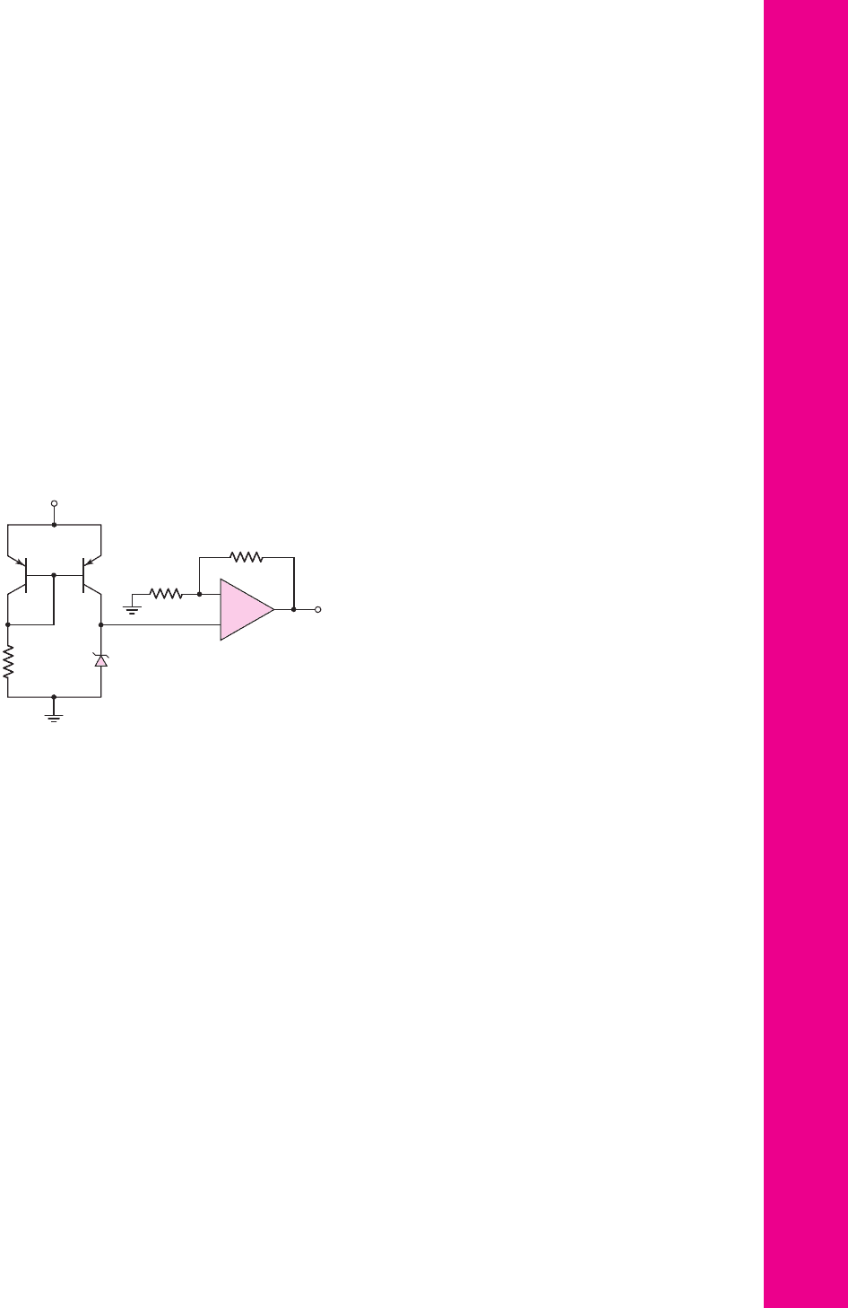
D15.71 Another form of the bridge power amplifier is shown in Figure P15.71. This
amplifier has a very high input resistance since the input is to the noninvert-
ing terminal of an op-amp. (a) Derive the expression for the voltage gain
A
v
= v
L
/v
I
. (b) Design the circuit to provide a gain of
A
v
= 10
so that the
magnitudes of
v
o1
and
v
o2
are equal. Let
R
1
= 50 k
. (c) If
R
L
= 20
and
if the average power delivered to the load is 10 W, determine the peak am-
plitude of
v
o1
and
v
o2
and the peak load current.
v
L
v
I
v
O1
v
O2
+
–
R
L
R
2
R
3
R
1
A
1
A
2
–
+
+
–
Figure P15.71
–
+
–
+
+
–
R
L
R
4
R
3
R
2
R
1
A
1
A
2
v
L
v
I
v
O2
v
O1
Figure P15.72
15.72 Figure P15.72 shows an audio amplifier using two identical op-amps con-
nected in a bridge configuration. (a) Derive the expression for the voltage
gain
A
v
= v
L
/v
I
. (b) Design the system such that
|
v
O1
|
=
|
v
O2
|
= 12v
I
.
The largest resistor value is to be limited to 120 k
. (c) If
R
L
= 25
and
the peak op-amp output voltages are limited to
±8
V, determine (i) the max-
imum average power that can be delivered to the load and (ii) the peak cur-
rents that each op-amp must source or sink.
nea80644_ch15_1061-1140.qxd 07/12/2009 3:59 Page 1136 pinnacle MHDQ-New:MHDQ134:MHDQ134-15:
Chapter 15 Applications and Design of Integrated Circuits 1137
D15.73 (a) Design the circuit shown in Figure P15.72 such that
v
O1
=−v
O2
and the
voltage gain
A
v
= v
L
/v
I
= 25
. The largest resistor value is to be limited to
100 k
. (b) If the peak value of each op-amp output voltage is limited to
±12
V and the peak current that each op-amp can source or sink is limited
to 1.2 A, determine (i) the maximum average power that can be delivered to
the load and (ii) the optimum load resistance. (c) If
R
L
is twice the value
found in part (b), what is the maximum average power that can be delivered
to the load?
Section 15.6 Voltage Regulators
15.74 Transistors
Q
1
and
Q
2
in the voltage regulator circuit in Figure P15.74 have
parameters
β = 200
,
V
EB
(on) = 0.7V
, and
V
A
= 100 V
. The zero-current
Zener voltage is
V
ZO
= 6.3V
and the Zener resistance is
r
z
= 15
.
Assuming an ideal op-amp, calculate the line regulation.
V
+
= 10 V
10 kΩ
90 kΩ
V
O
Q
2
Q
1
R
1
=
9.3 kΩ
V
Z
+
–
–
+
Figure P15.74
15.75 (a) The output voltage of a voltage regulator decreases by 8 mV as the load
current changes from 0 to 2 A. If the output voltage changes linearly with
load current, determine the output resistance of the regulator. (b) If the out-
put resistance of a voltage regulator is
R
of
= 10
m
and the output current
changes by 1.2 A, what is the change in output voltage?
15.76 Consider the three-terminal voltage regulator in Figure 15.51, with para-
meters as given in Example 15.16. If the maximum load current is
I
O
(max) = 100 mA
, determine the minimum applied power supply voltage
V
+
that will still maintain all transistors biased in the active region.
D15.77 Consider the three-terminal voltage regulator in Figure 15.51, with Zener
diode voltages of
V
Z
= 6.3V
. Assume transistor parameters of
V
BE
(npn) =
V
EB
(pnp) =0.6V
, and neglect base currents. (a) Determine resistance
R
4
such that
I
Z2
= 0.25 mA
. (b) Determine
R
12
such that
V
O
= 12 V
.
15.78 The three-terminal voltage regulator in Figure 15.51 has parameters as
described in Example 15.16. Assume
R
4
= 0
,
V
A
= 50 V
for
Q
4
, and
r
z
= 15
for
D
2
. Determine the line regulation.
15.79 The voltage regulator shown in Figure P15.79 is a variable voltage, 0 to 5 A
power supply. The transistor parameters are
β = 80
and
V
BE
(
on
)
= 0.7
V.
The op-amp has a finite open-loop gain of
A
OL
= 5 ×10
3
. The zero-current
nea80644_ch15_1061-1140.qxd 07/12/2009 3:59 Page 1137 pinnacle MHDQ-New:MHDQ134:MHDQ134-15: