Neamen D. Microelectronics: Circuit Analysis and Design
Подождите немного. Документ загружается.

1138 Part 2 Analog Electronics
Zener voltage is
V
ZO
= 5.6
V and the Zener resistance is
r
z
= 12
. (a) For
I
Z
= 12
mA, find
R
1
. (b) Determine the range of output voltage as the po-
tentiometer
R
3
is varied. (c) If the potentiometer is set such
x = 1
, deter-
mine the load regulation. Assume
R
o
of the op-amp is zero.
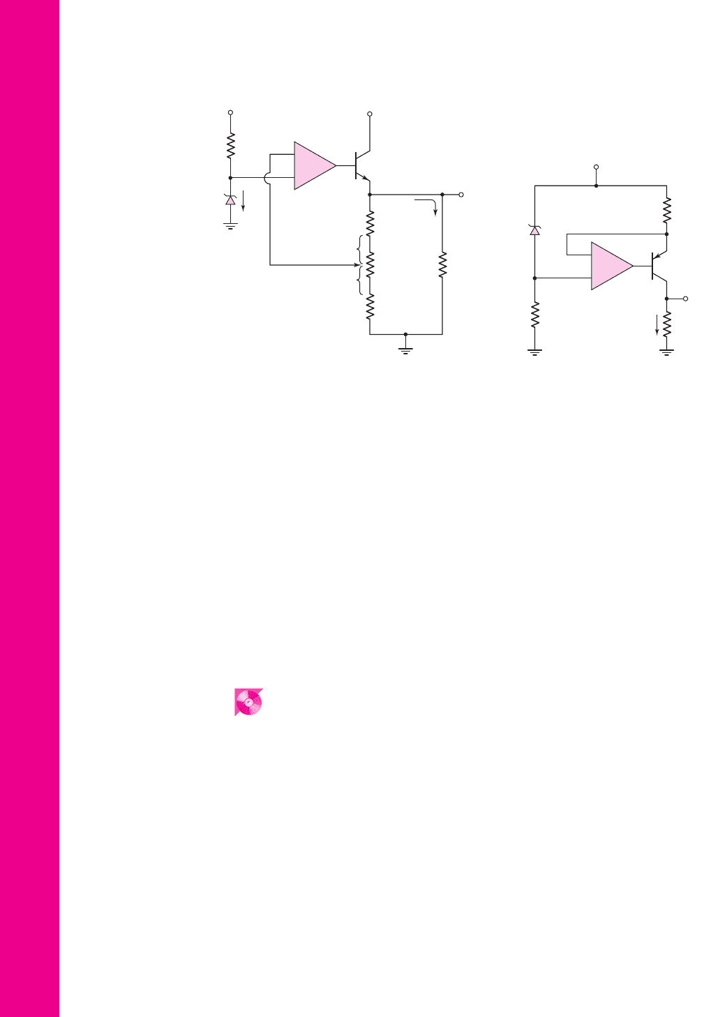
15.80 The parameters of the transistor in Figure P15.80 are
β = 80
and
V
EB
(
on
)
= 0.6
V. The Zener diode is ideal with
V
Z
= 6.8
V and the op-amp
is ideal. (a) Determine the range of load resistance
R
L
such that the load
current is a constant. What is the value of the constant load current? (b) If
the Zener diode has a resistance
r
z
= 20
and the power supply is in the
range
16 ≤ V
+
≤ 20
V, determine the range in output current for
R
L
= 5
k
.
COMPUTER SIMULATION PROBLEMS
15.81 Consider the three-pole high-pass Butterworth active filter described in
Exercise TYU 15.1. Using a computer simulation, plot the magnitude of the
voltage transfer function versus frequency and compare these results with
those obtained in TYU 15.1.
15.82 A phase shift oscillator is described in Exercise TYU 15.5. Using a com-
puter simulation, plot the output voltage of the oscillator versus time over
several cycles. What is the frequency of oscillation?
15.83 Consider the Schmitt trigger oscillator described in Exercise Ex 15.8. Using
a computer simulation, plot the voltage
v
X
versus time over several cycles.
What is the frequency of oscillation?
15.84 A bridge power amplifier is described in Exercise TYU 15.13. Using a com-
puter simulation, plot (a)
v
O1
−v
O2
versus
v
I
over the range
0 ≤ v
I
≤ 4
V
and (b) the current in
R
L
over the same input voltage range.
V
O
R
4
= 1 kΩ
R
2
= 1 kΩ
R
3
= 2 kΩ
R
L
+
–
V
Z
I
Z
R
1
V
+
= 25 V
V
+
= 25 V
Q
I
O
x
(1 – x)
–
+
Figure P15.79
V
O
R
2
= 5 kΩ
R
1
= 10 kΩ
D
1
R
L
+
–
V
Z
V
+
= 20
I
O
Q
–
+
Figure P15.80
nea80644_ch15_1061-1140.qxd 07/12/2009 3:59 Page 1138 pinnacle MHDQ-New:MHDQ134:MHDQ134-15:
DESIGN PROBLEMS
[Note: Each design should be correlated with a computer analysis.]
D15.85 Design a four-pole high-pass Butterworth active filter such that the low-
frequency voltage gain is +20 and the cutoff frequency is 50 Hz.
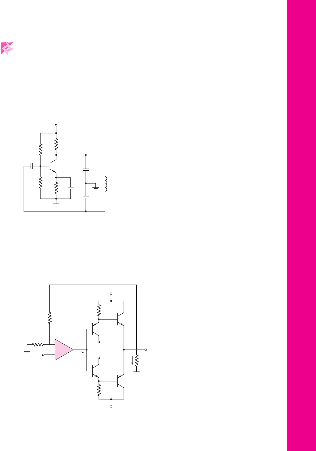
D15.86 Consider the Colpitts oscillator in Figure P15.86. The capacitors
C
E
and
C
B
are very large bypass and coupling capacitors. Let
V
CC
= 5
V. (a) Design
the circuit such that the quiescent collector current is
I
CQ
= 0.5
mA.
(b) Design the circuit such that the frequency of oscillation is
f
o
= 650
kHz.
*
*
Chapter 15 Applications and Design of Integrated Circuits 1139
i
I
R
B
R
A
R
1
R
2
v
I
v
O
i
L
R
L
Q
1
Q
2
Q
4
Q
3
V
+
V
–
V
+
V
–
–
+
Figure P15.87
+V
CC
R
C
R
E
C
B
C
E
R
1
R
2
C
2
C
1
L
Figure P15.86
D15.87 Consider the power amplifier in Figure P15.87 with parameters
V
+
= 15 V
,
V
−
=−15
V, and
R
L
= 20
. The closed-loop gain must be
10. Design the circuit such that the power delivered to the load is 5 W when
v
I
=−1
V. If the four transistors are matched, determine the minimum
β
required such that the op-amp output current is limited to 2 mA when 5 W
is delivered to the load.
*
nea80644_ch15_1061-1140.qxd 07/12/2009 3:59 Page 1139 pinnacle MHDQ-New:MHDQ134:MHDQ134-15:

D15.88 Consider the simple series-pass regulator circuit in Figure P15.88. Assume
an ideal Zener diode with
V
Z
= V
REF
= 4.7V
. Let
β = 100
and
V
BE
(on) = 0.7V
for all transistors. (a) Design the circuit such that
V
O
= 10 V
and
I
Z
= 10 mA
for a nominal supply voltage of
V
+
= 20 V
.
(b) Determine the regulator output resistance
R
of
.
*
1140 Part 2 Analog Electronics
R
3
R
o
Q
1
Q
2
Q
3
I
Z
I
O
R
2
R
L
V
O
V
+
R
1
R
4
+
–
V
REF
Figure P15.88
nea80644_ch15_1061-1140.qxd 07/12/2009 3:59 Page 1140 pinnacle MHDQ-New:MHDQ134:MHDQ134-15:

Prologue
III
III
Prologue to Digital
Electronics
PREVIEW
Several basic digital electronics concepts are common to the remaining chapters of
this text. These principles, which are usually covered in an introductory course in
computer logic design, are reviewed briefly in this prologue.
In a digital system, information is represented solely in discrete or quantized
form. Normally, only two discrete states are used, denoted as logic 0 and logic 1. The
algebra applicable to the binary system was invented by George Boole (1815–1864)
and is known as Boolean algebra. We do not use Boolean algebra directly in this text;
however, some familiarity with it is beneficial in the analysis and design of digital in-
tegrated circuits. We will be directly concerned with basic Boolean operations and
the corresponding logic gates.
Several techniques have been developed to aid in the reduction of Boolean ex-
pressions to a minimum set of variables. One common technique is the Karnaugh
map. Though not used directly in this text, this technique is helpful in designing dig-
ital systems.
LOGIC FUNCTIONS AND LOGIC GATES
The three basic logic or Boolean operations are: NOT, AND, and OR. These opera-
tions can be described using a truth table.
The truth table and logic gate symbol for the NOT function is shown in
Figure PR3.1(a). The bar over the output variable indicates the NOT function, or the
complement. Since only two states of a variable are permitted, if
A = 0
, then
¯
A = 1
.
The small circle at the output of the logic gate indicates a logic inversion. As depicted
by the figure, this logic gate is also called an inverter.
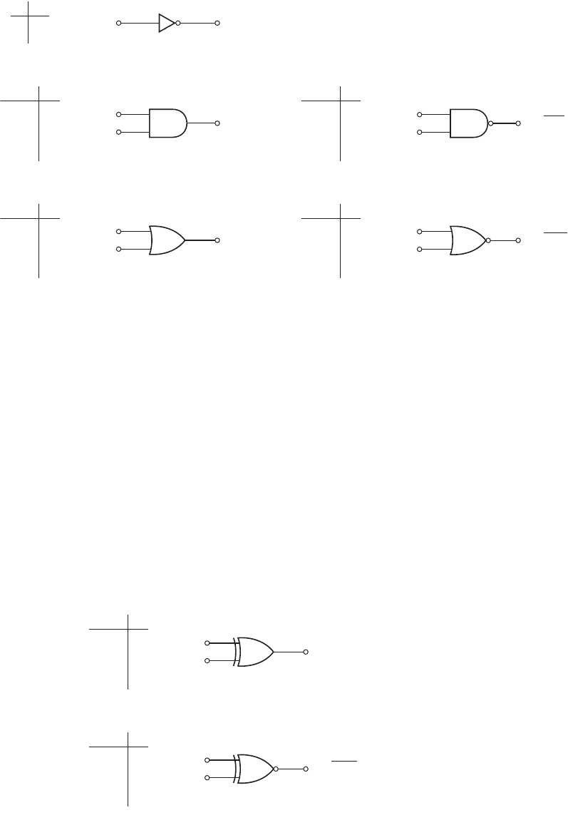
Figure PR3.1(b) shows the truth table, logic gate symbol, and Boolean expres-
sion for the AND function. A logic 1 is produced at the output only when both inputs
are a logic 1; otherwise, the output is a logic 0.
The truth table, logic gate symbol, and Boolean expression for the OR operation
are shown in Figure PR3.1 (c). In this case, a logic 1 output is produced if either
A = 1
or
B = 1
, or if both inputs are a logic 1.
Two other commonly used logic functions are the NAND and NOR. The NAND
function is the complement of the AND operation, and the NOR function is the com-
plement of the OR operation. The truth tables and logic gate symbols for these func-
tions are shown in Figure PR3.2. Again, the small circle at the output of each logic
gate indicates a logic inversion.
Finally, two additional logic functions useful in digital design are the exclu-
sive-OR function and the exclusive-NOR function. Although these logic functions
can be derived from a combination of the basic functions, they have their own logic
1141
nea80644_pro03_1141-1144.qxd 07/15/2009 09:52 PM Page 1141 F506 Hard disk:Desktop Folder:ALI-07-15-09:
1142 Prologue III Prologue to Digital Electronics
gate symbols. The truth tables, logic gate symbols, and Boolean expressions for
these operations are shown in Figure PR3.3. In the exclusive-OR operation, the
output becomes a logic 1 when either
A = 1
or
B = 1
, but not when both are a
logic 1. The output of the exclusive-NOR is the complement of the exclusive-OR
function.
In the following sections of this prologue, we briefly describe the basic logic
functions and logic gates with two input variables, although more than two are
possible. In practice, the number of input variables is generally limited to a maxi-
mum of four because of transistor size and input capacitance effects.
A
B
Q = A
⋅
B
A
B
Q = A + B
BAQ
0
1
0
1
0
0
1
1
1
1
1
0
BAQ
0
1
0
1
0
0
1
1
1
0
0
0
(a)
(b)
Figure PR3.2 Truth tables, logic gate symbols,
and Boolean expressions: (a) NAND function and
(b) NOR function
Q = A ⊗ B
A
B
Q = A ⊗ B
BAQ
0
1
0
1
0
0
1
1
0
1
1
0
BAQ
0
1
0
1
0
0
1
1
1
0
0
1
(a)
(b)
A
B
Figure PR3.3 Truth tables, logic gate symbols, and Boolean expressions: (a) exclusive-OR
function and (b) exclusive-NOR function
A
A
B
AQ
Q = A
–
Q = A
⋅
B
A
B
Q = A + B
0
1
1
0
BAQ
0
1
0
1
0
0
1
1
0
0
0
1
BAQ
0
1
0
1
0
0
1
1
0
1
1
1
(a)
(b)
(c)
Figure PR3.1 Truth tables, logic gate symbols,
and Boolean expressions: (a) NOT function,
(b) AND function, and (c) OR function
nea80644_pro03_1141-1144.qxd 07/12/2009 2:50 Page 1142 pinnacle MHDQ-New:MHDQ134:MHDQ134-PROL-PRIII:
LOGIC LEVELS
The logic 0 and logic 1 states in a digital circuit are represented by two distinct volt-
age values. In this text, we use positive logic, which means that the more positive
voltage represents the logic 1 state and the more negative voltage represents the
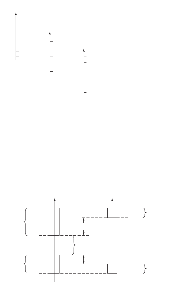
logic 0 state. The actual voltages may be either positive or negative. Figure PR3.4
shows three possible output voltage combinations that represent positive logic. The
condition represented in Figure PR3.4(a) is the most common, although we will see
examples of the conditions represented in Figure PR3.4(c). The logic 0 level shown
in Figure PR3.4(a) may actually be zero volts in some cases.
Prologue III Prologue to Digital Electronics 1143
Logic 1
Logic 0
0
Output
voltage
Logic 1
Logic 0
0
Output
voltage
Logic 1
Logic 0
0
Output
voltage
(a) (b)
(c)
Figure PR3.4 Three possible output voltage combinations representing positive logic
NOISE MARGIN
In an ideal digital system, logic 1 would be represented by a well-defined voltage
level
V
OH
and logic 0 would be represented by a well-defined voltage level
V
OL
. In
actual digital systems, however, the voltage values representing the two logic states
may change as a result of any number of factors, including variations in temperature,
circuit fabrication tolerances, loading effects, and noise.
At the input to a digital circuit, a range of voltages can represent each of the two
binary states as illustrated in Figure PR3.5. The amplitude levels that pass through a
Logic 1
input range
Logic 1
output range
Logic 0
output range
Undefined
range
Input Output
Logic 0
input range
V
OH
V
IL
V
OL
V
OHU
NM
H
NM
L
V
OLU
V
IH
Figure PR3.5 Voltage ranges representing logic 1 and logic 0, and definition of noise margins
nea80644_pro03_1141-1144.qxd 07/12/2009 2:50 Page 1143 pinnacle MHDQ-New:MHDQ134:MHDQ134-PROL-PRIII:
digital system must be regenerated in order that a logic error is not produced. Voltage
V
IH
is the smallest input voltage recognized as a logic 1 and
V
IL
is the largest input
voltage recognized as a logic 0. These input levels produce output voltages in the
ranges shown in Figure PR3.5. In an inverter circuit, input
V
IL
produces output
V
OHU
and input
V
IH
produces output
V
OLU
. The noise margins, then, are defined as
shown in the figure. We consider noise margins in more detail in the next two chap-
ters when we analyze specific circuits.
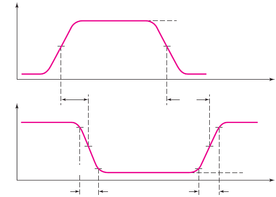
PROPAGATION DELAY TIMES
AND SWITCHING TIMES
The switching characteristics of logic gates are generally described by propagation
delay times. Standard definitions of digital circuit delay times are illustrated in Fig-
ure PR3.6. Propagation delay times from input to output, denoted
τ
PHL
and
τ
PLH
,are
defined between the 50 percent points of the input and output pulse waveforms.
In addition, high-to-low and low-to-high transition times at the output of a logic
gate are defined as the times between the 10 and 90 percent points and are denoted
τ
HL
and
τ
LH
.
1144 Prologue III Prologue to Digital Electronics
V
OH
V
in
V
out
V
OL
V
OH
V
OL
t
LH
t
HL
t
PHL
t
PLH
50%
90%
50%
10%
Figure PR3.6 Standard definitions of digital delay times and propagation delay times
SUMMARY
These concepts, all of which should be familiar to the reader from a computer logic
design course, are applied to specific digital logic circuits in the following two chap-
ters of the text.
nea80644_pro03_1141-1144.qxd 07/12/2009 2:50 Page 1144 pinnacle MHDQ-New:MHDQ134:MHDQ134-PROL-PRIII:

PART
Digital
Electronics
3
3
Part 2 of the text dealt with analog electronic circuits. Part 3 now deals with digital
electronics, another important category of electronics.
Chapter 16 examines field-effect transistor digital circuits. MOSFET digital cir-
cuits have revolutionized digital electronics, with CMOS technology producing
high-density, low-power digital circuits. Initially, we briefly consider the NMOS
inverter and NMOS logic gates. We then analyze the basic CMOS inverter and then
develop CMOS logic gates. Finally, we analyze FET shift registers and flip-flops and
then discuss some basic A/D and D/A converters.
Bipolar digital circuits are considered in Chapter 17. We initially examine
emitter-coupled logic, which is primarily used in specialized high-speed applica-
tions. We then briefly consider the basic aspects of transistor-transistor logic (TTL),
which was the mainstay of logic design for many years. Low-power Schottky TTL
circuits are analyzed in order to obtain a good comparison between FET and bipolar
digital technologies.
1145
nea80644_ch16_1145-1254.qxd 07/12/2009 3:37 Page 1145 pinnacle MHDQ-New:MHDQ134:MHDQ134-16:
nea80644_ch16_1145-1254.qxd 07/12/2009 3:37 Page 1146 pinnacle MHDQ-New:MHDQ134:MHDQ134-16:

Chapter
MOSFET Digital Circuits
16
16
This chapter presents the basic concepts of MOSFET digital integrated circuits,
which is the most widely used technology for the fabrication of digital systems. The
small transistor size and low power dissipation of CMOS circuits allows for a high
level of integration for logic and memory circuits. JFET logic circuits are very spe-
cialized and are therefore not considered here.
A discussion of NMOS logic circuits will serve as an introduction to the analy-
sis and design of digital systems. This technology, although old, deals with only one
type of transistor (n-channel) and therefore makes the analysis more straightforward
than dealing with two types of transistors in the same circuit. This discussion will
also serve as a baseline to point out advantages of CMOS technology.
Initially, we consider basic digital logic circuits such as NOR and NAND gates,
and then discuss additional logic circuits such as flip flops, shift registers, and adders.
Finally, we consider memories, and then A/D and D/A converters.
PREVIEW
In this chapter, we will:
• Analyze and design NMOS inverters
• Analyze and design NMOS logic gates
• Analyze and design CMOS inverters
• Analyze and design static CMOS logic gates
• Analyze and design clocked CMOS logic gates
• Analyze and understand the characteristics of NMOS and CMOS transmis-
sion gates
• Analyze and understand the characteristics of shift registers and various flip-
flop designs
• Discuss semiconductor memories
• Analyze and design random-access memory (RAM) cells
• Analyze read-only memories (ROM)
• Discuss the basic concepts in A/D and D/A converters
• As an application, design a static CMOS logic gate to implement a specific
logic function.
1147
nea80644_ch16_1145-1254.qxd 07/12/2009 3:37 Page 1147 pinnacle MHDQ-New:MHDQ134:MHDQ134-16: