Neamen D. Microelectronics: Circuit Analysis and Design
Подождите немного. Документ загружается.

88 Part 1 Semiconductor Devices and Basic Applications
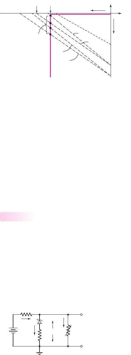
Figure 2.18 shows the Zener diode I–V characteristics. Superimposed on the figure
are the four load lines designated as A, B, C, and D. Each load line intersects the
diode characteristics in the breakdown region, which is the required condition for
proper diode operation. The variation in Zener diode current
I
Z
for the various
combinations of input voltage and load resistance is shown on the figure.
If we were to choose the input resistance to be
R
i
= 25
and let
v
PS
= 11
V
and
R
L
= 90
, the load line equation (Equation (2.32)) becomes
V
Z
= 8.61 − I
Z
(19.6)
(2.33)
This load line is plotted as curve E on Figure 2.18. We see that this load line does not
intersect the diode characteristics in the breakdown region. For this condition, the
output voltage will not equal the breakdown voltage of
V
Z
= 9
V; the circuit does not
operate “properly.”
Zener Resistance and Percent Regulation
In the ideal Zener diode, the Zener resistance is zero. In actual Zener diodes, how-
ever, this is not the case. The result is that the output voltage will fluctuate slightly
with a fluctuation in the input voltage, and will fluctuate with changes in the output
load resistance.
Figure 2.19 shows the equivalent circuit of the voltage regulator including the
Zener resistance. Because of the Zener resistance, the output voltage will change
with a change in the Zener diode current.
Two figures of merit can be defined for a voltage regulator. The first is the source
regulation and is a measure of the change in output voltage with a change in source
2.2.2
13.6 11.7
0.73
0.907
9.43
D
C
B
A
E
9
11.0
V
Z
(V)
ΔI
Z
I
Z
(mA)
Figure 2.18 Zener diode I–V characteristics with various load lines superimposed
+
–
V
L
+
–
V
PS
R
L
R
i
I
I
I
L
I
Z
r
z
+
–
V
Z
Figure 2.19 A Zener diode voltage regulator circuit with a nonzero Zener resistance
nea80644_ch02_067-124.qxd 06/08/2009 07:28 PM Page 88 F506 Tempwork:Dont' Del Rakesh:June:Rakesh 06-08-09:MHDQ134-02 Folder:M

Chapter 2 Diode Circuits 89
voltage. The second is the load regulation and is a measure of the change in output
voltage with a change in load current.
The source regulation is defined as
Source regulation =
v
L
v
PS
×100%
(2.34)
where
v
L
is the change in output voltage with a change of
v
PS
in the input
voltage.
The load regulation is defined as
Load regulation =
v
L,no load
−v
L,full load
v
L,full load
×100%
(2.35)
where
v
L,no load
is the output voltage for zero load current and
v
L,full load
is the output
voltage for the maximum rated output current.
The circuit approaches that of an ideal voltage regulator as the source and load
regulation factors approach zero.
EXAMPLE 2.6
Objective: Determine the source regulation and load regulation of a voltage regula-
tor circuit.
Consider the circuit described in Example 2.5 and assume a Zener resistance of
r
z
= 2
.
Solution: Consider the effect of a change in input voltage for a no-load condition
(
R
L
=∞
). For
v
PS
= 13.6V
, we find
I
Z
=
13.6 − 9
15.3 + 2
= 0.2659 A
Then
v
L,max
= 9 +(2)(0.2659) = 9.532 V
For
v
PS
= 11
V, we find
I
Z
=
11 − 9
15.3 + 2
= 0.1156 A
Then
v
L,min
= 9 +(2)(0.1156) = 9.231 V
We obtain
Source regulation =
v
L
v
PS
×100% =
9.532 − 9.231
13.6 − 11
×100% = 11.6%
Now consider the effect of a change in load current for
v
PS
= 13.6V
. For
I
L
= 0
,we
find
I
Z
=
13.6 − 9
15.3 + 2
= 0.2659 A
and
v
L,no load
= 9 +(2)(0.2659) = 9.532 V
nea80644_ch02_067-124.qxd 06/08/2009 07:28 PM Page 89 F506 Tempwork:Dont' Del Rakesh:June:Rakesh 06-08-09:MHDQ134-02 Folder:M

90 Part 1 Semiconductor Devices and Basic Applications
For a load current of
I
L
= 100
mA, we find
I
Z
=
13.6 − [9 + I
Z
(2)]
15.3
−0.10
which yields
I
Z
= 0.1775 A
Then
v
L,full load
= 9 +(2)(0.1775) = 9.355 V
We now obtain
Load regulation =
v
L,no load
−v
L,full load
v
L,full load
×100%
=
9.532 − 9.355
9.355
×100% = 1.89%
Comment: The ripple voltage on the input of 2.6 V is reduced by approximately a
factor of 10. The change in output load results in a small percentage change in the
output voltage.
EXERCISE PROBLEM
Ex 2.6: Repeat Example 2.6 for
r
z
= 4
. Assume all other parameters are the same
as listed in the example. (Ans. Source regulation =20.7%, load regulation =3.29%)
Test Your Understanding
TYU 2.5 Consider the circuit shown in Figure 2.19. Let
V
PS
= 12
V,
V
ZO
= 6.2
V,
and
r
z
= 3
. The power rating of the diode is
P = 1
W. (a) Determine
I
Z
(max)
and
R
i
. (b) If
I
Z
(min) = 0.1I
Z
(max)
, determine
R
L
(min)
and the load regulation. (Ans.
(a)
I
Z
(max) = 150
mA,
R
i
= 35.7
; (b)
R
L
(min) = 42.7 , 6.09 %)
.
TYU 2.6 Suppose the current-limiting resistor in Example 2.5 is replaced by one
whose value is
R
i
= 20
. Determine the minimum and maximum Zener diode cur-
rent. Does the circuit operate “properly”? (Ans.
I
Z
(min) = 0
,
I
Z
(max) = 230
mA).
TYU 2.7 Suppose the power supply voltage in the circuit shown in Figure 2.17 drops
to
V
PS
= 10 V
. Let
R
i
= 15.3
. What is the maximum load current in the radio if
the minimum Zener diode current is to be maintained at
I
Z
(min) = 30
mA? (Ans.
I
L
(max) = 35.4
mA).
2.3 CLIPPER AND CLAMPER CIRCUITS
Objective: • Apply the nonlinear characteristics of diodes to create
waveshaping circuits known as clippers and clampers.
In this section, we continue our discussion of nonlinear circuit applications of diodes.
Diodes can be used in waveshaping circuits that either limit or “clip” portions of a
signal, or shift the dc voltage level. The circuits are called clippers and clampers,
respectively.
nea80644_ch02_067-124.qxd 06/08/2009 07:28 PM Page 90 F506 Tempwork:Dont' Del Rakesh:June:Rakesh 06-08-09:MHDQ134-02 Folder:M
Chapter 2 Diode Circuits 91
Clippers
Clipper circuits, also called limiter circuits, are used to eliminate portions of a sig-
nal that are above or below a specified level. For example, the half-wave rectifier is a
clipper circuit, since all voltages below zero are eliminated. A simple application of
a clipper is to limit the voltage at the input to an electronic circuit so as to prevent
breakdown of the transistors in the circuit. The circuit may be used to measure the
frequency of the signal, if the amplitude is not an important part of the signal.
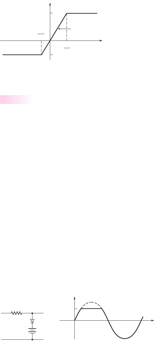
Figure 2.20 shows the general voltage transfer characteristics of a limiter circuit.
The limiter is a linear circuit if the input signal is in the range
V
−
O
/A
v
≤ v
I
≤
V
+
O
/A
v
, where
A
v
is the slope of the transfer curve. If
A
v
≤ 1
, as in diode circuits,
the circuit is a passive limiter. If
v
I
> V
+
O
/A
v
, the output is limited to a maximum
value of
V
+
O
. Similarly, if
v
I
< V
−
O
/A
v
, the output is limited to a minimum value of
V
−
O
. Figure 2.20 shows the general transfer curve of a double limiter, in which both
the positive and negative peak values of the input signal are clipped.
Various combinations of
V
+
O
and
V
−
O
are possible. Both parameters may be pos-
itive, both negative, or one may be positive while the other negative, as indicated in
the figure. If either
V
−
O
approaches minus infinity or
V
+
O
approaches plus infinity,
then the circuit reverts to a single limiter.
Figure 2.21(a) is a single-diode clipper circuit. The diode D
1
is off as long as
v
I
< V
B
+ V
γ
. With D
1
off, the current is approximately zero, the voltage drop
across R is essentially zero, and the output voltage follows the input voltage. When
v
I
> V
B
+ V
γ
, the diode turns on, the output voltage is clipped, and
v
O
equals
V
B
+ V
γ
. The output signal is shown in Figure 2.21(b). In this circuit, the output is
clipped above
V
B
+ V
γ
.
2.3.1
v
O
v
I
V
O
+
V
O
–
V
O
–
A
v
V
O
+
A
v
Slope = A
v
Figure 2.20 General voltage transfer characteristics of a limiter circuit
v
t
v
O
v
I
V
B
+ V
g
(a) (b)
+
+
–
–
v
I
V
B
D
1
R
+
–
v
o
Figure 2.21 Single-diode clipper: (a) circuit and (b) output response
nea80644_ch02_067-124.qxd 06/08/2009 07:28 PM Page 91 F506 Tempwork:Dont' Del Rakesh:June:Rakesh 06-08-09:MHDQ134-02 Folder:M
92 Part 1 Semiconductor Devices and Basic Applications
The resistor R in Figure 2.21 is selected to be large enough so that the forward
diode current is limited to be within reasonable values (usually in the milliampere
range), but small enough so that the reverse diode current produces a negligible volt-
age drop. Normally, a wide range of resistor values will result in satisfactory perfor-
mance of a given circuit.
Other clipping circuits can be constructed by reversing the diode, the polarity of
the voltage source, or both.
Positive and negative clipping can be performed simultaneously by using a dou-
ble limiter or a parallel-based clipper, such as the circuit shown in Figure 2.22. The
input and output signals are also shown in the figure. The parallel-based clipper is
designed with two diodes and two voltage sources oriented in opposite directions.
EXAMPLE 2.7
Objective: Find the output of the parallel-based clipper in Figure 2.23(a).
For simplicity, assume that
V
γ
= 0
and
r
f
= 0
for both diodes.
Solution: For
t = 0
, we see that
v
I
= 0
and both D
1
and D
2
are reverse biased. For
0 <v
I
≤ 2V
, D
1
and D
2
remain off; therefore,
v
O
= v
I
. For
v
I
> 2V
, D
1
turns on
and
i
1
=
v
I
−2
10 + 10
Also,
v
O
= i
1
R
2
+2 =
1
2
(v
I
−2) + 2 =
1
2
v
I
+1
v
O
v
I
t
–(V
B2
+ V
g
)
V
B1
+ V
g
+
+
+
–
–
v
I
–
V
B1
V
B2
D
1
D
2
R
+
–
v
O
(a) (b)
Figure 2.22 A parallel-based diode clipper circuit and its output response
+
–
+
–
v
O
R
1
= 10 kΩ
R
2
=
10 kΩ
D
1
D
2
v
I
= 6 sin
ω
t
V
1
= 2 V
+
–
V
2
= 4 V
i
1
v (V)
–6
6
–4
4
–2
2
v
I
t
v
O
+
–
~
(a) (b)
Figure 2.23 Figure for Example 2.7
nea80644_ch02_067-124.qxd 06/08/2009 07:28 PM Page 92 F506 Tempwork:Dont' Del Rakesh:June:Rakesh 06-08-09:MHDQ134-02 Folder:M
Chapter 2 Diode Circuits 93
If
v
I
= 6V
, then
v
O
= 4V
.
For
−4 <v
I
< 0 V,
both D
1
and D
2
are off and
v
O
= v
I
. For
v
I
≤−4
V, D
2
turns on and the output is constant at
v
O
=−4
V. The input and output waveforms
are plotted in Figure 2.23(b).
Comment: If we assume that
V
γ
= 0
, the output will be very similar to the re-
sults calculated here. The only difference will be the points at which the diodes
turn on.
EXERCISE PROBLEM
Ex 2.7: Design a parallel-based clipper that will yield the voltage transfer func-
tion shown in Figure 2.24. Assume diode cut-in voltages of
V
γ
= 0.7V
. (Ans. For
Figure 2.23(b),
V
2
= 4.3
,
V
1
= 1.8
V, and
R
1
= 2R
2
)
2.5
v
I
v
O
2.5
–5
–5
3
1
Figure 2.24 Figure for Exercise Ex 2.7
Diode clipper circuits can also be designed such that the dc power supply is in
series with the input signal. Figure 2.25 shows one example. The battery in series
with the input signal causes the input signal to be superimposed on the
V
B
dc volt-
age. The resulting conditioned input signal and corresponding output signal is also
shown in Figure 2.25.
In all of the clipper circuits considered, we have included batteries that basically
set the limits of the output voltage. However, batteries need periodic replacement, so
that these circuits are not practical. Zener diodes, operated in the reverse breakdown
region, provide essentially a constant voltage drop. We can replace the batteries by
Zener diodes.
t
+
+
–
–
v
I
V
B
R
+
0
–
v
O
v
O
v
V
B
v
I
Figure 2.25 Series-based diode clipper circuit and resulting output response
nea80644_ch02_067-124.qxd 06/08/2009 07:28 PM Page 93 F506 Tempwork:Dont' Del Rakesh:June:Rakesh 06-08-09:MHDQ134-02 Folder:M
94 Part 1 Semiconductor Devices and Basic Applications
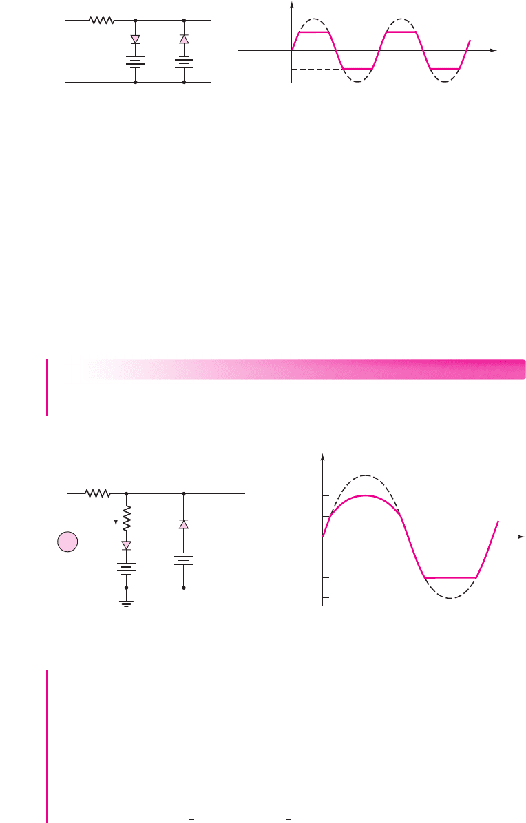
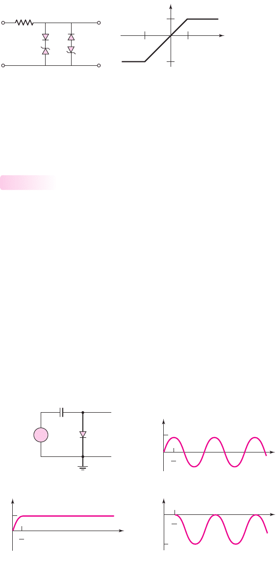
Figure 2.26(a) shows a parallel based clipper circuit using Zener diodes. The
voltage transfer characteristics are shown in Figure 2.26(b). The performance of the
circuit in Figure 2.26(a) is essentially the same as that shown in Figure 2.22.
Clampers
Clamping shifts the entire signal voltage by a dc level. In steady state, the output
waveform is an exact replica of the input waveform, but the output signal is shifted
by a dc value that depends on the circuit. The distinguishing feature of a clamper is
that it adjusts the dc level without needing to know the exact waveform.
An example of clamping is shown in Figure 2.27(a). The sinusoidal input volt-
age signal is shown in Figure 2.27(b). Assume that the capacitor is initially un-
charged. During the first 90 degrees of the input waveform, the voltage across the
capacitor follows the input, and
v
C
= v
I
(assuming that
r
f
= 0
and
V
γ
= 0
). After
v
I
and
v
C
reach their peak values,
v
I
begins to decrease and the diode becomes reverse
biased. Ideally, the capacitor cannot discharge, so the voltage across the capacitor re-
mains constant at
v
C
= V
M
. By Kirchhoff’s voltage law
v
O
=−v
C
+v
I
=−V
M
+ V
M
sin ωt
(2.36(a))
or
v
O
= V
M
(sin ωt − 1)
(2.36(b))
2.3.2
R
D
1
D
2
V
Z1
V
Z2
v
O
+
+
–
–
+
–
v
I
+
–
V
Z1
+ V
g
– (V
Z2
+ V
g
)
– (V
Z2
+ V
g
) V
Z1
+ V
g
v
O
v
I
(a) (b)
Figure 2.26 (a) Parallel-based clipper circuit using Zener diodes; (b) voltage transfer
characteristics
T
4
V
M
0
v
C
t
v
O
–2 V
M
0
t
T
4
v
I
V
M
T
4
0
t
+
–
~
v
I
+
v
O
+ v
C
–
–
(a) (b)
(c) (d)
Figure 2.27 Action of a diode clamper circuit: (a) a typical diode clamper circuit, (b) the
sinusoidal input signal, (c) the capacitor voltage, and (d) the output voltage
nea80644_ch02_067-124.qxd 06/08/2009 07:28 PM Page 94 F506 Tempwork:Dont' Del Rakesh:June:Rakesh 06-08-09:MHDQ134-02 Folder:M
Chapter 2 Diode Circuits 95
The capacitor and output voltages are shown in Figures 2.27(c) and (d). The
output voltage is “clamped” at zero volts, that is,
v
O
≤ 0
. In steady state, the
waveshapes of the input and output signals are the same, and the output signal is
shifted by a certain dc level compared to the input signal.
A clamping circuit that includes an independent voltage source V
B
is shown in
Figure 2.28(a). In this circuit, the R
L
C time constant is assumed to be large, where R
L
is the load resistance connected to the output. If we assume, for simplicity, that
r
f
= 0
and
V
γ
= 0
, then the output is clamped at V
B
. Figure 2.28(b) shows an exam-
ple of a sinusoidal input signal and the resulting output voltage signal. When the
polarity of V
B
is as shown, the output is shifted in a negative voltage direction. Simi-
larly, Figure 2.28(c) shows a square-wave input signal and the resulting output volt-
age signal. For the square-wave signal, we have neglected the diode capacitance
effects and assume the voltage can change instantaneously.
Electronic signals tend to lose their dc levels during signal transmission. For
example, the dc level of a TV signal may be lost during transmission, so that the dc
level must be restored at the TV receiver. The following example illustrates this
effect.
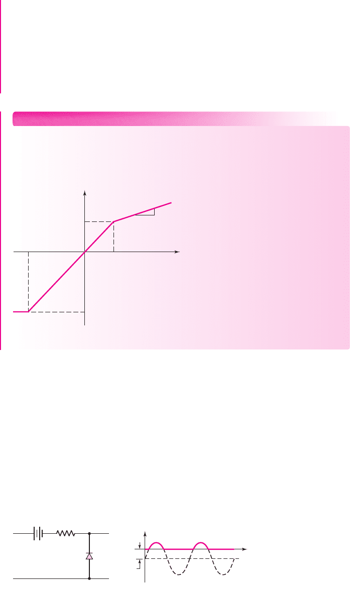
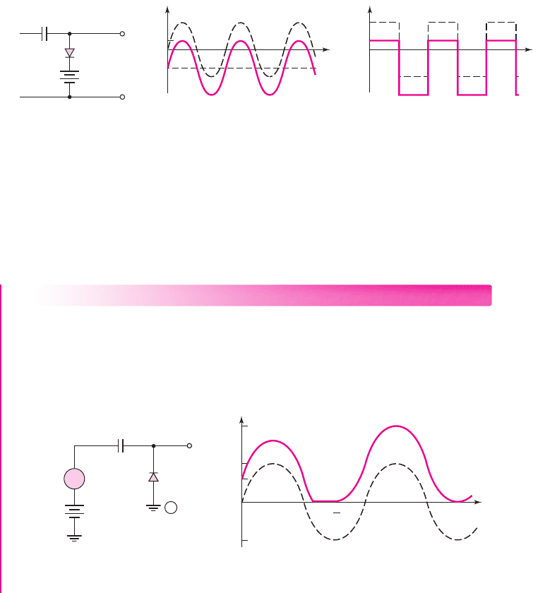
EXAMPLE 2.8
Objective: Find the steady-state output of the diode-clamper circuit shown in Fig-
ure 2.29(a).
The input
v
I
is assumed to be a sinusoidal signal whose dc level has been shifted
with respect to a receiver ground by a value V
B
during transmission. Assume
V
γ
= 0
and
r
f
= 0
for the diode.
+
–
v
O
+
–
v
S
C
+
–
V
B
v
V
B
v
I
v
O
0
t
v
V
B
v
I
v
O
0
t
(a) (b) (c)
Figure 2.28 Action of a diode clamper circuit with a voltage source assuming an ideal diode
(V
r
= 0)
: (a) the circuit, (b) steady-state sinusoidal input and output signals, and (c) steady-
state square-wave input and output signals
v
I
=
V
S
sin wt
V
S
2 V
S
–V
S
V
B
t
1
T
T
t
v
O
v
I
V
C
V
B
v
O
+
+
–
–
(a) (b)
C
3
4
0
A
+
–
Figure 2.29 (a) Circuit for Example 2.8; (b) input and output waveforms
nea80644_ch02_067-124.qxd 06/08/2009 07:28 PM Page 95 F506 Tempwork:Dont' Del Rakesh:June:Rakesh 06-08-09:MHDQ134-02 Folder:M
96 Part 1 Semiconductor Devices and Basic Applications
Solution: Figure 2.29(b) shows the sinusoidal input signal. If the capacitor is ini-
tially uncharged, then the output voltage is
v
O
= V
B
at
t = 0
(diode reverse-biased).
For
0 ≤ t ≤ t
1
, the effective RC time constant is infinite, the voltage across the ca-
pacitor does not change, and
v
O
= v
I
+ V
B
.
At
t = t
1
, the diode becomes forward biased; the output cannot go negative, so
the voltage across the capacitor changes (the
r
f
C
time constant is zero).
At
t = (
3
4
)T
, the input signal begins increasing and the diode becomes reverse
biased, so the voltage across the capacitor now remains constant at
V
C
= V
S
− V
B
with the polarity shown. The output voltage is now given by
v
O
= (V
S
− V
B
) + v
I
+ V
B
= (V
S
− V
B
) + V
S
sin ωt + V
B
or
v
O
= V
S
(1 + sin ωt)
Comment: For
t >(
3
4
)T
, steady state is reached. The output signal waveform is an
exact replica of the input signal waveform and is now measured with respect to the
reference ground at terminal A.
EXERCISE PROBLEM
Ex 2.8: Sketch the steady-state output voltage for the input signal given for the
circuit shown in Figure 2.30. Assume
V
γ
= r
f
= 0
. (Ans. Square wave between
+2V
and
−8V
)
++
––
–
+5 V
–5 V
v
I
v
I
v
O
C
R
V
B
= 2 V
+
D
Figure 2.30 Figure for Exercise Ex 2.8
Test Your Understanding
TYU 2.8 Consider the circuit in Figure 2.23(a). Let
R
1
= 5
k
,
R
2
= 2k
,
V
1
= 1
V, and
V
2
= 3
V. Let
V
γ
= 0.7
V for each diode. Plot the voltage transfer
characteristics (
v
O
versus
v
I
)
for
−5 ≤ v
I
≤ 5
V. (Ans. For
v
I
≤−3.7
V,
v
O
=−3.7
V; for
−3.7 ≤ v
I
≤ 1.7
V,
v
O
= v
I
; for
v
I
≥ 1.7
V,
v
O
= 0.286 v
I
+1.21)
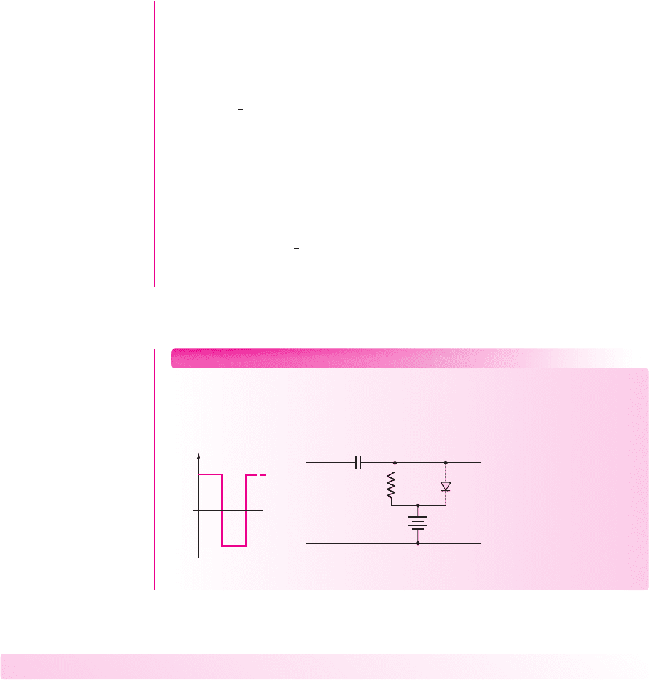
TYU 2.9 Determine the steady-state output voltage
v
O
for the circuit in
Figure 2.31(a), if the input is as shown in Figure 2.31(b). Assume the diode cut-in
voltage is
V
γ
= 0
. (Ans. Output is a square wave between +5 V and +35 V)
nea80644_ch02_067-124.qxd 06/08/2009 07:28 PM Page 96 F506 Tempwork:Dont' Del Rakesh:June:Rakesh 06-08-09:MHDQ134-02 Folder:M
Chapter 2 Diode Circuits 97
+
–
v
O
+
–
+
–
v
I
V
B
= 5 V
R
L
=
100 kΩ
C = 1
m
F
v
I
(V)
+10
0
–20
t
T = 1 ms
(a) (b)
Figure 2.31 Figure for Exercise TYU 2.9: (a) the circuit and (b) input signal
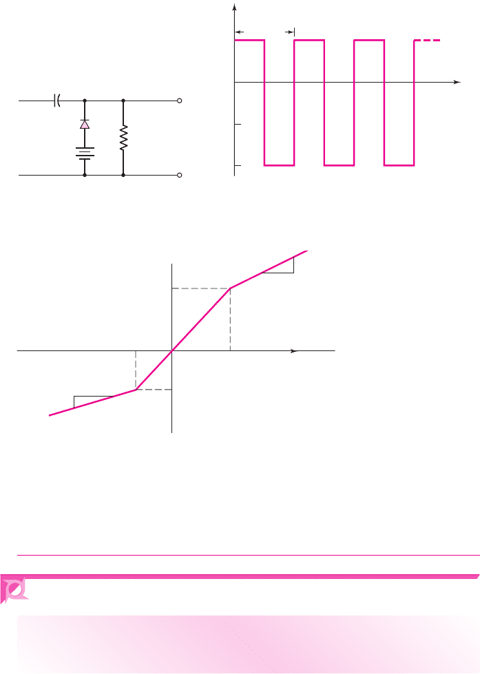
TYU 2.10 Design a parallel-based clipper circuit that will yield the voltage transfer
characteristics shown in Figure 2.32. Assume a diode cut-in voltage of
V
γ
= 0.7
V.
(Ans. From Figure 2.23(a),
V
1
= 2.3
V,
V
2
= 1.3
V,
R
1
= R
2
, include
R
3
in series
with
D
2
, where
R
3
= 0.5R
1
)
2.4 MULTIPLE-DIODE CIRCUITS
Objective: • Examine the techniques used to analyze circuits that
contain more than one diode.
Since a diode is a nonlinear device, part of the analysis of a diode circuit involves de-
termining whether the diode is on or off. If a circuit contains more than one diode, the
analysis is complicated by the various possible combinations of on and off.
In this section, we will look at several multiple-diode circuits. We will see, for
example, how diode circuits can be used to perform logic functions. This section
serves as an introduction to digital logic circuits that will be considered in detail in
Chapters 16 and 17.
−2
−2
3
3
1
3
2
1
v
O
v
I
Figure 2.32 Figure for Exercise TYU 2.10
nea80644_ch02_067-124.qxd 06/08/2009 07:28 PM Page 97 F506 Tempwork:Dont' Del Rakesh:June:Rakesh 06-08-09:MHDQ134-02 Folder:M