Neamen D. Microelectronics: Circuit Analysis and Design
Подождите немного. Документ загружается.

108 Part 1 Semiconductor Devices and Basic Applications
The resistance R is then determined as
R =
5 − V
γ
− V
I
I
=
5 − 1.7 −0.2
10
⇒ 310
Comment: Typical LED current-limiting resistor values are in the range of 300 to
350
.
EXERCISE PROBLEM
Ex 2.13: Determine the value of resistance R required to limit the current in the
circuit shown in Figure 2.46 to
I = 15
mA. Assume
V
γ
= 1.7
V,
r
f
= 15
, and
V
I
= 0.2
V in the “low” state. (Ans.
R = 192
)
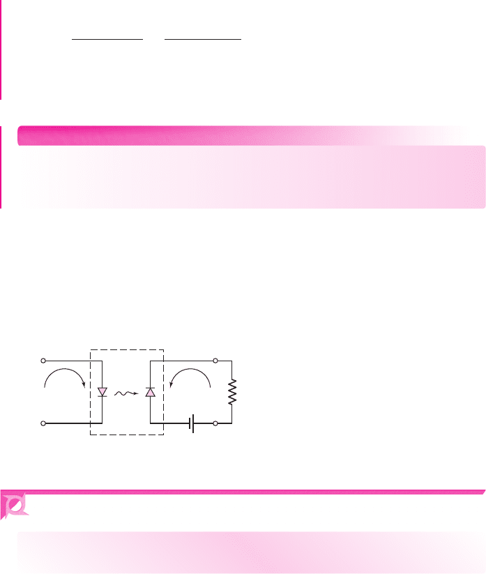
One application of LEDs and photodiodes is in optoisolators, in which the input
signal is electrically decoupled from the output (Figure 2.47). An input signal applied
to the LED generates light, which is subsequently detected by the photodiode. The
photodiode then converts the light back to an electrical signal. There is no electrical
feedback or interaction between the output and input portions of the circuit.
+ –
R
L
I
2
I
1
hν
Input
signal
Isolated
output
signal
LED photodiode
Figure 2.47 Optoisolator using an LED and a photodiode
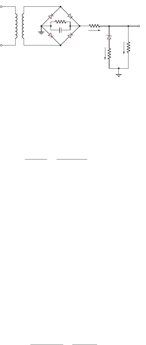
2.6 DESIGN APPLICATION: DC POWER SUPPLY
Objective: • Design a dc power supply to meet a set of specifications.
Specifications: The output load current is to vary between 25 and 50 mA while the
output voltage is to remain in the range
12 ≤ v
O
≤ 12.2
V.
Design Approach: The circuit configuration to be designed is shown in Figure 2.48.
A diode bridge circuit with an RC filter will be used and a Zener diode will be in par-
allel with the output load.
Choices: An ac input voltage with an rms value in the range
110 ≤ v
I
≤ 120
V and
at 60 Hz is available. A Zener diode with a Zener voltage of
V
ZO
= 12
V and a Zener
resistance of
2
that can operate over a current range of
10 ≤ I
Z
≤ 100
mA is avail-
able. Also, a transformer with an 8:1 turns ratio is available.
Solution: With an 8:1 transformer turns ratio, the peak value of
v
S
is in the range
19.4 ≤ v
S
≤ 21.2
V. Assuming diode turn-on voltages of
V
γ
= 0.7V
, the peak value
of
v
O1
is in the range
18.0 ≤ v
O1
≤ 19.8V
.
nea80644_ch02_067-124.qxd 06/08/2009 07:28 PM Page 108 F506 Tempwork:Dont' Del Rakesh:June:Rakesh 06-08-09:MHDQ134-02 Folder:
Chapter 2 Diode Circuits 109
For
v
O1
(max)
and minimum load current, let
I
Z
= 90 mA
. Then
v
O
= V
ZO
+ I
Z
r
z
= 12 +(0.090)(2) = 12.18 V
The input current is
I
i
= I
Z
+ I
L
= 90 +25 = 115 mA
The input resistance R
i
must then be
R
i
=
v
O1
−v
O
I
i
=
19.8 − 12.18
0.115
= 66.3
The minimum Zener current occurs for
I
L
(max)
and
v
O1
(min)
. The voltage
v
O1
(min)
occurs for
v
S
(min)
and must also take into account the ripple voltage. Let
I
Z
(min) = 20
mA. Then the output voltage is
v
O
= V
ZO
+ I
Z
r
Z
= 12 +(0.020)(2) = 12.04 V
The output voltage is within the specified range of output voltage.
We now find
I
i
= I
Z
+ I
L
= 20 +50 = 70 mA
and
v
O1
(min) = I
i
R
i
+v
O
= (0.070)(66.3) +12.04
or
v
O1
(min) = 16.68 V
The minimum ripple voltage of the filter is then
V
r
= v
S
(min) − 1.4 −v
O1
(min) = 19.4 −1.4 − 16.68
or
V
r
= 1.32 V
Now, let
R
1
= 500
. The effective resistance to ground from
v
O1
is
R
1
R
i,eff
where
R
i,eff
is the effective resistance to ground through R
i
and the other circuit ele-
ments. We can approximate
R
i,eff
≈
v
S
(avg) −1.4
I
i
(max)
=
20.3 − 1.4
0.115
= 164
+
+
–
–
v
I
+
–
v
S
v
o1
R
i
D
4
N
1
: N
2
D
1
R
C
D
3
D
2
I
i
I
Z
I
L
R
L
v
O
r
Z
V
ZO
Figure 2.48 DC power supply circuit for design application
nea80644_ch02_067-124.qxd 06/08/2009 07:28 PM Page 109 F506 Tempwork:Dont' Del Rakesh:June:Rakesh 06-08-09:MHDQ134-02 Folder:

110 Part 1 Semiconductor Devices and Basic Applications
Then
R
1
R
i,eff
= 500164 = 123.5
. The required filter capacitance is found from
C =
V
M
2 fRV
r
=
19.8
2(60)(123.5)(1.32)
⇒ 1012 μF
Comments: To obtain the proper output voltage in this design, an appropriate Zener
diode must be available. We will see in Chapter 9 how an op-amp can be incorporated
to provide a more flexible design.
2.7
SUMMARY
• Diode circuits, taking advantage of the nonlinear
i–v
characteristics of the pn
junction, were analyzed and designed in this chapter.
• Half-wave and full-wave rectifier circuits convert a sinusoidal (i.e., ac) signal to
an approximate dc signal. A dc power supply, which is used to bias electronic
circuits and systems, utilizes these types of circuits. An RC filter can be con-
nected to the output of the rectifier circuit to reduce the ripple effect.
• Zener diodes operate in the reverse-breakdown region and are used in voltage
reference or regulator circuits. The percent regulation, a figure of merit for reg-
ulator circuits, was defined and determined for various regulator circuits.
• Techniques used to analyze multidiode circuits were developed. The technique
requires making assumptions as to whether a diode is conducting (on) or not
conducting (off). After analyzing the circuit using these assumptions, we must
go back and verify that the assumptions made were valid.
• Diode circuits can be designed to perform basic digital logic functions, such as
the AND and OR function. However, there are some inconsistencies between
input and output logic values as well as some loading effects, which will
severely limit the use of diode logic gates as stand-alone circuits.
• The LED converts electrical current to light and is used extensively in such
applications as the seven-segment alphanumeric display. Conversely, the
photodiode detects an incident light signal and transforms it into an electrical
current.
• As an application, a simple dc power supply was designed using a rectifier
circuit in conjunction with a Zener diode.
CHECKPOINT
After studying this chapter, the reader should have the ability to:
✓ In general, apply the diode piecewise linear model in the analysis of diode
circuits.
✓ Analyze diode rectifier circuits, including the calculation of ripple voltage.
✓ Analyze Zener diode circuits, including the effect of a Zener resistance.
✓ Determine the output signal for a given input signal of diode clipper and clam-
per circuits.
✓ Analyze circuits with multiple diodes by making initial assumptions and then
verifying these initial assumptions.
nea80644_ch02_067-124.qxd 06/10/2009 07:47 PM Page 110 F506 Tempwork:Dont' Del Rakesh:June:Rakesh 06-10-09:MHDQ134-02:

Chapter 2 Diode Circuits 111
REVIEW QUESTIONS
1. What characteristic of a diode is used in the design of diode signal processing
circuits?
2. Describe a simple half-wave diode rectifier circuit and sketch the output voltage
versus time.
3. Describe a simple full-wave diode rectifier circuit and sketch the output voltage
versus time.
4. What is the advantage of connecting an RC filter to the output of a diode recti-
fier circuit?
5. Define ripple voltage. How can the magnitude of the ripple voltage be reduced?
6. Describe a simple Zener diode voltage reference circuit.
7. What effect does the Zener diode resistance have on the voltage reference circuit
operation? Define load regulation.
8. What are the general characteristics of diode clipper circuits?
9. Describe a simple diode clipper circuit that limits the negative portion of a sinu-
soidal input voltage to a specified value.
10. What are the general characteristics of diode clamper circuits?
11. What one circuit element, besides a diode, is present in all diode clamper
circuits?
12. Describe the procedure used in the analysis of a circuit containing two diodes.
How many initial assumptions concerning the state of the circuit are possible?
13. Describe a diode OR logic circuit. Compare a logic 1 value at the output com-
pared to a logic 1 value at the input. Are they the same value?
14. Describe a diode AND logic circuit. Compare a logic 0 value at the output com-
pared to a logic 0 value at the input. Are they the same value?
15. Describe a simple circuit that can be used to turn an LED on or off with a high
or low input voltage.
PROBLEMS
[Note: In the following problems, assume
r
f
= 0
unless otherwise specified.]
Section 2.1 Rectifier Circuits
2.1 Consider the circuit shown in Figure P2.1. Let
R = 1
k
,
V
γ
= 0.6
V, and
r
f
= 20
. (a) Plot the voltage transfer characteristics
v
O
versus
v
I
over the
range
−10 ≤ v
I
≤ 10
V. (b) Assume
v
I
= 10 sin ω t
(V). (i) Sketch
v
O
versus time for the sinusoidal input. (ii) Find the average value of
v
O
.
(iii) Determine the peak diode current. (iv) What is the PIV of the diode?
2.2 For the circuit shown in Figure P2.1, show that for
v
I
≥ 0
, the output volt-
age is approximately given by
v
O
= v
I
− V
T
ln
v
O
I
S
R
2.3 A half-wave rectifier such as shown in Figure 2.2(a) has a 2 k
load.
The input is a 120 V (rms), 60 Hz signal and the transformer is a 10:1 step-
down transformer. The diode has a cut-in voltage of
V
γ
= 0.7
V
(r
f
= 0)
.
(a) What is the peak output voltage? (b) Determine the peak diode current.
+
–
v
o
R
D
+
–
v
I
Figure P2.1
nea80644_ch02_067-124.qxd 06/10/2009 07:47 PM Page 111 F506 Tempwork:Dont' Del Rakesh:June:Rakesh 06-10-09:MHDQ134-02:

112 Part 1 Semiconductor Devices and Basic Applications
R
+
–
V
B
N
1
N
2
N
2
+
–
v
I
+
–
v
S
D
1
D
2
+
–
v
S
Figure P2.5
(c) What is the fraction (percent) of a cycle that
v
O
> 0
. (d) Determine the
average output voltage. (e) Find the average current in the load.
2.4 Consider the battery charging circuit shown in Figure 2.4(a). Assume that
V
B
= 9
V,
V
S
= 15
V, and
ω = 2π(60)
. (a) Determine the value of
R
such
that the average battery charging current is
i
D
= 0.8
A. (b) Find the fraction
of time that the diode is conducting.
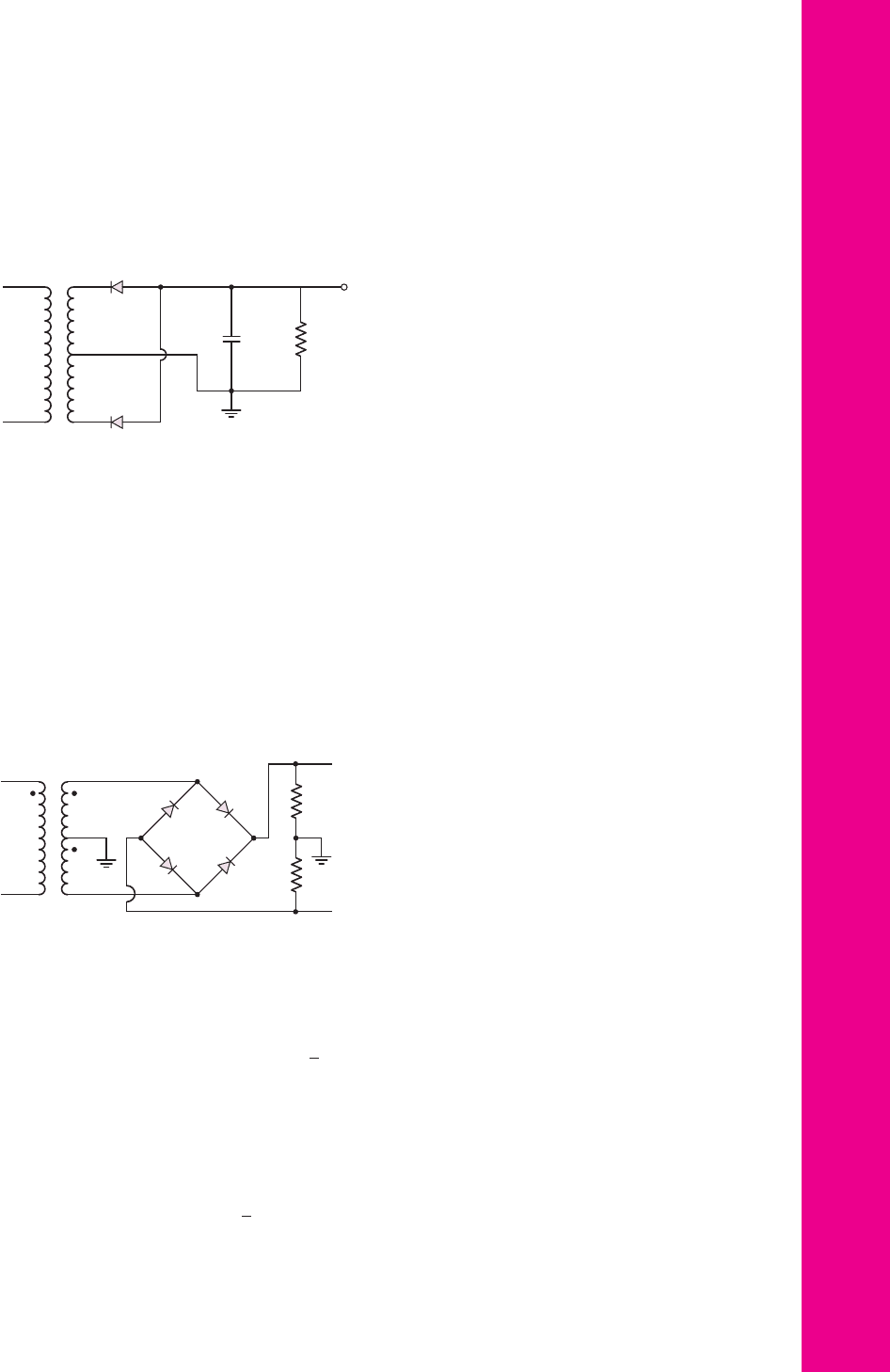
2.5 Figure P2.5 shows a simple full-wave battery charging circuit. Assume
V
B
= 9
V,
V
γ
= 0.7
V, and
v
S
= 15 sin[2π(60)t]
(V). (a) Determine
R
such
that the peak battery charging current is 1.2 A. (b) Determine the average
battery charging current. (c) Determine the fraction of time that each diode
is conducting.
2.6 The full-wave rectifier circuit shown in Figure 2.5(a) in the text is to deliver
0.2 A and 12 V (peak values) to a load. The ripple voltage is to be limited to
0.25 V. The input signal is 120 V (rms) at 60 Hz. Assume diode cut-in voltages
of 0.7 V. (a) Determine the required turns ratio of the transformer. (b) Find the
required value of the capacitor. (c) What is the PIV rating of the diode?
2.7 The input signal voltage to the full-wave rectifier circuit in Figure 2.6(a) in
the text is
v
I
= 160 sin[2π(60)t]V
. Assume
V
γ
= 0.7V
for each diode.
Determine the required turns ratio of the transformer to produce a peak
output voltage of (a) 25 V, and (b) 100 V. (c) What must be the diode PIV
rating for each case?
2.8 The output resistance of the full-wave rectifier in Figure 2.6(a) in the text is
R = 150
. A filter capacitor is connected in parallel with R. Assume
V
γ
= 0.7
V. The peak output voltage is to be 12 V and the ripple voltage is
to be no more than 0.3 V. The input frequency is 60 Hz. (a) Determine the
required rms value of
v
S
. (b) Determine the required filter capacitance
value. (c) Determine the peak current through each diode.
2.9 Repeat Problem 2.8 for the half-wave rectifier in Figure 2.2(a).
2.10 Consider the half-wave rectifier circuit shown in Figure 2.8(a) in the text.
Assume
v
S
= 10 sin[2π(60)t]
(V),
V
γ
= 0.7
V, and
R = 500
. (a) What is
the peak output voltage? (b) Determine the value of capacitance required
such that the ripple voltage is no more that
V
r
= 0.5
V. (c) What is the PIV
rating of the diode?
2.11 The parameters of the half-wave rectifier circuit in Figure 2.8(a) in the
text are
R = 1
k
,
C = 350 μ
F, and
V
γ
= 0.7
V. Assume
v
S
(t) =
V
S
sin[2π(60)t]
(V) where
V
S
is in the range of
11 ≤ V
S
≤ 13
V. (a) What
is the range in output voltage? (b) Determine the range in ripple voltage. (c)
If the ripple voltage is to be limited to
V
r
= 0.4
V, determine the minimum
value of capacitance required.
nea80644_ch02_067-124.qxd 06/08/2009 07:28 PM Page 112 F506 Tempwork:Dont' Del Rakesh:June:Rakesh 06-08-09:MHDQ134-02 Folder:
Chapter 2 Diode Circuits 113
2.13 Consider the full-wave rectifier circuit in Figure 2.7 of the text. The output
resistance is
R
L
= 125
, each diode cut-in voltage is
V
γ
= 0.7V
, and the
frequency of the input signal is 60 Hz. A filter capacitor is connected in par-
allel with R
L
. The magnitude of the peak output voltage is to be 15 V and the
ripple voltage is to be no more than 0.35 V. (a) Determine the rms value of
v
S
and (b) the required value of the capacitor.
2.14 The circuit in Figure P2.14 is a complementary output rectifier. If
v
s
= 26
sin
[2π(60)t]V
, sketch the output waveforms
v
+
o
and
v
−
o
versus time, as-
suming
V
γ
= 0.6
V for each diode.
+
–
v
I
+
–
v
S
V
O
D
1
D
2
CR
+
–
v
S
Figure P2.12
+
–
v
s
+
–
v
s
+
–
v
i
v
o
+
v
o
–
R
R
Figure P2.14
2.12 The full-wave rectifier circuit shown in Figure P2.12 has an input signal
whose frequency is 60 Hz. The rms value of
v
S
= 8.5V
. Assume each diode
cut-in voltage is
V
γ
= 0.7V
. (a) What is the maximum value of V
O
? (b) If
R = 10
, determine the value of C such that the ripple voltage is no larger
than 0.25 V. (c) What must be the PIV rating of each diode?
2.15 A full-wave rectifier is to be designed using the center-tapped transformer
configuration. The peak output voltage is to be 12 V, the nominal load
current is to be 0.5 A, and the ripple voltage is to be limited to 3 percent.
Assume
V
γ
= 0.8
V and let
v
I
= 120
√
2 sin[2π(60)t]
V. (a) What is the
transformer turns ratio? (b) What is the minimum value of
C
required?
(c) What is the peak diode current? (d) Determine the average diode current.
(e) What is the PIV rating of the diodes.
2.16 A full-wave rectifier is to be designed using the bridge circuit configuration.
The peak output voltage is to be 9 V, the nominal load current is to be 100
mA, and the ripple voltage is to be limited to
V
r
= 0.2
V. Assume
V
γ
= 0.8
V and let
v
I
= 120
√
2 sin[2π(60)t]
(V). (a) What is the trans-
former turns ratio? (b) What is the minimum value of
C
required? (c) What
nea80644_ch02_067-124.qxd 06/08/2009 07:28 PM Page 113 F506 Tempwork:Dont' Del Rakesh:June:Rakesh 06-08-09:MHDQ134-02 Folder:
114 Part 1 Semiconductor Devices and Basic Applications
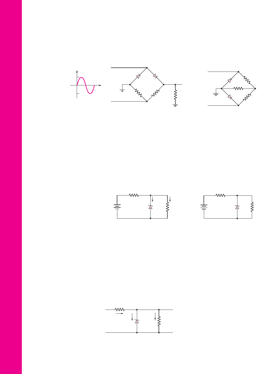
*2.18 (a) Sketch
v
o
versus time for the circuit in Figure P2.18. The input is a sine
wave given by
v
i
= 10 sin ωt
V. Assume
V
γ
= 0
. (b) Determine the rms
value of the output voltage.
Section 2.2 Zener Diode Circuits
2.19 Consider the circuit shown in Figure P2.19. The Zener diode voltage is
V
Z
= 3.9
V and the Zener diode incremental resistance is
r
z
= 0
. (a) Deter-
mine
I
Z
, I
L
, and the power dissipated in the diode. (b) Repeat part (a) if the
4 k
load resistor is increased to 10 k
.
+
–
v
i
R
L
=
2.2 kΩ
R
1
=
2.2 kΩ
R
2
=
2.2 kΩ
D
1
D
2
v
o
v
i
+40
–40
Figure P2.17
+
+
–
–
v
i
v
o
R
1
=
2.2 kΩ
R
2
=
2.2 kΩ
R
L
= 6.8 kΩ
D
1
D
2
Figure P2.18
+
–
20 V
I
Z
+
–
V
Z
12 kΩ
4 kΩ
I
L
Figure P2.19
+
–
40 V
+
–
V
Z
120 Ω
R
L
Figure P2.20
+
–
V
I
+
–
V
L
+
–
V
Z
I
I
R
i
I
Z
I
L
R
L
Figure P2.21
2.20 Consider the Zener diode circuit shown in Figure P2.20. Assume
V
Z
= 12
V
and
r
z
= 0
. (a) Calculate the Zener diode current and the power dissipated
in the Zener diode for
R
L
=∞
. (b) What is the value of R
L
such that the
current in the Zener diode is one-tenth of the current supplied by the 40 V
source? (c) Determine the power dissipated in the Zener diode for the
conditions of part (b).
2.21 Consider the Zener diode circuit shown in Figure P2.21. Let
V
I
= 60
V,
R
i
= 150
, and
V
ZO
= 15.4
V. Assume
r
z
= 0
. The power rating of the
diode is 4 W and the minimum diode current is to be 15 mA. (a) Determine
the range of diode currents. (b) Determine the range of load resistance.
is the peak diode current? (d) Determine the average diode current. (e) What
is the PIV rating of the diodes.
*2.17 Sketch
v
o
versus time for the circuit in Figure P2.17 with the input shown.
Assume
V
γ
= 0
.
nea80644_ch02_067-124.qxd 06/08/2009 07:28 PM Page 114 F506 Tempwork:Dont' Del Rakesh:June:Rakesh 06-08-09:MHDQ134-02 Folder:

Chapter 2 Diode Circuits 115
*2.22 In the voltage regulator circuit in Figure P2.21,
V
I
= 20
V,
V
Z
= 10
V,
R
i
= 222
, and
P
Z
(max) = 400
mW. (a) Determine I
L
, I
Z
, and I
I
,if
R
L
= 380
. (b) Determine the value of R
L
that will establish P
Z
(max) in
the diode. (c) Repeat part (b) if
R
i
= 175
.
2.23 A Zener diode is connected in a voltage regulator circuit as shown in Fig-
ure P2.21. The Zener voltage is
V
Z
= 10
V and the Zener resistance is
assumed to be
r
z
= 0
. (a) Determine the value of R
i
such that the Zener
diode remains in breakdown if the load current varies from
I
L
= 50
to
500 mA and if the input voltage varies from
V
I
= 15
to 20 V. Assume
I
Z
(min) = 0.1I
Z
(max)
. (b) Determine the power rating required for the
Zener diode and the load resistor.
2.24 Consider the Zener diode circuit in Figure 2.19 in the text. Assume parameter
values of
V
ZO
= 5.6
V (diode voltage when
I
Z
∼
=
0)
,
r
z
= 3
, and
R
i
= 50
. Determine
V
L
,
I
Z
,
I
L
, and the power dissipated in the diode for
(a)
V
PS
= 10
V,
R
L
=∞
; (b)
V
PS
= 10
V,
R
L
= 200
; (c)
V
PS
= 12
V,
R
L
=∞
; and (d)
V
PS
= 12
V,
R
L
= 200
.
D2.25 Design a voltage regulator circuit such as shown in Figure P2.21 so that
V
L
= 7.5
V. The Zener diode voltage is
V
Z
= 7.5
V at
I
Z
= 10
mA. The in-
cremental diode resistance is
r
z
= 12
. The nominal supply voltage is
V
I
= 12
V and the nominal load resistance is
R
L
= 1
k
. (a) Determine
R
i
.
(b) If
V
I
varies by
±10
percent, calculate the source regulation. What is
the variation in output voltage? (c) If
R
L
varies over the range of
1
k
≤ R
L
≤∞
, what is the variation in output voltage? Determine the load
regulation.
2.26 The percent regulation of the Zener diode regulator shown in Figure 2.16 is
5 percent. The Zener voltage is
V
ZO
= 6
V and the Zener resistance is
r
z
= 3
. Also, the load resistance varies between 500 and
1000
, the
input resistance is
R
i
= 280
, and the minimum power supply voltage is
V
PS
(min) = 15
V. Determine the maximum power supply voltage allowed.
*2.27 A voltage regulator is to have a nominal output voltage of 10 V. The speci-
fied Zener diode has a rating of 1 W, has a 10 V drop at
I
Z
= 25
mA, and
has a Zener resistance of
r
z
= 5
. The input power supply has a nominal
value of
V
PS
= 20
V and can vary by
±25
percent. The output load current
is to vary between
I
L
= 0
and 20 mA. (a) If the minimum Zener current is
to be
I
Z
= 5
mA, determine the required R
i
. (b) Determine the maximum
variation in output voltage. (c) Determine the percent regulation.
*2.28 Consider the circuit in Figure P2.28. Let
V
γ
= 0
. The secondary voltage is
given by
v
s
= V
s
sin ωt
, where
V
s
= 24
V. The Zener diode has parameters
V
Z
= 16
V at
I
Z
= 40
mA and
r
z
= 2
. Determine R
i
such that the load
current can vary over the range
40 ≤ I
L
≤ 400
mA with
I
Z
(min) = 40
mA
and find C such that the ripple voltage is no larger than 1 V.
+
–
v
s
+
–
v
s
+
–
v
i
+
–
V
L
+
–
V
Z
I
L
I
Z
C
R
i
R
L
Figure P2.28
nea80644_ch02_067-124.qxd 06/08/2009 07:28 PM Page 115 F506 Tempwork:Dont' Del Rakesh:June:Rakesh 06-08-09:MHDQ134-02 Folder:
116 Part 1 Semiconductor Devices and Basic Applications
*2.29 The secondary voltage in the circuit in Figure P2.28 is
v
s
= 12 sin ωt
V. The
Zener diode has parameters
V
Z
= 8
V at
I
Z
= 100
mA and
r
z
= 0.5
. Let
V
γ
= 0
and
R
i
= 3
. Determine the percent regulation for load currents
between
I
L
= 0.2
and 1 A. Find C such that the ripple voltage is no larger
than 0.8 V.
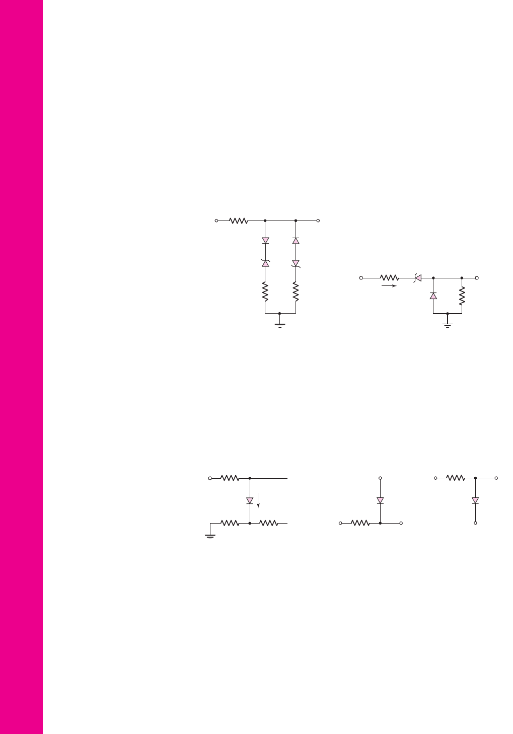
Section 2.3 Clipper and Clamper Circuits
2.30 The parameters in the circuit shown in Figure P2.30 are
V
γ
= 0.7
V,
V
Z1
= 2.3
V, and
V
Z2
= 5.6
V. Plot
v
O
versus
v
I
over the range of
−10 ≤ v
I
≤+10
V.
2.31 Consider the circuit in Figure P2.31. Let
V
γ
= 0
. (a) Plot
v
O
versus
v
I
over
the range
−10 ≤ v
I
≤+10 V
. (b) Plot i
1
over the same input voltage range
as part (a).
2.32 For the circuit in Figure P2.32, (a) plot
v
O
versus
v
I
for
0 ≤ v
I
≤ 15
V. As-
sume
V
γ
= 0.7
V. Indicate all breakpoints. (b) Plot i
D
over the same range
of input voltage. (c) Compare the results of parts (a) and (b) with a computer
simulation.
R
1
=
1 kΩ
R = 0.5 kΩ
R
2
=
2 kΩ
–
+
+
–
V
Z1
V
Z2
D
1
D
2
v
I
v
O
Figure P2.30
v
I
v
O
10 kΩ
10 kΩ
V
Z
= 3 V
+–
i
1
Figure P2.31
v
o
i
D
+ 15 V
2 kΩ
v
I
1 kΩ
1 kΩ
Figure P2.32
2.33 Each diode cut-in voltage is 0.7 V for the circuits shown in Figure P2.33.
(a) Plot
v
O
versus
v
I
over the range
−5 ≤ v
I
≤+5
V for the circuit in
Figure P2.33(a) for (i)
V
B
= 1.8
V and (ii)
V
B
=−1.8
V. (b) Repeat part
(a) for the circuit shown in Figure P2.33(b).
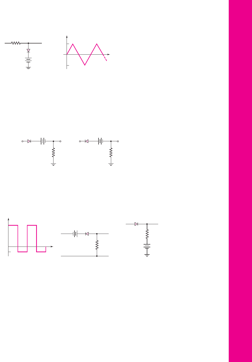
*2.34 The diode in the circuit of Figure P2.34(a) has piecewise linear parameters
V
γ
= 0.7
V and
r
f
= 10
. (a) Plot
v
O
versus
v
I
for
−30 ≤ v
I
≤ 30
V. (b) If
the triangular wave, shown in Figure P2.34(b), is applied, plot the output
versus time.
v
O
D
R = 4 kΩ
v
I
V
B
v
O
D
R = 4 kΩ
v
I
V
B
(
a
)
(
b
)
Figure P2.33
nea80644_ch02_067-124.qxd 06/08/2009 08:41 PM Page 116 F506 Tempwork:Dont' Del Rakesh:June:Rakesh 06-08-09:MHDQ134-02 Folder:
Chapter 2 Diode Circuits 117
2.35 Consider the circuits shown in Figure P2.35. Each diode cut-in voltage is
V
γ
= 0.7
V. (a) Plot
v
O
versus
v
I
over the range
−10 ≤ v
I
≤+10
V for
the circuit in Figure P2.35(a) for (i)
V
B
= 5
V and (ii)
V
B
=−5
V. (b) Re-
peat part (a) for the circuit in Figure P2.35(b).
v
O
v
I
+–
V
B
(
a
)(
b
)
R =
6.8 kΩ
D
v
O
v
I
+–
V
B
R =
6.8 kΩ
D
Figure P2.35
(
a
)
(
b
)
v
I
t
30 V
–30 V
v
O
v
I
R = 100 Ω
+
10 V
–
Figure P2.34
2.36 Plot
v
O
for each circuit in Figure P2.36 for the input shown. Assume
(a)
V
γ
= 0
and (b)
V
γ
= 0.6
V.
–5 V
0
20 V
v
I
+
–
v
I
+
–
–
+
v
O
10 kΩ
2 V
v
O
v
I
2.2 kΩ
5 V
+
–
(a) (b)
Figure P2.36
2.37 Consider the parallel clipper circuit in Figure 2.26 in the text. Assume
V
Z1
= 6
V,
V
Z2
= 4
V, and
V
γ
= 0.7
V for all diodes. For
v
I
= 10 sin ωt,
sketch
v
O
versus time over two periods of the input signal.
*2.38 A car’s radio may be subjected to voltage spikes induced by coupling from
the ignition system. Pulses on the order of
±250
V and lasting for 120
μ
s
may exist. Design a clipper circuit using resistors, diodes, and Zener diodes
to limit the input voltage between +14 V and −0.7 V. Specify power ratings
of the components.
nea80644_ch02_067-124.qxd 06/08/2009 08:41 PM Page 117 F506 Tempwork:Dont' Del Rakesh:June:Rakesh 06-08-09:MHDQ134-02 Folder: