Neamen D. Microelectronics: Circuit Analysis and Design
Подождите немного. Документ загружается.

418 Part 1 Semiconductor Devices and Basic Applications
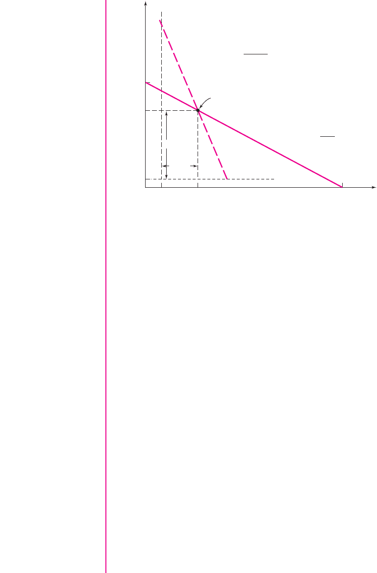
The ac load line, from Figure 6.46(c), is
V
ce
=−I
c
(R
C
R
L
) =−I
c
(4.12)
These two load lines are plotted in Figure 6.47. At this point, the Q-point is unknown.
Also shown in the figure are the
I
C
(min)
and
V
CE
(min)
values. The peak value of the
ac collector current is
I
C
and the peak value of the ac collector–emitter voltage is
V
CE
.
We can write
I
C
= I
CQ
− I
C
(min) = I
CQ
−0.1
and
V
CE
= V
CEQ
− V
CE
(min) = V
CEQ
−1
where
I
C
(min)
and
V
CE
(min)
were given in the specifications.
Now
V
CE
= I
C
(R
C
R
L
)
or
V
CEQ
−1 = (I
CQ
−0.1)(4.12)
Substituting the expression for the dc load line, we obtain
10 − I
CQ
(9) − 1 = (I
CQ
−0.1)(4.12)
which yields
I
CQ
= 0.717 mA
and then
V
CEQ
= 3.54 V
i
C
(mA)
I
C
(min)
ΔI
C
ΔV
CE
V
CE
(min)
0
V
CEQ
v
CE
(V)10
I
CQ
1.11
DC load line slope =
–1
9 kΩ
AC load line slope =
–1
4.12 kΩ
Q-point
Figure 6.47 The ac and dc load lines to find the maximum symmetrical swing for the circuit
shown in Figure 6.46(a) used in Example 6.11
nea80644_ch06_369-468.qxd 06/13/2009 07:32 PM Page 418 F506 Hard disk:Desktop Folder:Rakesh:MHDQ134-06:

Chapter 6 Basic BJT Amplifiers 419
Solution (Bias Resistors):
We can now determine
R
1
and
R
2
to produce the desired
Q-point.
From the dc equivalent circuit, we have
V
TH
=
R
2
R
1
+ R
2
[5 − (−5)] −5
=
1
R
1
(R
TH
)(10) − 5 =
1
R
1
(24.2)(10) − 5
Then, from a KVL equation around the B–E loop, we obtain
V
TH
=
I
CQ
β
R
TH
+ V
BE
(on) +
1 + β
β
I
CQ
R
E
−5
or
1
R
1
(24.2)(10) − 5 =
0.717
120
(24.2) + 0.7 +
121
120
(0.717)(2) − 5
which yields
R
1
= 106 k
We then find
R
2
= 31.4k
Symmetrical Swing Results: We then find the peak ac collector current to be
I
C
= I
CQ
− I
C
(min) = 0.717 −0.1 = 0.617
mA
or a peak-to-peak ac collector current to be 1.234 mA. The peak ac collector-emitter
voltage is
V
CE
= V
CEQ
− V
CE
(min) = 3.54 −1 = 2.54
V
or the peak-to-peak ac collector–emitter voltage is 5.08 V.
Comment: We have found the
Q
-point to yield the maximum undistorted ac output
signal. However, tolerances in resistor values or transistor parameters may change
the
Q
-point such that this maximum ac output signal may not be possible without in-
ducing distortion. The effect of tolerances is most easily determined from a computer
analysis.
EXERCISE PROBLEM
Ex 6.11: For the circuit shown in Figure 6.48, let
β = 120
,
V
EB
(on) = 0.7
V, and
r
o
=∞
. (a) Design a bias-stable circuit such that
I
CQ
= 1.6
mA. Determine
V
ECQ
. (b) Determine the value of
R
L
that will produce the maximum symmetri-
cal swing in the output voltage and collector current for
i
C
≥ 0.1
mA and
0.5 ≤ v
EC
≤ 11.5
V. (Ans. (a)
R
1
= 15.24 k
,
R
2
= 58.7k
,
V
ECQ
= 3.99
V
(b)
R
L
= 5.56 k
)
nea80644_ch06_369-468.qxd 06/13/2009 07:32 PM Page 419 F506 Hard disk:Desktop Folder:Rakesh:MHDQ134-06:

420 Part 1 Semiconductor Devices and Basic Applications
Test Your Understanding
TYU 6.8 For the circuit in Figure 6.31, use the parameters given in Exercise Ex 6.5.
If the total instantaneous current must always be greater than 0.1 mA and the total
instantaneous C–E voltage must be in the range
0.5 ≤ v
CE
≤ 5V
, determine the
maximum symmetrical swing in the output voltage. (Ans. 3.82 V peak-to-peak)
TYU 6.9 Consider the circuit in Figure 6.38. Assume transistor and circuit parame-
ters as given in Exercise Ex 6.7, except
R
B
is a variable and
V
A
=∞
. Assume
i
C
≥ 0.1
mA and
v
CE
≥ 0.7
V. (a) Determine the
Q
-point values to yield the maxi-
mum symmetrical swing. (b) What is the maximum swing in the collector current
and the output voltage? (Ans. (a)
I
CQ
= 0.808
mA,
V
CEQ
= 3.53
V; (b) peak-to-
peak values:
I
C
= 1.42
mA,
V
CE
= 5.67
V)
6.6 COMMON-COLLECTOR
(EMITTER-FOLLOWER) AMPLIFIER
Objective: • Analyze the emitter-follower amplifier and become familiar
with the general characteristics of this circuit.
The second type of transistor amplifier to be considered is the common-collector
circuit. An example of this circuit configuration is shown in Figure 6.49. As seen in
the figure, the output signal is taken off of the emitter with respect to ground and the
collector is connected directly to V
CC
. Since V
CC
is at signal ground in the ac equiva-
lent circuit, we have the name common-collector. The more common name for this
circuit is emitter follower. The reason for this name will become apparent as we
proceed through the analysis.
Small-Signal Voltage Gain
The dc analysis of the circuit is exactly the same as we have already seen, so we
will concentrate on the small-signal analysis. The hybrid-
π
model of the bipolar
6.6.1
R
E
= 1 kΩ
C
E
R
L
V
CC
= +12 V
R
1
R
2
C
C2
C
C1
+
–
v
s
R
C
=
4 kΩ
v
o
Figure 6.48 Figure for Exercise Ex 6.11
nea80644_ch06_369-468.qxd 06/13/2009 07:32 PM Page 420 F506 Hard disk:Desktop Folder:Rakesh:MHDQ134-06:
Chapter 6 Basic BJT Amplifiers 421
transistor can also be used in the small-signal analysis of this circuit. Assuming the
coupling capacitor C
C
acts as a short circuit, Figure 6.50 shows the small-signal
equivalent circuit of the circuit shown in Figure 6.49. The collector terminal is at
signal ground and the transistor output resistance r
o
is in parallel with the depen-
dent current source.
+
–
R
1
= 50 kΩ
R
2
= 50 kΩ
R
E
= 2 kΩ
+
–
v
s
V
CC
= 5 V
C
C
v
O
R
S
= 0.5 kΩ
Figure 6.49 Emitter-follower circuit. Output signal
is at the emitter terminal with respect to ground.
C
B
E
R
1
⎜⎜ R
2
R
E
r
o
+
–
V
s
R
S
= 0.5 kΩ
I
b
+
–
V
in
+
–
V
p
r
p
+
–
V
o
b I
b
Figure 6.50 Small-signal equivalent circuit of the emitter-
follower
+
+
–
–
V
p
r
o
R
E
b I
b
V
s
r
p
I
i
I
b
I
o
I
e
V
o
R
o
V
in
B E
R
ib
R
S
= 0.5 kΩ
R
i
R
1
⎜⎜
R
2
+
–
Figure 6.51 Small-signal equivalent circuit of the emitter-follower with all signal grounds
connected together
Figure 6.51 shows the equivalent circuit rearranged so that all signal grounds are
at the same point.
We see that
I
o
= (1 +β)I
b
(6.64)
so the output voltage can be written as
V
o
= I
b
(1 + β)(r
o
R
E
)
(6.65)
Writing a KVL equation around the base-emitter loop, we obtain
V
in
= I
b
[r
π
+(1 +β)(r
o
R
E
)]
(6.66(a))
or
R
ib
=
V
in
I
b
= r
π
+(1 +β)(r
o
R
E
)
(6.66(b))
nea80644_ch06_369-468.qxd 06/13/2009 07:32 PM Page 421 F506 Hard disk:Desktop Folder:Rakesh:MHDQ134-06:

422 Part 1 Semiconductor Devices and Basic Applications
We can also write
V
in
=
R
i
R
i
+ R
S
· V
s
(6.67)
where
R
i
= R
1
R
2
R
ib
.
Combining Equations (6.65), (6.66(b)), and (6.67), the small-signal voltage
gain is
A
v
=
V
o
V
s
=
(1 + β)(r
o
R
E
)
r
π
+(1 +β)(r
o
R
E
)
·
R
i
R
i
+ R
S
(6.68)
EXAMPLE 6.12
Objective: Calculate the small-signal voltage gain of an emitter-follower circuit.
For the circuit shown in Figure 6.49, assume the transistor parameters are:
β = 100
,
V
BE
(on) = 0.7
V, and
V
A
= 80
V.
Solution: The dc analysis shows that
I
CQ
= 0.793
mA and
V
CEQ
= 3.4
V. The
small-signal hybrid-
π
parameters are determined to be
r
π
=
V
T
β
I
CQ
=
(0.026)(100)
0.793
= 3.28 k
g
m
=
I
CQ
V
T
=
0.793
0.026
= 30.5mA/V
and
r
o
=
V
A
I
CQ
=
80
0.793
∼
=
100 k
We may note that
R
ib
= 3.28 +(101)(1002) = 201 k
and
R
i
= 5050201 = 22.2k
The small-signal voltage gain is then
A
v
=
(101)(1002)
3.28 + (101)(1002)
·
22.2
22.2 + 0.5
or
A
v
=+0.962
Comment: The magnitude of the voltage gain is slightly less than 1. An examination
of Equation (6.68) shows that this is always true. Also, the voltage gain is positive,
which means that the output signal voltage at the emitter is in phase with the input
signal voltage. The reason for the terminology emitter-follower is now clear. The ac
output voltage at the emitter is essentially equal to the ac input voltage.
At first glance, a transistor amplifier with a voltage gain essentially of 1 may not
seem to be of much value. However, the input and output resistance characteristics
make this circuit extremely useful in many applications, as we will show in the next
section.
nea80644_ch06_369-468.qxd 06/13/2009 07:32 PM Page 422 F506 Hard disk:Desktop Folder:Rakesh:MHDQ134-06:

Chapter 6 Basic BJT Amplifiers 423
EXERCISE PROBLEM
Ex 6.12: For the circuit shown in Figure 6.49, let
V
CC
= 12
V,
R
E
= 30
,
R
1
= 1.3
k
,
R
2
= 4.2
k
, and
R
S
= 0
. The transistor parameters are
β = 80
,
V
BE
(on) = 0.7
V, and
V
A
= 75
V. (a) Determine the quiescent values
I
EQ
and
V
CEQ
. (b) Find the small-signal voltage gain
A
v
= V
o
/V
s
. (c) Determine the input
resistance looking into the base of the transistor. (Ans. (a)
I
EQ
= 0.2
A,
V
CEQ
= 6
V; (b)
A
v
= 0.9954
; (c)
R
ib
= 2.27
k
)
COMPUTER ANALYSIS EXERCISE
PS 6.4: Perform a PSpice simulation on the circuit in Figure 6.49. (a) Determine
the small-signal voltage gain and (b) find the effective resistance seen by the
signal source
v
s
.
Input and Output Impedance
Input Resistance
The input impedance, or small-signal input resistance for low-frequency signals,
of the emitter-follower is determined in the same manner as for the common-
emitter circuit. For the circuit in Figure 6.49, the input resistance looking into the
base is denoted
R
ib
and is indicated in the small-signal equivalent circuit shown in
Figure 6.51.
The input resistance R
ib
was given by Equation (6.66(b)) as
R
ib
= r
π
+(1 +β)(r
o
R
E
)
Since the emitter current is (
1 + β
) times the base current, the effective
impedance in the emitter is multiplied by (
1 + β
). We saw this same effect when
an emitter resistor was included in a common-emitter circuit. This multiplication
by (
1 + β
) is again called the resistance reflection rule. The input resistance at
the base is
r
π
plus the effective resistance in the emitter multiplied by the (
1 + β
)
factor. This resistance reflection rule will be used extensively throughout the
remainder of the text.
Output Resistance
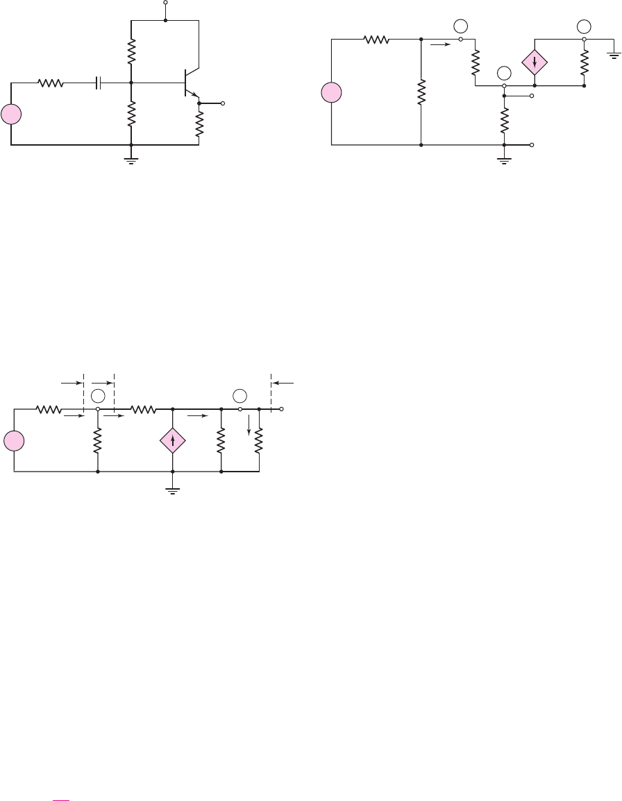
Initially, to find the output resistance of the emitter-follower circuit shown in
Figure 6.49, we will assume that the input signal source is ideal and that
R
S
= 0
. The
circuit shown in Figure 6.52 can be used to determine the output resistance looking
back into the output terminals. The circuit is derived from the small-signal equivalent
6.6.2
+
–
V
p
r
o
R
E
V
x
I
x
g
m
V
p
r
p
R
1
⎜⎜
R
2
+
–
R
o
Figure 6.52 Small-signal equivalent circuit of the emitter-follower used to determine the
output resistance. The source resistance R
S
is assumed to be zero (an ideal signal source).
nea80644_ch06_369-468.qxd 06/13/2009 07:32 PM Page 423 F506 Hard disk:Desktop Folder:Rakesh:MHDQ134-06:

424 Part 1 Semiconductor Devices and Basic Applications
circuit shown in Figure 6.51 by setting the independent voltage source V
s
equal to
zero, which means that V
s
acts as a short circuit. A test voltage V
x
is applied to the out-
put terminal and the resulting test current is I
x
. The output resistance, R
o
, is given by
R
o
=
V
x
I
x
(6.69)
In this case, the control voltage
V
π
is not zero, but is a function of the applied test
voltage. From Figure 6.52, we see that
V
π
=−V
x
. Summing currents at the output
node, we have
I
x
+ g
m
V
π
=
V
x
R
E
+
V
x
r
o
+
V
x
r
π
(6.70)
Since
V
π
=−V
x
, Equation (6.70) can be written as
I
x
V
x
=
1
R
o
= g
m
+
1
R
E
+
1
r
o
+
1
r
π
(6.71)
or the output resistance is given by
R
o
=
1
g
m
R
E
r
o
r
π
(6.72)
The output resistance may also be written in a slightly different form. Equa-
tion (6.71) can be written in the form
1
R
o
=
g
m
+
1
r
π
+
1
R
E
+
1
r
o
=
1 + β
r
π
+
1
R
E
+
1
r
o
(6.73)
or the output resistance can be written in the form
R
o
=
r
π
1 + β
R
E
r
o
(6.74)
Equation (6.74) says that the output resistance looking back into the output terminals is
the effective resistance in the emitter,
R
E
r
o
, in parallel with the resistance looking back
into the emitter. In turn, the resistance looking into the emitter is the total resistance in
the base circuit divided by (
1 + β
). This is an important result and is called the inverse
resistance reflection rule and is the inverse of the reflection rule looking to the base.
EXAMPLE 6.13
Objective: Calculate the input and output resistance of the emitter-follower circuit
shown in Figure 6.49. Assume
R
S
= 0
.
The small-signal parameters, as determined in Example 6.12, are
r
π
= 3.28 k
,
β = 100
, and
r
o
= 100 k.
Solution (Input Resistance): The input resistance looking into the base was deter-
mined in Example 6.12 as
R
ib
= r
π
+(1 +β)(r
o
R
E
) = 3.28 +(101)(1002) = 201 k
and the input resistance seen by the signal source R
i
is
R
i
= R
1
R
2
R
ib
= 5050201 = 22.2k
Comment: The input resistance of the emitter-follower looking into the base is
substantially larger than that of the simple common-emitter circuit because of the
nea80644_ch06_369-468.qxd 06/13/2009 07:32 PM Page 424 F506 Hard disk:Desktop Folder:Rakesh:MHDQ134-06:

Chapter 6 Basic BJT Amplifiers 425
(
1 + β
) factor. This is one advantage of the emitter-follower circuit. However, in this
case, the input resistance seen by the signal source is dominated by the bias resistors
R
1
and R
2
. To take advantage of the large input resistance of the emitter-follower
circuit, the bias resistors must be designed to be much larger.
Solution (Output Resistance): The output resistance is found from Equa-
tion (6.74) as
R
o
=
r
π
1 + β
R
E
r
o
=
3.28
101
2100
or
R
o
= 0.03252100 = 0.0320 k ⇒ 32.0
The output resistance is dominated by the first term that has (
1 + β
) in the
denominator.
Comment: The emitter-follower circuit is sometimes referred to as an impedance
transformer, since the input impedance is large and the output impedance is small. The
very low output resistance makes the emitter-follower act almost like an ideal voltage
source, so the output is not loaded down when used to drive another load. Because of
this, the emitter-follower is often used as the output stage of a multistage amplifier.
EXERCISE PROBLEM
Ex 6.13: Consider the circuit and transistor parameters described in Exercise
Ex 6.12 for the circuit shown in Figure 6.49. For the case of
R
S
= 0
, determine the
output resistance looking into the output terminals. (Ans.
R
o
= 0.129 )
We can determine the output resistance of the emitter-follower circuit taking into
account a nonzero source resistance. The circuit in Figure 6.53 is derived from the
small-signal equivalent circuit shown in Figure 6.51 and can be used to find R
o
. The
independent source
V
s
is set equal to zero and a test voltage V
x
is applied to the output
terminals. Again, the control voltage
V
π
is not zero, but is a function of the test
voltage. Summing currents at the output node, we have
I
x
+ g
m
V
π
=
V
x
R
E
+
V
x
r
o
+
V
x
r
π
+ R
1
R
2
R
S
(6.75)
The control voltage can be written in terms of the test voltage by a voltage divider
equation as
V
π
=−
r
π
r
π
+ R
1
R
2
R
S
· V
x
(6.76)
+
–
V
p
r
o
R
E
R
S
V
x
I
x
g
m
V
p
r
p
R
1
⎜⎜
R
2
+
–
R
o
E
Figure 6.53 Small-signal equivalent circuit of the emitter-follower used to determine the
output resistance including the effect of the source resistance R
S
nea80644_ch06_369-468.qxd 06/13/2009 07:32 PM Page 425 F506 Hard disk:Desktop Folder:Rakesh:MHDQ134-06:

426 Part 1 Semiconductor Devices and Basic Applications
Equation (6.75) can then be written as
I
x
=
g
m
r
π
r
π
+ R
1
R
2
R
S
· V
x
+
V
x
R
E
+
V
x
r
o
+
V
x
r
π
+ R
1
R
2
R
S
(6.77)
Noting that
g
m
r
π
= β
, we find
I
x
V
x
=
1
R
o
=
1 + β
r
π
+ R
1
R
2
R
S
+
1
R
E
+
1
r
o
(6.78)
or
R
o
=
r
π
+ R
1
R
2
R
S
1 + β
R
E
r
o
(6.79)
In this case, the source resistance and bias resistances contribute to the output
resistance.
Small-Signal Current Gain
We can determine the small-signal current gain of an emitter-follower by using the input
resistance and the concept of current dividers. For the small-signal emitter-follower
equivalent circuit shown in Figure 6.51, the small signal current gain is defined as
A
i
=
I
e
I
i
(6.80)
where I
e
and I
i
are the output and input current phasors.
Using a current divider equation, we can write the base current in terms of the
input current, as follows:
I
b
=
R
1
R
2
R
1
R
2
+ R
ib
I
i
(6.81)
Since
g
m
V
π
= β I
b
, then,
I
o
= (1 +β)I
b
= (1 +β)
R
1
R
2
R
1
R
2
+ R
ib
I
i
(6.82)
Writing the load current in terms of I
o
produces
I
e
=
r
o
r
o
+ R
E
I
o
(6.83)
Combining Equations (6.82) and (6.83), we obtain the small-signal current gain, as
follows:
A
i
=
I
e
I
i
= (1 +β)
R
1
R
2
R
1
R
2
+ R
ib
r
o
r
o
+ R
E
(6.84)
If we assume that
R
1
R
2
R
ib
and
r
o
R
E
, then
A
i
∼
=
(1 + β)
(6.85)
which is the current gain of the transistor.
Although the small-signal voltage gain of the emitter follower is slightly less
than 1, the small-signal current gain is normally greater than 1. Therefore, the emitter-
follower circuit produces a small-signal power gain.
6.6.3
nea80644_ch06_369-468.qxd 06/13/2009 07:32 PM Page 426 F506 Hard disk:Desktop Folder:Rakesh:MHDQ134-06:

Chapter 6 Basic BJT Amplifiers 427
Although we did not explicitly calculate a current gain in the common-emitter
circuit previously, the analysis is the same as that for the emitter-follower and in gen-
eral the current gain is also greater than unity.
DESIGN EXAMPLE 6.14
Objective: To design an emitter-follower amplifier to meet an output resistance
specification.
Specifications: Consider the output signal of the amplifier designed in Example 6.7. We
now want to design an emitter-follower circuit with the configuration shown in Figure
6.54 such that the output signal from this circuit does not vary by more than 5 percent
when a load in the range
R
L
= 4k
to
R
L
= 20 k
is connected to the output.
Choices: We will assume that a transistor with nominal parameter values of
β = 100
,
V
BE
(on) = 0.7
V, and
V
A
= 80
V is available.
Discussion: The output resistance of the common-emitter circuit designed in Example
6.7 is
R
o
= R
C
= 10 k
. Connecting a load resistance between
4k
and
20 k
will
load down this circuit, so that the output voltage will change substantially. For this rea-
son, an emitter-follower circuit with a low output resistance must be designed to mini-
mize the loading effect. The Thevenin equivalent circuit is shown in Figure 6.55. The
output voltage can be written as
v
o
=
R
L
R
L
+ R
o
· v
TH
where
v
TH
is the ideal voltage generated by the amplifier. In order to have
v
o
change
by less than 5 percent as a load resistance R
L
is added, we must have R
o
less than or
equal to approximately 5 percent of the minimum value of R
L
. In this case, then, we
need R
o
to be approximately 200
.
Initial Design Approach: Consider the emitter-follower circuit shown in Figure 6.54.
Note that the source resistance is
R
S
= 10 k
, corresponding to the output resistance
of the circuit designed in Example 6.7.
+
–
v
o
v
s
R
S
= 10 kΩ
V
+
= +5 V
V
–
= –5 V
C
C1
C
C2
R
E
R
L
R
1
R
2
Figure 6.54 Figure for Example 6.14
+
–
+
v
TH
v
o
R
o
R
L
–
Figure 6.55 Thevenin equivalent
of the output of an amplifier
nea80644_ch06_369-468.qxd 06/13/2009 07:32 PM Page 427 F506 Hard disk:Desktop Folder:Rakesh:MHDQ134-06: