Neamen D. Microelectronics: Circuit Analysis and Design
Подождите немного. Документ загружается.

448 Part 1 Semiconductor Devices and Basic Applications
We include emitter resistors to help stabilize the voltage gain of the amplifier.
Assume that each transistor has a current gain of
β = 100
.
The overall gain (magnitude) of this amplifier must be
v
o3
v
o1
=
1.28
0.00892
= 144
We will design the amplifier so that the individual gains (magnitudes) are
A
v3
=
v
o3
v
o2
= 5 and
|
A
v2
|
=
v
o2
v
o1
= 28.8
The dc voltage at the collector of Q
3
(with
V
BE4
(on) = 0.7V
) is
V
C3
= V
B4
=
6 + 0.7 = 6.7V
. The quiescent base current to the output transistor is
I
B4
=
0.294/50
or
I
B4
= 5.88
mA. If we set the quiescent collector current in Q
3
to be
I
CQ3
= 15
mA, then
I
RC3
= 15 +5.88 = 20.88
mA. Then
R
C3
=
V
CC
− V
C3
I
RC3
=
12 − 6.7
20.88
⇒ 254
Also
r
π3
=
β
3
V
T
I
CQ3
=
(100)(0.026)
15
⇒ 173
We also find
R
i4
= r
π4
+(1 +β
4
)(R
E4
R
L
)
= 4.42 +(51)(208) = 296
The small-signal voltage gain, for a common-emitter amplifier with an emitter resis-
tor, can be written as
A
v3
=|
v
o3
v
o2
|=
β
3
(R
C3
R
i4
)
r
π3
+(1 +β
3
)R
E3
Setting
A
v3
= 5
, we have
5 =
(100)(254296)
173 + (101)R
E3
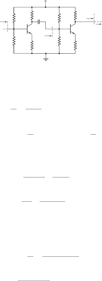
R
3
R
4
R
C2
V
C3
=
V
B4
v
o2
R
i3
V
CC
= 12 V
R
E3
R
i4
R
C3
R
6
R
5
R
E2
Q
2
v
o1
Q
3
R
i2
I
B4
v
o3
Figure 6.79 Gain stage (two-stage common-emitter amplifier) for design application
nea80644_ch06_369-468.qxd 06/13/2009 07:32 PM Page 448 F506 Hard disk:Desktop Folder:Rakesh:MHDQ134-06:

Chapter 6 Basic BJT Amplifiers 449
which yields
R
E3
= 25.4
.
If we set
R
5
R
6
= 50 k
, we find
R
5
= 69.9k
and
R
6
= 176 k
.
Finally, if we set
V
C2
= 6V
and
I
CQ2
= 5mA
, then
R
C2
=
V
CC
− V
C2
I
CQ2
=
12 − 6
5
= 1.2k
Also
r
π2
=
β
2
V
T
I
CQ2
=
(100)(0.026)
5
= 0.52 k
and
R
i3
= R
5
R
6
[
r
π3
+(1 +β
3
)R
E3
]
= 50[0.173 +(101)(0.0254)] = 2.60 k
The expression for the voltage gain can be written as
|A
v2
|=
v
o2
v
o1
=
β
2
(R
C2
R
i3
)
r
π2
+(1 +β
2
)R
E2
Setting
|A
v2
|=28.8
, we find
28.8 =
(100)(1.22.6)
0.52 + (101)R
E2
which yields
R
E2
= 23.1
.
If we set
R
3
R
4
= 50 k
, we find
R
3
= 181 k
and
R
4
= 69.1k
.
Comment: We may note that, as with any design, there is no unique solution. In ad-
dition, to actually build this circuit with discrete components, we would need to use
standard values for resistors, which means the quiescent current and voltage values
will change, and the overall voltage gain will probably change from the designed
value. Also, the current gains of the actual transistors used will probably not be
exactly equal to the assumed values. Therefore some slight modifications will likely
need to be made in the final design.
Discussion: We implicitly assumed that we were designing an audio amplifier, but
we have not discussed the frequency response. For example, the coupling capacitors
in the design must be large enough to pass audio signal frequencies. The frequency
response of amplifiers will be discussed in detail in Chapter 7.
We will also see in later chapters, in particular Chapter 8, that a more efficient
output stage can be designed. The efficiency of the output stage in this design is rel-
atively small; that is, the average signal power delivered to the load is small com-
pared to the average power dissipated in the output stage. However, this design is a
first approximation in the design process.
6.12 SUMMARY
• This chapter emphasized the application of bipolar transistors in linear amplifier
circuits. The basic process by which a transistor circuit can amplify a small time-
varying signal was discussed.
nea80644_ch06_369-468.qxd 06/13/2009 07:32 PM Page 449 F506 Hard disk:Desktop Folder:Rakesh:MHDQ134-06:

450 Part 1 Semiconductor Devices and Basic Applications
• The hybrid-
π
small-signal equivalent circuit of the bipolar transistor was devel-
oped. This equivalent circuit is used in the analysis and design of transistor lin-
ear amplifiers.
•
Three basic circuit configurations were considered: the common-emitter, emitter-
follower, and common-base. These three configurations form the basic building
blocks for more complex integrated circuits.
• The common-emitter circuit amplifies both time-varying voltages and currents.
• The emitter-follower circuit amplifies time-varying currents, and has a large
input resistance and low output resistance.
• The common-base circuit amplifies time-varying voltages, and has a low input
resistance and large output resistance.
• Three multitransistor circuits were considered: a cascade configuration of two
common-emitter circuits, a Darlington pair, and a cascode configuration formed
by common-emitter and common-base circuits. Each configuration provides
specialized characteristics such as overall larger voltage gain or an overall larger
current gain.
• The concept of signal power gain in amplifier circuits was discussed. There is a
redistribution of power within the amplifier circuit.
• As an application, bipolar transistors were incorporated in the design of a multi-
stage amplifier circuit configuration to provide a specified output signal power.
CHECKPOINT
After studying this chapter, the reader should have the ability to:
✓ Explain graphically the amplification process in a simple bipolar amplifier circuit.
✓ Describe the small-signal hybrid-
π
equivalent circuit of the bipolar transistor
and to determine the values of the small-signal hybrid-
π
parameters.
✓ Apply the small-signal hybrid-
π
equivalent circuit to various bipolar amplifier
circuits to obtain the time-varying circuit characteristics.
✓ Characterize the small-signal voltage and current gains and the input and output
resistances of the common-emitter, emitter-follower, and common-base
amplifiers.
✓ Determine the maximum symmetrical swing in the output signal of an amplifier.
✓ Apply the bipolar small-signal equivalent circuit in the analysis of multistage
amplifier circuits.
REVIEW QUESTIONS
1. Discuss, using the concept of a load line, how a simple common-emitter circuit
can amplify a time-varying signal.
2. Why can the analysis of a transistor circuit be split into a dc analysis, with all ac
sources set equal to zero, and an ac analysis, with all dc sources set equal to
zero?
3. What does the term small-signal imply?
4. Sketch the hybrid-
π
equivalent circuit of an npn and a pnp bipolar transistor.
5. State the relationships of the small-signal hybrid-
π
parameters
g
m
,
r
π
,and r
o
to
the transistor dc quiescent values.
6. What are the physical meanings of the hybrid-
π
parameters
r
π
and r
o
?
7. Sketch a simple common-emitter amplifier circuit and discuss the general ac
circuit characteristics (voltage gain, current gain, input and output resistances).
nea80644_ch06_369-468.qxd 06/13/2009 07:32 PM Page 450 F506 Hard disk:Desktop Folder:Rakesh:MHDQ134-06:

Chapter 6 Basic BJT Amplifiers 451
8. What are the changes in the dc and ac characteristics of a common-emitter am-
plifier when an emitter resistor and an emitter bypass capacitor are incorporated
in the design?
9. Discuss the concepts of a dc load line and an ac load line.
10. Sketch a simple emitter-follower amplifier circuit and discuss the general ac
circuit characteristics (voltage gain, current gain, input and output resistances).
11. Sketch a simple common-base amplifier circuit and discuss the general ac circuit
characteristics (voltage gain, current gain, input and output resistances).
12. Compare the ac circuit characteristics of the common-emitter, emitter-follower,
and common-base circuits.
13. Discuss the general conditions under which a common-emitter amplifier, an
emitter-follower amplifier, and a common-base amplifier would be used in an
electronic circuit design.
14. State at least two reasons why a multistage amplifier circuit would be required in
a design rather than a single-stage circuit.
PROBLEMS
[Note: In the following problems, assume that the B–E turn-on voltage is 0.7 V for
both npn and pnp transistors and that
V
A
=∞
unless otherwise stated. Also assume
that all capacitors act as short circuits to the signal.]
Section 6.2 The Bipolar Linear Amplifier
6.1 (a) Determine the small-signal parameters
g
m
,
r
π
, and
r
o
of a transistor with
parameters
β = 180
and
V
A
= 150
V for bias currents of (i)
I
CQ
= 0.5
mA
and (ii)
I
CQ
= 2
mA. (b) Repeat part (a) for
β = 80
and
V
A
= 100
V when
biased at (i)
I
CQ
= 0.25
mA and (ii)
I
CQ
= 80 μ
A.
6.2 (a) The transistor parameters are
β = 125
and
V
A
= 200
V. A value of
g
m
= 95
mA/V is desired. Determine the required collector current and then
find
r
π
and
r
o
. (b) A second transistor has small-signal parameters of
g
m
= 120
mA/V and
r
π
= 1.2
k
. What is the quiescent collector current
and the transistor current gain?
6.3 A transistor has a current gain in the range
90 ≤ β ≤ 180
and the quiescent
collector current is in the range
0.8 ≤ I
CQ
≤ 1.2
mA. What is the possible
range in the small-signal parameters
g
m
and
r
π
?
6.4 The transistor in Figure 6.3 has parameters
β = 120
and
V
A
=∞
. The cir-
cuit parameters are
V
CC
= 3.3
V,
R
C
= 15
k
, and
I
CQ
= 0.12
mA.
A small signal
v
be
= 5 sin ωt
mV is applied. (a) Determine
i
C
and
υ
CE
.
(b) What is the small-signal voltage gain
A
v
= v
ce
/v
be
?
6.5 For the circuit in Figure 6.3, the transistor parameters are
β = 120
,
V
BE
(on) = 0.7
V, and
V
A
= 80
V. The circuit parameters are
V
CC
= 3.3
V,
V
BB
= 1.10
V,
R
C
= 4
k
, and
R
B
= 110
k
. (a) Determine the hybrid-
π
parameters. (b) Find the small-signal voltage gain
A
v
= v
o
/v
s
. (c) If the
time-varying output signal is given by
v
o
= 0.5 sin(100t)
V, what is
v
s
(t)
?
6.6 For the circuit in Figure 6.3,
β = 120
,
V
CC
= 5
V,
V
A
= 100
V, and
R
B
= 25 k
. (a) Determine
V
BB
and
R
C
such that
r
π
= 5.4k
and the Q-
point is in the center of the load line. (b) Find the resulting small-signal
voltage gain
A
v
= v
o
/v
s
.
nea80644_ch06_369-468.qxd 06/13/2009 07:32 PM Page 451 F506 Hard disk:Desktop Folder:Rakesh:MHDQ134-06:
452 Part 1 Semiconductor Devices and Basic Applications
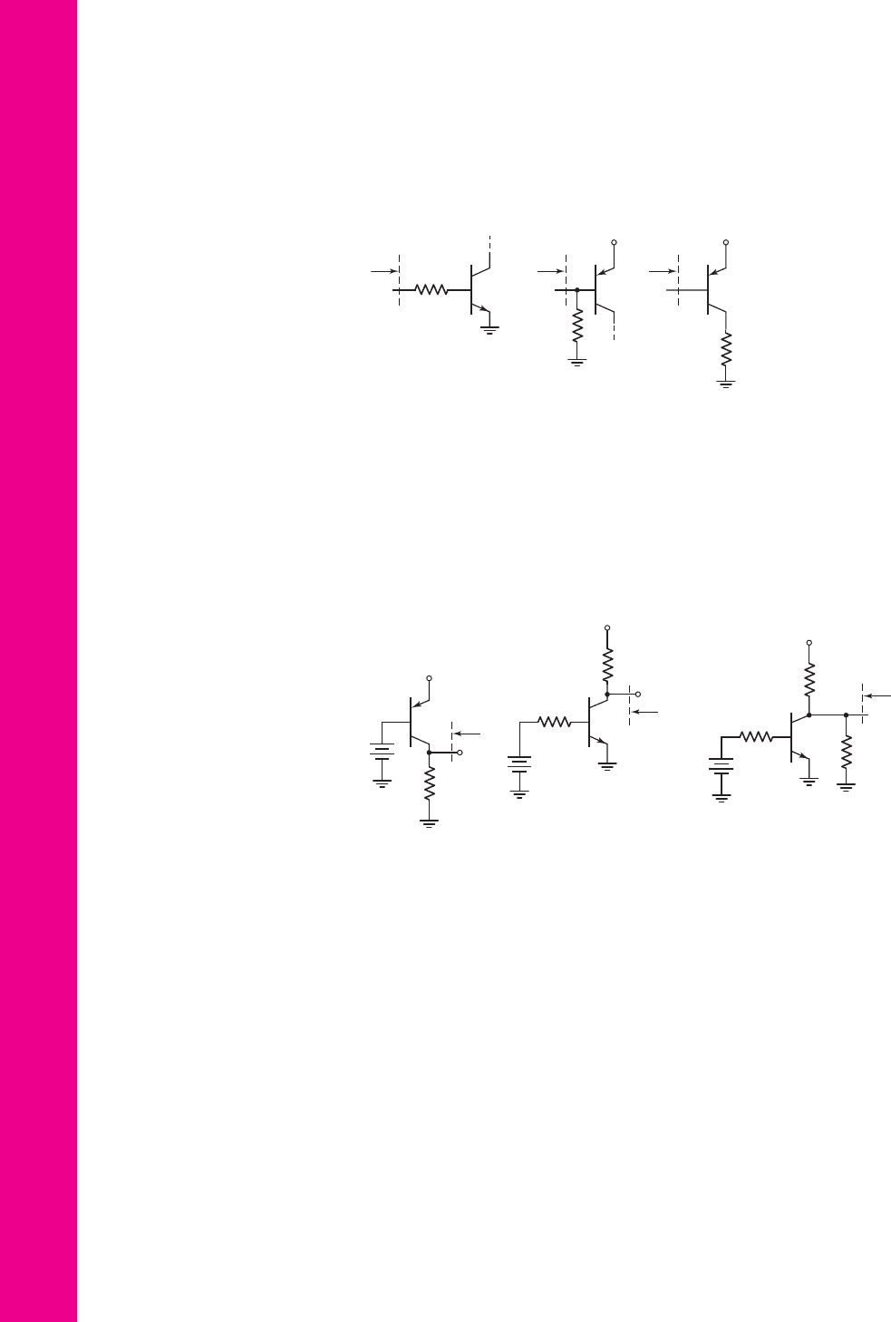
6.7 The parameters of each transistor in the circuits shown in Figure P6.7 are
β = 120
and
I
CQ
= 0.5
mA. Determine the input resistance
R
i
for each
circuit.
6.9 The circuit in Figure 6.3 is biased at
V
CC
= 10
V and has a collector resis-
tor of
R
C
= 4k
. The voltage
V
BB
is adjusted such that
V
C
= 4
V. The
transistor has
β = 100
. The signal voltage between the base and emitter is
v
be
= 5
sin
ω
t(mV). Determine the total instantaneous values of
i
B
(t)
,
i
C
(t)
, and
v
C
(t)
, and determine the small-signal voltage gain
A
v
=
v
c
(t)/v
be
(t)
.
6.10 For the circuit in Figure 6.14,
β = 100
,
V
A
=∞
,
V
CC
=
10 V, and
R
B
= 50 k
. (a) Determine
V
BB
and
R
C
such that
I
CQ
= 0.5
mA and the
Q-point is in the center of the load line. (b) Find the small-signal parameters
g
m
,
r
π
, and
r
o
. (c) Determine the small-signal voltage gain
A
v
= v
o
/v
s
.
6.11 The ac equivalent circuit shown in Figure 6.7 has
R
C
= 2k
. The transis-
tor parameters are
g
m
= 50
mA/V and
β = 100
. The time-varying output
voltage is given by
v
o
= 1.2
sin
ωt
(V). Determine
v
be
(t)
and
i
b
(t)
.
R
B
= 50 kΩ
R
i
R
i
R
B
=
100 kΩ
R
C
=
4 kΩ
V
+
R
i
V
+
(a) (b) (c)
Figure P6.7
6.8 The parameters of each transistor in the circuits shown in Figure P6.8 are
β = 130
,
V
A
= 80
V, and
I
CQ
= 0.2
mA. Determine the output resistance
R
o
for each circuit.
(a) (b) (c)
R
C
=
4 kΩ
R
C
= 10 kΩ
V
+
R
o
R
o
+
–
V
BB
+
–
V
BB
+
–
V
BB
R
o
R
B
= 100 kΩ
R
B
= 50 kΩ
V
+
R
C
=
10 kΩ
V
+
R
L
= 5 kΩ
Figure P6.8
nea80644_ch06_369-468.qxd 06/13/2009 07:32 PM Page 452 F506 Hard disk:Desktop Folder:Rakesh:MHDQ134-06:

Chapter 6 Basic BJT Amplifiers 453
Section 6.4 Common-Emitter Amplifier
6.12 The parameters of the transistor in the circuit in Figure P6.12 are
β = 150
and
V
A
=∞
. (a) Determine R
1
and R
2
to obtain a bias-stable circuit with
the Q-point in the center of the load line. (b) Determine the small-signal
voltage gain
A
v
= v
o
/v
s
.
v
O
v
s
R
C
= 1.2 kΩ
V
+
= +5 V
V
–
= –5 V
R
2
R
1
C
C
R
E
= 0.2 kΩ
+
–
Figure P6.12
6.13 Assume that
β = 100
,
V
A
=∞
,
R
1
= 33
k
, and
R
2
= 50
k
for the
circuit in Figure P6.13. (a) Plot the
Q
-point on the dc load line. (b) Deter-
mine the small-signal voltage gain. (c) Determine the range in voltage gain
if
R
1
and
R
2
vary by
±5
percent.
D6.14 The transistor parameters for the circuit in Figure P6.13 are
β = 100
and
V
A
=∞
. (a) Design the circuit such that it is bias stable and that the
Q-point is in the center of the load line. (b) Determine the small-signal
voltage gain of the designed circuit.
v
O
v
s
R
E
= 1 kΩ
V
CC
= 3.3 V
R
2
R
1
C
C
R
C
= 2 kΩ
+
–
Figure P6.13
D6.15 For the circuit in Figure P6.15, the transistor parameters are
β = 100
and
V
A
=∞
. Design the circuit such that
I
CQ
= 0.25
mA and
V
CEQ
= 3
V.
R
C
C
E
C
C
v
s
v
O
R
B
=
50 kΩ
V
–
= –5 V
V
+
= +5 V
R
S
= 100 Ω
R
E
+
–
Figure P6.15
nea80644_ch06_369-468.qxd 06/13/2009 07:32 PM Page 453 F506 Hard disk:Desktop Folder:Rakesh:MHDQ134-06:

454 Part 1 Semiconductor Devices and Basic Applications
D6.17 (a) For transistor parameters
β = 80
and
V
A
= 100
V, (i) design the circuit
in Figure P6.17 such that the dc voltages at the base and collector terminals
are 0.20 V and
−3
V, respectively, and (ii) determine the small-signal
transconductance function
G
f
= i
o
/v
s
. (b) Repeat part (a) for
β = 120
and
V
A
= 80
V.
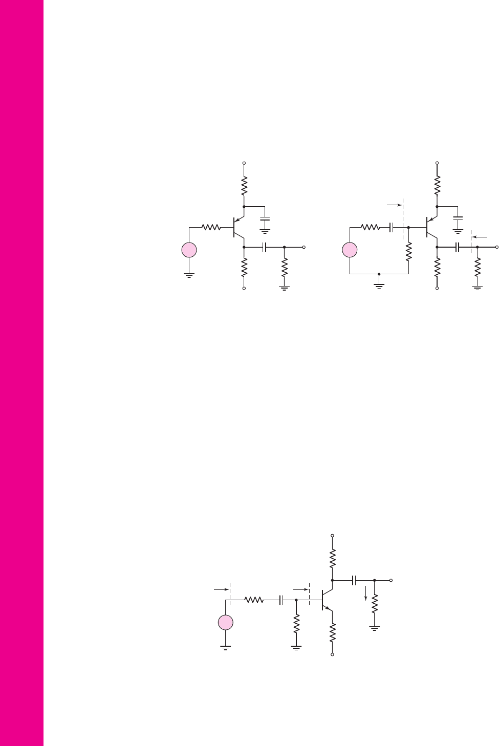
6.18 The signal source in Figure P6.18 is
v
s
= 5 sin ωt
mV. The transistor para-
meters are
β = 120
and
V
A
=∞
. (a) (i) Design the circuit such that
I
CQ
= 0.25
mA and
V
CEQ
= 3
V. (ii) Find the small-signal voltage gain
A
v
= v
o
/v
s
. (iii) Find
v
o
(t)
. (b) Repeat part (a) for
R
S
= 0
.
v
o
i
s
R
L
= 1 kΩ
R
C
=
2.2 kΩ
V
CC
= +9 V
R
E
=
2 kΩ
R
2
R
1
C
E
C
C2
C
C1
Figure P6.16
I
Eo
= 0.80 mA
C
C2
C
E
v
s
V
–
= –5 V
V
+
= +5 V
R
C
R
B
R
L
= 4 kΩ
v
o
C
C1
i
o
+
–
Figure P6.17
C
C
C
E
v
s
V
–
= –5 V
V
+
= +5 V
R
E
R
C
R
L
= 5 kΩ
R
S
= 2.5 kΩ
v
o
+
–
Figure P6.18
Find the small-signal voltage gain
A
v
= v
o
/v
s
. Find the input resistance
seen by the signal source
v
s
.
D6.16 Assume the transistor in the circuit in Figure P6.16 has parameters
β = 120
and
V
A
= 100
V. (a) Design a bias-stable circuit such that
V
CEQ
= 5.20
V.
(b) Determine the small-signal transresistance function
R
m
= v
o
/i
s
.
(c) Using the results of part (a), determine the variation in
R
m
if
100 ≤ β ≤ 150
.
nea80644_ch06_369-468.qxd 06/13/2009 07:32 PM Page 454 F506 Hard disk:Desktop Folder:Rakesh:MHDQ134-06:

Chapter 6 Basic BJT Amplifiers 455
6.19 Consider the circuit shown in Figure P6.19 where the signal-source is
v
s
= 4 sin ωt
mV. (a) For transistor parameters of
β = 80
and
V
A
=∞
,
(i) find the small-signal voltage gain
A
v
= v
o
/v
s
and the transconductance
function
G
f
= i
o
/v
s
, and (ii) calculate
v
o
(t)
and
i
o
(t)
. (b) Repeat part (a)
for
β = 120
.
C
E
C
C
v
o
v
s
V
–
= –5 V
V
+
= +5 V
R
E
= 10 kΩ
R
L
=
5 kΩ
R
C
=
5 kΩ
R
S
= 2.5 kΩ
+
–
i
s
i
o
Figure P6.19
C
C2
C
E
v
s
V
CC
= 9 V
R
L
=
2 kΩ
R
C
=
2.2 kΩ
R
E
=
1.2 kΩ
R
S
=
10 kΩ
R
1
=
27 kΩ
R
2
=
15 kΩ
C
C1
v
o
+
–
i
s
R
i
i
o
Figure P6.20
6.20 Consider the circuit shown in Figure P6.20. The transistor parameters are
β = 100
and
V
A
= 100
V. Determine R
i
,
A
v
= v
o
/v
s
, and
A
i
= i
o
/i
s
.
6.21 The parameters of the transistor in the circuit in Figure P6.21 are
β = 100
and
V
A
= 100
V. (a) Find the dc voltages at the base and emitter terminals.
(b) Find R
C
such that
V
CEQ
= 3.5
V. (c) Assuming C
C
and C
E
act as short
circuits, determine the small-signal voltage gain
A
v
= v
o
/v
s
. (d) Repeat
part (c) if a
500
source resistor is in series with the
v
s
signal source.
+
–
R
C
C
E
C
C
v
s
v
O
R
B
=
10 kΩ
R
S
= 100 Ω
I =
0.35 mA
V
–
= –5 V
V
+
= +5 V
+
–
Figure P6.21
v
o
v
s
R
L
= 1.2 kΩ
R
S
= 200 Ω
R
C
=
1 kΩ
V
+
= +5 V
R
E
=
0.1 kΩ
R
2
=
1.5 kΩ
R
1
= 6 kΩ
C
E
C
C2
C
C1
+
–
Figure P6.22
6.22 For the circuit in Figure P6.22, the transistor parameters are
β = 180
and
r
o
=∞
. (a) Determine the Q-point values. (b) Find the small-signal
hybrid-
π
parameters. (c) Find the small-signal voltage gain
A
v
= v
o
/v
s
.
nea80644_ch06_369-468.qxd 06/13/2009 07:32 PM Page 455 F506 Hard disk:Desktop Folder:Rakesh:MHDQ134-06:
456 Part 1 Semiconductor Devices and Basic Applications
6.23 For the circuit in Figure P6.23, the transistor parameters are
β = 80
and
V
A
= 80
V. (a) Determine R
E
such that
I
EQ
= 0.75
mA. (b) Determine R
C
such that
V
ECQ
= 7
V. (c) For
R
L
= 10 k
, determine the small-signal
voltage gain
A
v
= v
o
/v
s
. (d) Determine the impedance seen by the signal
source
v
s
.
6.24 The transistor in the circuit in Figure P6.24 has parameters
V
EB
(on) = 0.7
V,
V
A
= 50
V, and a current gain in the range
80 ≤ β ≤ 120
. Determine (a) the
range in the small-signal voltage gain
A
v
= v
o
/v
s
, (b) the range in the input
resistance
R
i
, and (c) the range in the output resistance
R
o
.
D6.25 Design a one-transistor common-emitter preamplifier that can amplify a
10 mV (rms) microphone signal and produce a 0.5 V (rms) output signal.
The source resistance of the microphone is 1 k
. Use standard resistor
values in the design and specify the value of
β
required.
6.26 For the transistor in the circuit in Figure P6.26, the parameters are
β = 100
and
V
A
=∞
. (a) Determine the Q-point. (b) Find the small-signal parame-
ters
g
m
,
r
π
, and
r
o
. (c) Find the small-signal voltage gain
A
v
= v
o
/v
s
and
the small-signal current gain
A
i
= i
o
/i
s
. (d) Find the input resistances
R
ib
and
R
is
. (e) Repeat part (c) if
R
S
= 0
.
R
E
R
S
= 2 kΩ
C
C
C
E
v
s
V
–
= – 9 V
V
+
= +9 V
R
C
R
L
v
o
+
–
Figure P6.23
C
C2
C
E
v
s
V
–
= –6 V
V
+
= +4 V
R
B
= 5 kΩ
R
C
=
4 kΩ
R
S
= 1 kΩ
R
E
= 5 kΩ
R
L
= 4 kΩ
v
o
C
C1
R
i
R
o
+
–
Figure P6.24
R
C
= 6.8 kΩ
C
C1
C
C2
v
s
v
o
R
B
=
10 kΩ
R
S
= 0.5 kΩ
V
+
= +16 V
V
–
= –6 V
R
E
=
3 kΩ
R
L
=
6.8 kΩ
R
is
R
ib
i
o
+
–
Figure P6.26
nea80644_ch06_369-468.qxd 06/13/2009 07:32 PM Page 456 F506 Hard disk:Desktop Folder:Rakesh:MHDQ134-06:

Chapter 6 Basic BJT Amplifiers 457
6.27 If the collector of a transistor is connected to the base terminal, the transis-
tor continues to operate in the forward-active mode, since the B–C junction
is not reverse biased. Determine the small-signal resistance,
r
e
= v
ce
/i
e
,of
this two-terminal device in terms of g
m
,
r
π
, and
r
o
.
D6.28 (a) Design an amplifier with the configuration similar to that shown in
Figure 6.31. The circuit is to be biased with
V
CC
= 3.3
V and the source re-
sistance is
R
S
= 100
. The minimum small-signal voltage gain is to be
|
A
v
|
= 10
. The available npn transistors have parameters of
β = 120
and
V
A
=∞
. (b) Using the results of part (a), what is the resulting input resis-
tance seen by the signal source and what is the resulting output resistance?
D6.29 An ideal signal voltage source is given by
v
s
= 5 sin(5000t)
(mV). The
peak current that can be supplied by this source is
0.2 μA
. The desired out-
put voltage across a
10 k
load resistor is
v
o
= 100 sin(5000t)
(mV). De-
sign a one-transistor common-emitter amplifier to meet this specification.
Use standard resistor values and specify the required value of
β
.
D6.30 Design a one-transistor common-emitter amplifier with a small-signal volt-
age gain of approximately
A
v
=−10
. The circuit is to be biased from a
single power supply of
V
CC
= 5
V that can supply a maximum current of
0.8 mA. The input resistance is to be greater than 20 k
and the output
resistance is to be 5 k
. The available transistor is a pnp device with
β = 90
and
V
A
=∞
.
D6.31 Design a common-emitter circuit whose output is capacitively coupled to a
load resistor
R
L
= 10 k
. The minimum small-signal voltage gain is to be
|A
v
|=50
. The circuit is to be biased at
±5
V and each voltage source can
supply a maximum of 0.5 mA. The parameters of the available transistors
are
β = 120
and
V
A
=∞
.
Section 6.5 AC Load Line Analysis
6.32 Consider the circuit shown in Figure P6.13. Assume
R
1
= 33
k
and
R
2
= 50
k
. The transistor parameters are
β = 100
and
V
A
=∞
. Deter-
mine the maximum undistorted swing in the output voltage if the total in-
stantaneous E–C voltage is to remain in the range
0.5 ≤ v
EC
≤ 3
V.
6.33 For the circuit in Figure P6.15, let
β = 100
,
V
A
=∞
,
R
E
= 12.9k
, and
R
C
= 6k
. Determine the maximum undistorted swing in the output
voltage if the total instantaneous C–E voltage is to remain in the range
1 ≤ v
CE
≤ 9
V and if the total instantaneous collector current is to remain
greater or equal to
50 μA
.
6.34 Consider the circuit in Figure P6.19. The transistor parameters are
β = 80
and
V
A
=∞
. (a) Determine the maximum undistorted swing in the output
voltage if the total instantaneous C–E voltage is to remain in the range
0.7 ≤ v
CE
≤ 9
V and the instantaneous collector is to be
i
C
≥ 0
. (b) Using
the results of part (a), determine the range in collector current.
6.35 The parameters of the circuit shown in Figure P6.17 are
R
B
= 20
k
and
R
C
= 2.5
k
. The transistor parameters are
β = 80
and
V
A
=∞
. Deter-
mine the maximum undistorted swing in the output current
i
o
if the total in-
stantaneous collector current is to be
i
C
≥ 0.08
mA and the total instanta-
neous E–C voltage is to be in the range
1 ≤ v
EC
≤ 9
V.
6.36 Consider the circuit in Figure P6.26 with transistor parameters described in
Problem 6.26. Determine the maximum undistorted swing in the output
nea80644_ch06_369-468.qxd 06/13/2009 07:32 PM Page 457 F506 Hard disk:Desktop Folder:Rakesh:MHDQ134-06: